EP1139079A2 - Messverfahren zur Bestimmung der optischen Transmission oder Reflexion - Google Patents
Messverfahren zur Bestimmung der optischen Transmission oder Reflexion Download PDFInfo
- Publication number
- EP1139079A2 EP1139079A2 EP01890086A EP01890086A EP1139079A2 EP 1139079 A2 EP1139079 A2 EP 1139079A2 EP 01890086 A EP01890086 A EP 01890086A EP 01890086 A EP01890086 A EP 01890086A EP 1139079 A2 EP1139079 A2 EP 1139079A2
- Authority
- EP
- European Patent Office
- Prior art keywords
- modulation
- luminosity
- frequency
- rectification
- modulated
- Prior art date
- Legal status (The legal status is an assumption and is not a legal conclusion. Google has not performed a legal analysis and makes no representation as to the accuracy of the status listed.)
- Withdrawn
Links
Images

Classifications
-
- G—PHYSICS
- G01—MEASURING; TESTING
- G01J—MEASUREMENT OF INTENSITY, VELOCITY, SPECTRAL CONTENT, POLARISATION, PHASE OR PULSE CHARACTERISTICS OF INFRARED, VISIBLE OR ULTRAVIOLET LIGHT; COLORIMETRY; RADIATION PYROMETRY
- G01J1/00—Photometry, e.g. photographic exposure meter
- G01J1/02—Details
- G01J1/08—Arrangements of light sources specially adapted for photometry standard sources, also using luminescent or radioactive material
-
- G—PHYSICS
- G01—MEASURING; TESTING
- G01J—MEASUREMENT OF INTENSITY, VELOCITY, SPECTRAL CONTENT, POLARISATION, PHASE OR PULSE CHARACTERISTICS OF INFRARED, VISIBLE OR ULTRAVIOLET LIGHT; COLORIMETRY; RADIATION PYROMETRY
- G01J3/00—Spectrometry; Spectrophotometry; Monochromators; Measuring colours
- G01J3/02—Details
- G01J3/06—Scanning arrangements arrangements for order-selection
-
- G—PHYSICS
- G01—MEASURING; TESTING
- G01J—MEASUREMENT OF INTENSITY, VELOCITY, SPECTRAL CONTENT, POLARISATION, PHASE OR PULSE CHARACTERISTICS OF INFRARED, VISIBLE OR ULTRAVIOLET LIGHT; COLORIMETRY; RADIATION PYROMETRY
- G01J3/00—Spectrometry; Spectrophotometry; Monochromators; Measuring colours
- G01J3/02—Details
- G01J3/10—Arrangements of light sources specially adapted for spectrometry or colorimetry
-
- G—PHYSICS
- G01—MEASURING; TESTING
- G01N—INVESTIGATING OR ANALYSING MATERIALS BY DETERMINING THEIR CHEMICAL OR PHYSICAL PROPERTIES
- G01N21/00—Investigating or analysing materials by the use of optical means, i.e. using sub-millimetre waves, infrared, visible or ultraviolet light
- G01N21/17—Systems in which incident light is modified in accordance with the properties of the material investigated
- G01N21/25—Colour; Spectral properties, i.e. comparison of effect of material on the light at two or more different wavelengths or wavelength bands
- G01N21/255—Details, e.g. use of specially adapted sources, lighting or optical systems
Definitions
- the invention relates to a measuring method for determining the optical transmission or reflection as well as measurement variables derived therefrom, the measurement radiation starting from a modulated radiation source after the interaction with a measurement object detected by a detector, into an electrical one Signal converted, frequency-selective amplification and an evaluation device is fed.
- Such methods and the necessary devices are already for some use cases previously known. They have an optical radiation source, a measuring chamber or a cuvette for receiving the medium to be examined, an optical radiation receiver with a downstream electronic Signal processing and various measures for optical filtering of the Radiation before or after the measurement object.
- an optical radiation source a measuring chamber or a cuvette for receiving the medium to be examined
- an optical radiation receiver with a downstream electronic Signal processing and various measures for optical filtering of the Radiation before or after the measurement object.
- mechanical choppers which periodically interrupt the optical radiation and thus AC signal processing enable.
- These mechanical choppers consist of Usually from a rotating circular disc, which is a sequence of specially shaped openings and has webs and thereby modulation of the optical radiation cause.
- DE 36 23 345 A1 describes a method for selective measurement the concentration of gaseous substances absorbing IR to UV radiation and / or liquid components known, the radiation from a light source passes through a measuring space through which the medium to be examined flows and is divided into a measuring beam and a reference beam.
- a chopper cares in this embodiment variant, that the measuring beam with the reference beam is alternately focused on a detector by a lens.
- a disadvantage of conventional mechanical chopper systems is that the required high Chopper frequencies can not be easily realized because the necessary high rotation frequencies for a correspondingly quick wear of the mechanical components.
- EP 0 555 508 A1 describes a method for increasing the chopper frequency and a device for the simultaneous determination of the concentration of molecular compound in gases and liquids, in which the Chopper system has a stationary element in addition to the movable part, which largely corresponds geometrically to the rotating part.
- the Chopper system has a stationary element in addition to the movable part, which largely corresponds geometrically to the rotating part.
- the disadvantage is that that the measuring range even with the beam path open to the maximum is darkened by the stationary part, so that large parts of the radiation energy are not available for the measurement process. Furthermore, for that Chopper system requires very small dimensions of the openings and webs, so that methods of microstructure technology are used in its manufacture Need to become.
- the object of the present invention is based on those described in the introduction Method a measuring method for determining the optical transmission or propose reflection, which is simple, inexpensive This enables an increase in the modulation frequency and an improvement of the signal-to-noise ratio.
- this object is achieved in that a light source Semiconductor laser or an LED is used, its luminosity is modulated sinusoidally. It is advantageous when using semiconductor lasers or LEDs have a high modulation frequency down to the megahertz range possible, the sinusoidal modulation to a spectral purity of the modulation signal leads and the signal-to-noise ratio is again significantly improved can be.
- the sinusoidal modulation of the luminosity by impressing current and / or modulating the supply voltage the light source.
- the luminosity of the light emitting diode (IR to UV LED) or the semiconductor laser (IR to UV laser) with current injection Corresponding predistortion or modulation of the supply voltage is sinusoidal modulated.
- the modulation of the luminosity is available overall standing linear dynamic range of the light source, i.e. on the luminosity Zero to the maximum luminosity at which there is still no compression of the modulation signal can be determined. It is the highest possible modulation frequency for a large signal-to-noise ratio and to achieve short time constants to strive for, but on the frequency dependence of the light source as well as the frequency dependence of the sensitivity of the detector (e.g. photodiode) must be considered. According to the invention, that uses a modulation frequency> 1 kHz, preferably> 10 kHz becomes.
- the sinusoidal modulation the luminosity through electro-optical modulation of the measuring radiation he follows.
- a constant light source can be used.
- a filter can be used for electro-optical modulation, a filter, the optical Transmission can be electrically modulated.
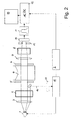
- the light source 1 (LED or semiconductor laser) is made using a device 2 modulated accordingly.
- the optical Optical components (lenses, apertures 3, 5, 7, 9, 14 or Filters 4, 8) can be provided, which are necessary to achieve a measurement parallel beam path optimized or to the individual characteristics of the The object to be measured and the measuring method are coordinated. For example, requires a measurement object 6 with a convex liquid surface has a convergent light beam at the entry surface for vertical photometry.
- optical filters 4, 8 e.g. interference filter, colored glass filter, polarization filter or electro-optical filter
- the measurement object 6 is to be arranged in a suitable form in the beam path.
- liquid or gaseous measurement objects are usually cuvettes made of glass, Quartz or plastic used as the measuring chamber.
- the liquid columns or Gas spaces can radiate in the vertical or horizontal direction become.
- the detector 10 receives the modulated which is weakened by the measurement object optical signal and converts it into a suitable amplifier electrical sine signal around.
- a detection device insensitive to constant light is used become. Suppression is also possible with a suitable amplifier of the constant light component.
- In front of the detector 10 further aperture 14 may be arranged.
- the remaining signal now becomes selective with the frequency of the modulation (narrowband) amplified by one or more AC voltage amplifiers 11.
- the advantage of this method is the narrowing of the amplifier bandwidth required, their minimum size by the expected maximum Rate of change of the measurement results is determined. Usually are these (mostly chemical) change rates so slowly that the bandwidths of the filters are only fractions of the modulation frequency can.
- the modulation device has 2 a sine wave generator (e.g. 10 kHz), which is connected to a voltage / current converter 15 modulates the luminosity of LED 1.
- a reference signal of the sine wave generator is fed to the rectifier 12.
- a reference beam 16 is coupled out and a reference photo sensor 17 supplied, the resulting electrical signal as a control variable for the Voltage / current converter 15 is used.
- an aperiodic (frequency-independent) Rectification for example, an aperiodic (frequency-independent) Rectification, a frequency selective rectification (phase independent or phase selective synchronous rectifier) or a peak value rectification (with Sample and hold).
- aperiodic (frequency-independent) Rectification for example, a frequency-independent
- a frequency selective rectification phase independent or phase selective synchronous rectifier
- a peak value rectification with Sample and hold
- a constant light environment or artificial light (sunlight, artificial lighting with 50 or 60 Hz) has no measurable influence on the measurement result or the Accuracy of measurement, since measurements are carried out with higher-frequency alternating light, whereby a suppression of extraneous light of over 5 orders of magnitude without large Effort can be achieved.
Landscapes
- Physics & Mathematics (AREA)
- Spectroscopy & Molecular Physics (AREA)
- General Physics & Mathematics (AREA)
- Health & Medical Sciences (AREA)
- Life Sciences & Earth Sciences (AREA)
- Chemical & Material Sciences (AREA)
- Analytical Chemistry (AREA)
- Biochemistry (AREA)
- General Health & Medical Sciences (AREA)
- Immunology (AREA)
- Pathology (AREA)
- Investigating Or Analysing Materials By Optical Means (AREA)
Abstract
Description
- Fig. 1
- ein Schema der verwendeten Komponenten, sowie
- Fig. 2
- eine schematische Darstellung einer Vorrichtung zur Durchführung des erfindungsgemäßen Verfahrens.
Claims (9)
- Messverfahren zur Bestimmung der optischen Transmission oder Reflexion sowie davon abgeleiteter Messgrößen, wobei die Messstrahlung ausgehend von einer modulierten Strahlungsquelle nach der Wechselwirkung mit einem Messobjekt von einem Detektor erfasst, in ein elektrisches Signal umgewandelt, frequenzselektiv verstärkt und einer Auswerteeinrichtung zugeführt wird, dadurch gekennzeichnet , dass als Lichtquelle ein Halbleiterlaser oder eine LED verwendet wird, dessen bzw. deren Leuchtstärke sinusförmig moduliert wird.
- Verfahren nach Anspruch 1, dadurch gekennzeichnet, dass die sinusförmige Modulation der Leuchtstärke durch Stromeinprägung und/oder Modulation der Versorgungsspannung der Lichtquelle erfolgt.
- Verfahren nach Anspruch 1, dadurch gekennzeichnet, dass die sinusförmige Modulation der Leuchtstärke durch eine elektrooptische Modulation der Messstrahlung erfolgt.
- Verfahren nach Anspruch 3, dadurch gekennzeichnet, dass für die elektrooptische Modulation ein Filter verwendet wird, dessen optische Transmission elektrisch modulierbar ist.
- Verfahren nach einem der Ansprüche 1 bis 4, dadurch gekennzeichnet, dass die Modulation der Leuchtstärke im gesamten zur Verfügung stehenden linearen Dynamikbereich der Lichtquelle erfolgt.
- Verfahren nach einem der Ansprüche 1 bis 5, dadurch gekennzeichnet, dass eine Modulationsfrequenz > 1 kHz, vorzugsweise > 10 kHz verwendet wird.
- Verfahren nach einem der Ansprüche 1 bis 6, dadurch gekennzeichnet, dass für die Detektion der Messstrahlung eine für Gleichlicht unempfindliche Detektionseinrichtung verwendet wird.
- Verfahren nach einem der Ansprüche 1 bis 7, dadurch gekennzeichnet, dass nach der frequenzselektiven Verstärkung des elektrischen Signals ein Präzisions-Gleichrichter durchlaufen wird.
- Verfahren nach Anspruch 8, dadurch gekennzeichnet, dass eine aperiodische Gleichrichtung, eine frequenzselektive Gleichrichtung, eine phasenselektive Gleichrichtung, oder eine Spitzenwertgleichrichtung durchgeführt wird.
Applications Claiming Priority (2)
| Application Number | Priority Date | Filing Date | Title |
|---|---|---|---|
| AT0022900U AT4201U1 (de) | 2000-03-27 | 2000-03-27 | Messverfahren zur bestimmung der optischen transmission oder reflexion |
| AT2292000U | 2000-03-27 |
Publications (2)
| Publication Number | Publication Date |
|---|---|
| EP1139079A2 true EP1139079A2 (de) | 2001-10-04 |
| EP1139079A3 EP1139079A3 (de) | 2002-12-11 |
Family
ID=3484972
Family Applications (1)
| Application Number | Title | Priority Date | Filing Date |
|---|---|---|---|
| EP01890086A Withdrawn EP1139079A3 (de) | 2000-03-27 | 2001-03-19 | Messverfahren zur Bestimmung der optischen Transmission oder Reflexion |
Country Status (2)
| Country | Link |
|---|---|
| EP (1) | EP1139079A3 (de) |
| AT (1) | AT4201U1 (de) |
Family Cites Families (5)
| Publication number | Priority date | Publication date | Assignee | Title |
|---|---|---|---|---|
| US3735127A (en) * | 1971-09-15 | 1973-05-22 | Barnes Eng Co | Infrared two gas analyzer |
| US4557604A (en) * | 1979-12-26 | 1985-12-10 | Verbatim Corporation | Floppy disk transmissivity meter |
| JP3107927B2 (ja) * | 1992-10-06 | 2000-11-13 | 浜松ホトニクス株式会社 | 散乱吸収体の光学情報計測装置及び方法 |
| NL1002179C2 (nl) * | 1996-01-26 | 1997-07-29 | Stichting Fund Ond Material | Absorptie-spectrometer. |
| JP3844815B2 (ja) * | 1996-08-30 | 2006-11-15 | 浜松ホトニクス株式会社 | 散乱体の吸収情報計測方法及び装置 |
-
2000
- 2000-03-27 AT AT0022900U patent/AT4201U1/de not_active IP Right Cessation
-
2001
- 2001-03-19 EP EP01890086A patent/EP1139079A3/de not_active Withdrawn
Also Published As
| Publication number | Publication date |
|---|---|
| EP1139079A3 (de) | 2002-12-11 |
| AT4201U1 (de) | 2001-03-26 |
Similar Documents
| Publication | Publication Date | Title |
|---|---|---|
| EP1183520B1 (de) | Gassensoranordnung | |
| DE2526794A1 (de) | Gasanalysator | |
| DE2553565B2 (de) | Vorrichtung zur Bestimmung der Stickoxidkonzentration in einem Gasgemisch | |
| DE2940325A1 (de) | Strahlungsmengenmesser | |
| DE3886308T2 (de) | Spektralphotometer. | |
| DE102019126044A1 (de) | Spektrometervorrichtung und Verfahren zur Kalibrierung einer Spektrometervorrichtung | |
| DE3615260A1 (de) | Verfahren und system zur optischen transmissionsmessung | |
| EP0218213B1 (de) | Verfahren und Vorrichtung zur on-line-Messung von Transmission oder Reflexion an bewegten Objekten im Bereich detektierbarer elektromagnetischer Strahlung | |
| DE3620324A1 (de) | Verfahren und vorrichtung zur analyse von atomspektreten | |
| DE3541165C2 (de) | ||
| DE102016108267A1 (de) | Vorrichtung und Verfahren zum Ermitteln einer Konzentration von wenigstens einer Gaskomponente eines Gasgemischs | |
| AT410033B (de) | Verfahren und messeinrichtung zur bestimmung zumindest eines lumineszenz-, floureszenz- oder absorptionsparameters einer probe | |
| CH423274A (de) | Verfahren und Vorrichtung zum automatischen und kontinuierlichen Messen von Schichtdicken | |
| EP0555508B1 (de) | Verfahren und Vorrichtung zur simultanen Bestimmung der Konzentrationen von Molekülverbindungen in Gasen und Flüssigkeiten | |
| DE2507183A1 (de) | Zweistrahlinterferometer zur bestimmung von optischen brechzahlen | |
| AT4201U1 (de) | Messverfahren zur bestimmung der optischen transmission oder reflexion | |
| DE19525415A1 (de) | Verfahren und Vorrichtung zur Bestimmung der Konzentration von Gasen | |
| EP3575759B1 (de) | Spektrometer und verfahren zum betrieb | |
| DE102022104685A1 (de) | Sensor | |
| DD218791A3 (de) | Circulardichroismus (cd)-messgeraet | |
| DE202014105282U1 (de) | Wellenlängen-Modulations-Spektrometer | |
| DE102010062015B4 (de) | Messeinrichtung zur Messung von Absorption oder Streuung bei unterschiedlichen Wellenlängen | |
| DE19849847B4 (de) | Verfahren und Vorrichtung zur präzisen, quantitativen Stoffananlyse in Flüssigkeiten, Gasen und Feststoffen | |
| WO2010106064A1 (de) | Nicht-lineare wellenlängenmodulation bei der laserspektroskopie | |
| EP0538664A2 (de) | Verfahren und Anordnung zur Bestimmung der durch physikalische bzw. chemische Effekte hervorgerufenen optischen Spektralverschiebung |
Legal Events
| Date | Code | Title | Description |
|---|---|---|---|
| PUAI | Public reference made under article 153(3) epc to a published international application that has entered the european phase |
Free format text: ORIGINAL CODE: 0009012 |
|
| AK | Designated contracting states |
Kind code of ref document: A2 Designated state(s): AT BE CH CY DE DK ES FI FR GB GR IE IT LI LU MC NL PT SE TR |
|
| AX | Request for extension of the european patent |
Free format text: AL;LT;LV;MK;RO;SI |
|
| PUAL | Search report despatched |
Free format text: ORIGINAL CODE: 0009013 |
|
| AK | Designated contracting states |
Kind code of ref document: A3 Designated state(s): AT BE CH CY DE DK ES FI FR GB GR IE IT LI LU MC NL PT SE TR |
|
| AX | Request for extension of the european patent |
Free format text: AL;LT;LV;MK;RO;SI |
|
| AKX | Designation fees paid | ||
| REG | Reference to a national code |
Ref country code: DE Ref legal event code: 8566 |
|
| STAA | Information on the status of an ep patent application or granted ep patent |
Free format text: STATUS: THE APPLICATION IS DEEMED TO BE WITHDRAWN |
|
| 18D | Application deemed to be withdrawn |
Effective date: 20030612 |