EP1139092A2 - Feuchtigkeitssensor und dessen Verfahren zur Herstellung - Google Patents
Feuchtigkeitssensor und dessen Verfahren zur Herstellung Download PDFInfo
- Publication number
- EP1139092A2 EP1139092A2 EP01302919A EP01302919A EP1139092A2 EP 1139092 A2 EP1139092 A2 EP 1139092A2 EP 01302919 A EP01302919 A EP 01302919A EP 01302919 A EP01302919 A EP 01302919A EP 1139092 A2 EP1139092 A2 EP 1139092A2
- Authority
- EP
- European Patent Office
- Prior art keywords
- polymer
- humidity
- group
- humidity sensor
- reaction
- Prior art date
- Legal status (The legal status is an assumption and is not a legal conclusion. Google has not performed a legal analysis and makes no representation as to the accuracy of the status listed.)
- Ceased
Links
- 238000000034 method Methods 0.000 title claims description 19
- 229920000642 polymer Polymers 0.000 claims abstract description 339
- 239000010409 thin film Substances 0.000 claims abstract description 65
- -1 silane compound Chemical class 0.000 claims abstract description 50
- 239000000758 substrate Substances 0.000 claims abstract description 44
- 229910000077 silane Inorganic materials 0.000 claims abstract description 18
- 229920001940 conductive polymer Polymers 0.000 claims abstract description 17
- 238000004132 cross linking Methods 0.000 claims description 56
- 150000001875 compounds Chemical class 0.000 claims description 30
- IJGRMHOSHXDMSA-UHFFFAOYSA-N Atomic nitrogen Chemical compound N#N IJGRMHOSHXDMSA-UHFFFAOYSA-N 0.000 claims description 28
- 229910052757 nitrogen Inorganic materials 0.000 claims description 21
- 239000000203 mixture Substances 0.000 claims description 19
- 125000000217 alkyl group Chemical group 0.000 claims description 18
- 230000005855 radiation Effects 0.000 claims description 15
- 125000004429 atom Chemical group 0.000 claims description 14
- 125000003342 alkenyl group Chemical group 0.000 claims description 12
- XUIMIQQOPSSXEZ-UHFFFAOYSA-N Silicon Chemical compound [Si] XUIMIQQOPSSXEZ-UHFFFAOYSA-N 0.000 claims description 10
- 125000002947 alkylene group Chemical group 0.000 claims description 10
- 229910052710 silicon Inorganic materials 0.000 claims description 10
- 239000010703 silicon Substances 0.000 claims description 10
- 125000000962 organic group Chemical group 0.000 claims description 9
- 125000004450 alkenylene group Chemical group 0.000 claims description 8
- 125000000732 arylene group Chemical group 0.000 claims description 8
- 125000004433 nitrogen atom Chemical group N* 0.000 claims description 6
- 125000004435 hydrogen atom Chemical group [H]* 0.000 claims description 4
- 125000002915 carbonyl group Chemical group [*:2]C([*:1])=O 0.000 claims description 3
- 238000005695 dehalogenation reaction Methods 0.000 claims description 3
- 239000001257 hydrogen Substances 0.000 claims description 3
- 229910052739 hydrogen Inorganic materials 0.000 claims description 3
- 125000001820 oxy group Chemical group [*:1]O[*:2] 0.000 claims description 3
- XLYOFNOQVPJJNP-UHFFFAOYSA-N water Substances O XLYOFNOQVPJJNP-UHFFFAOYSA-N 0.000 abstract description 149
- 239000012298 atmosphere Substances 0.000 abstract description 13
- 239000000243 solution Substances 0.000 description 194
- OKKJLVBELUTLKV-UHFFFAOYSA-N Methanol Chemical compound OC OKKJLVBELUTLKV-UHFFFAOYSA-N 0.000 description 168
- 238000006243 chemical reaction Methods 0.000 description 165
- KFZMGEQAYNKOFK-UHFFFAOYSA-N Isopropanol Chemical compound CC(C)O KFZMGEQAYNKOFK-UHFFFAOYSA-N 0.000 description 97
- 238000000576 coating method Methods 0.000 description 92
- 239000011248 coating agent Substances 0.000 description 91
- 238000012360 testing method Methods 0.000 description 81
- CSCPPACGZOOCGX-UHFFFAOYSA-N Acetone Chemical compound CC(C)=O CSCPPACGZOOCGX-UHFFFAOYSA-N 0.000 description 76
- 238000010992 reflux Methods 0.000 description 50
- 239000010410 layer Substances 0.000 description 40
- 239000011521 glass Substances 0.000 description 38
- 239000002244 precipitate Substances 0.000 description 37
- 238000001914 filtration Methods 0.000 description 36
- 238000006116 polymerization reaction Methods 0.000 description 30
- 238000005956 quaternization reaction Methods 0.000 description 28
- RXYPXQSKLGGKOL-UHFFFAOYSA-N 1,4-dimethylpiperazine Chemical compound CN1CCN(C)CC1 RXYPXQSKLGGKOL-UHFFFAOYSA-N 0.000 description 20
- GDFCSMCGLZFNFY-UHFFFAOYSA-N Dimethylaminopropyl Methacrylamide Chemical compound CN(C)CCCNC(=O)C(C)=C GDFCSMCGLZFNFY-UHFFFAOYSA-N 0.000 description 17
- 239000007789 gas Substances 0.000 description 17
- IMNIMPAHZVJRPE-UHFFFAOYSA-N triethylenediamine Chemical compound C1CN2CCN1CC2 IMNIMPAHZVJRPE-UHFFFAOYSA-N 0.000 description 17
- 239000010408 film Substances 0.000 description 16
- 239000000463 material Substances 0.000 description 16
- YHRUOJUYPBUZOS-UHFFFAOYSA-N 1,3-dichloropropane Chemical compound ClCCCCl YHRUOJUYPBUZOS-UHFFFAOYSA-N 0.000 description 15
- WDCYWAQPCXBPJA-UHFFFAOYSA-N 1,3-dinitrobenzene Chemical compound [O-][N+](=O)C1=CC=CC([N+]([O-])=O)=C1 WDCYWAQPCXBPJA-UHFFFAOYSA-N 0.000 description 15
- OVISMSJCKCDOPU-UHFFFAOYSA-N 1,6-dichlorohexane Chemical compound ClCCCCCCCl OVISMSJCKCDOPU-UHFFFAOYSA-N 0.000 description 15
- 239000003112 inhibitor Substances 0.000 description 15
- RAHZWNYVWXNFOC-UHFFFAOYSA-N Sulphur dioxide Chemical compound O=S=O RAHZWNYVWXNFOC-UHFFFAOYSA-N 0.000 description 12
- 230000000052 comparative effect Effects 0.000 description 12
- 125000004432 carbon atom Chemical group C* 0.000 description 11
- LFQSCWFLJHTTHZ-UHFFFAOYSA-N Ethanol Chemical compound CCO LFQSCWFLJHTTHZ-UHFFFAOYSA-N 0.000 description 10
- ZNQVEEAIQZEUHB-UHFFFAOYSA-N 2-ethoxyethanol Chemical compound CCOCCO ZNQVEEAIQZEUHB-UHFFFAOYSA-N 0.000 description 9
- 229940093475 2-ethoxyethanol Drugs 0.000 description 9
- TXXWBTOATXBWDR-UHFFFAOYSA-N n,n,n',n'-tetramethylhexane-1,6-diamine Chemical compound CN(C)CCCCCCN(C)C TXXWBTOATXBWDR-UHFFFAOYSA-N 0.000 description 9
- JCXJVPUVTGWSNB-UHFFFAOYSA-N nitrogen dioxide Inorganic materials O=[N]=O JCXJVPUVTGWSNB-UHFFFAOYSA-N 0.000 description 9
- 150000003242 quaternary ammonium salts Chemical group 0.000 description 9
- 238000003756 stirring Methods 0.000 description 9
- 239000000047 product Substances 0.000 description 7
- SLBOQBILGNEPEB-UHFFFAOYSA-N 1-chloroprop-2-enylbenzene Chemical compound C=CC(Cl)C1=CC=CC=C1 SLBOQBILGNEPEB-UHFFFAOYSA-N 0.000 description 6
- QTBSBXVTEAMEQO-UHFFFAOYSA-N Acetic acid Chemical compound CC(O)=O QTBSBXVTEAMEQO-UHFFFAOYSA-N 0.000 description 6
- 125000002496 methyl group Chemical group [H]C([H])([H])* 0.000 description 6
- KZBUYRJDOAKODT-UHFFFAOYSA-N Chlorine Chemical compound ClCl KZBUYRJDOAKODT-UHFFFAOYSA-N 0.000 description 5
- 150000004985 diamines Chemical class 0.000 description 5
- 239000003792 electrolyte Substances 0.000 description 5
- 125000002887 hydroxy group Chemical group [H]O* 0.000 description 5
- ADTJPOBHAXXXFS-UHFFFAOYSA-N n-[3-(dimethylamino)propyl]prop-2-enamide Chemical compound CN(C)CCCNC(=O)C=C ADTJPOBHAXXXFS-UHFFFAOYSA-N 0.000 description 5
- 239000002904 solvent Substances 0.000 description 5
- 239000000126 substance Substances 0.000 description 5
- 125000001424 substituent group Chemical group 0.000 description 5
- 229940051269 1,3-dichloro-2-propanol Drugs 0.000 description 4
- DEWLEGDTCGBNGU-UHFFFAOYSA-N 1,3-dichloropropan-2-ol Chemical compound ClCC(O)CCl DEWLEGDTCGBNGU-UHFFFAOYSA-N 0.000 description 4
- 125000003903 2-propenyl group Chemical group [H]C([*])([H])C([H])=C([H])[H] 0.000 description 4
- 206010073306 Exposure to radiation Diseases 0.000 description 4
- JUJWROOIHBZHMG-UHFFFAOYSA-N Pyridine Chemical compound C1=CC=NC=C1 JUJWROOIHBZHMG-UHFFFAOYSA-N 0.000 description 4
- 239000010931 gold Substances 0.000 description 4
- 125000005843 halogen group Chemical group 0.000 description 4
- KWGKDLIKAYFUFQ-UHFFFAOYSA-M lithium chloride Chemical compound [Li+].[Cl-] KWGKDLIKAYFUFQ-UHFFFAOYSA-M 0.000 description 4
- 238000005259 measurement Methods 0.000 description 4
- 239000005871 repellent Substances 0.000 description 4
- WOCIAKWEIIZHES-UHFFFAOYSA-N ruthenium(iv) oxide Chemical compound O=[Ru]=O WOCIAKWEIIZHES-UHFFFAOYSA-N 0.000 description 4
- JWOTWWORMYMZCR-UHFFFAOYSA-N 1-methyl-4-[3-(1-methylpiperidin-4-yl)propyl]piperidine Chemical compound C1CN(C)CCC1CCCC1CCN(C)CC1 JWOTWWORMYMZCR-UHFFFAOYSA-N 0.000 description 3
- MGWGWNFMUOTEHG-UHFFFAOYSA-N 4-(3,5-dimethylphenyl)-1,3-thiazol-2-amine Chemical compound CC1=CC(C)=CC(C=2N=C(N)SC=2)=C1 MGWGWNFMUOTEHG-UHFFFAOYSA-N 0.000 description 3
- ZAMOUSCENKQFHK-UHFFFAOYSA-N Chlorine atom Chemical compound [Cl] ZAMOUSCENKQFHK-UHFFFAOYSA-N 0.000 description 3
- 229940126062 Compound A Drugs 0.000 description 3
- XEKOWRVHYACXOJ-UHFFFAOYSA-N Ethyl acetate Chemical compound CCOC(C)=O XEKOWRVHYACXOJ-UHFFFAOYSA-N 0.000 description 3
- NLDMNSXOCDLTTB-UHFFFAOYSA-N Heterophylliin A Natural products O1C2COC(=O)C3=CC(O)=C(O)C(O)=C3C3=C(O)C(O)=C(O)C=C3C(=O)OC2C(OC(=O)C=2C=C(O)C(O)=C(O)C=2)C(O)C1OC(=O)C1=CC(O)=C(O)C(O)=C1 NLDMNSXOCDLTTB-UHFFFAOYSA-N 0.000 description 3
- 125000005336 allyloxy group Chemical group 0.000 description 3
- 125000003277 amino group Chemical group 0.000 description 3
- 239000000460 chlorine Substances 0.000 description 3
- 229910052801 chlorine Inorganic materials 0.000 description 3
- 238000009792 diffusion process Methods 0.000 description 3
- 239000005518 polymer electrolyte Substances 0.000 description 3
- 238000007650 screen-printing Methods 0.000 description 3
- 125000000391 vinyl group Chemical group [H]C([*])=C([H])[H] 0.000 description 3
- 229920002554 vinyl polymer Polymers 0.000 description 3
- XNWFRZJHXBZDAG-UHFFFAOYSA-N 2-METHOXYETHANOL Chemical compound COCCO XNWFRZJHXBZDAG-UHFFFAOYSA-N 0.000 description 2
- OGNCVVRIKNGJHQ-UHFFFAOYSA-N 4-(3-pyridin-4-ylpropyl)pyridine Chemical compound C=1C=NC=CC=1CCCC1=CC=NC=C1 OGNCVVRIKNGJHQ-UHFFFAOYSA-N 0.000 description 2
- CPELXLSAUQHCOX-UHFFFAOYSA-M Bromide Chemical compound [Br-] CPELXLSAUQHCOX-UHFFFAOYSA-M 0.000 description 2
- GLUUGHFHXGJENI-UHFFFAOYSA-N Piperazine Chemical compound C1CNCCN1 GLUUGHFHXGJENI-UHFFFAOYSA-N 0.000 description 2
- NQRYJNQNLNOLGT-UHFFFAOYSA-N Piperidine Chemical compound C1CCNCC1 NQRYJNQNLNOLGT-UHFFFAOYSA-N 0.000 description 2
- NIXOWILDQLNWCW-UHFFFAOYSA-N acrylic acid group Chemical group C(C=C)(=O)O NIXOWILDQLNWCW-UHFFFAOYSA-N 0.000 description 2
- 150000001298 alcohols Chemical class 0.000 description 2
- 125000003545 alkoxy group Chemical group 0.000 description 2
- 125000003917 carbamoyl group Chemical group [H]N([H])C(*)=O 0.000 description 2
- 229910052799 carbon Inorganic materials 0.000 description 2
- 239000000919 ceramic Substances 0.000 description 2
- 239000007795 chemical reaction product Substances 0.000 description 2
- 230000001351 cycling effect Effects 0.000 description 2
- 238000007598 dipping method Methods 0.000 description 2
- 239000012153 distilled water Substances 0.000 description 2
- 239000007772 electrode material Substances 0.000 description 2
- NKSJNEHGWDZZQF-UHFFFAOYSA-N ethenyl(trimethoxy)silane Chemical compound CO[Si](OC)(OC)C=C NKSJNEHGWDZZQF-UHFFFAOYSA-N 0.000 description 2
- 125000001495 ethyl group Chemical group [H]C([H])([H])C([H])([H])* 0.000 description 2
- 238000010304 firing Methods 0.000 description 2
- 238000010438 heat treatment Methods 0.000 description 2
- 125000000623 heterocyclic group Chemical group 0.000 description 2
- 230000007062 hydrolysis Effects 0.000 description 2
- 238000006460 hydrolysis reaction Methods 0.000 description 2
- 150000002500 ions Chemical class 0.000 description 2
- 239000007788 liquid Substances 0.000 description 2
- 230000007774 longterm Effects 0.000 description 2
- 229910044991 metal oxide Inorganic materials 0.000 description 2
- 150000004706 metal oxides Chemical class 0.000 description 2
- 125000005395 methacrylic acid group Chemical group 0.000 description 2
- 239000000178 monomer Substances 0.000 description 2
- QJGQUHMNIGDVPM-UHFFFAOYSA-N nitrogen group Chemical group [N] QJGQUHMNIGDVPM-UHFFFAOYSA-N 0.000 description 2
- 229920000620 organic polymer Polymers 0.000 description 2
- 239000003505 polymerization initiator Substances 0.000 description 2
- UMJSCPRVCHMLSP-UHFFFAOYSA-N pyridine Natural products COC1=CC=CN=C1 UMJSCPRVCHMLSP-UHFFFAOYSA-N 0.000 description 2
- 125000001453 quaternary ammonium group Chemical group 0.000 description 2
- 239000000376 reactant Substances 0.000 description 2
- 229910000679 solder Inorganic materials 0.000 description 2
- 238000005476 soldering Methods 0.000 description 2
- 238000003860 storage Methods 0.000 description 2
- QNODIIQQMGDSEF-UHFFFAOYSA-N (1-hydroxycyclohexyl)-phenylmethanone Chemical compound C=1C=CC=CC=1C(=O)C1(O)CCCCC1 QNODIIQQMGDSEF-UHFFFAOYSA-N 0.000 description 1
- RNXPZVYZVHJVHM-UHFFFAOYSA-N 1,12-dichlorododecane Chemical compound ClCCCCCCCCCCCCCl RNXPZVYZVHJVHM-UHFFFAOYSA-N 0.000 description 1
- KIHQZLPHVZKELA-UHFFFAOYSA-N 1,3-dibromopropan-2-ol Chemical compound BrCC(O)CBr KIHQZLPHVZKELA-UHFFFAOYSA-N 0.000 description 1
- VEFLKXRACNJHOV-UHFFFAOYSA-N 1,3-dibromopropane Chemical compound BrCCCBr VEFLKXRACNJHOV-UHFFFAOYSA-N 0.000 description 1
- LBKDGROORAKTLC-UHFFFAOYSA-N 1,5-dichloropentane Chemical compound ClCCCCCCl LBKDGROORAKTLC-UHFFFAOYSA-N 0.000 description 1
- REEBWSYYNPPSKV-UHFFFAOYSA-N 3-[(4-formylphenoxy)methyl]thiophene-2-carbonitrile Chemical compound C1=CC(C=O)=CC=C1OCC1=C(C#N)SC=C1 REEBWSYYNPPSKV-UHFFFAOYSA-N 0.000 description 1
- DOYKFSOCSXVQAN-UHFFFAOYSA-N 3-[diethoxy(methyl)silyl]propyl 2-methylprop-2-enoate Chemical compound CCO[Si](C)(OCC)CCCOC(=O)C(C)=C DOYKFSOCSXVQAN-UHFFFAOYSA-N 0.000 description 1
- LZMNXXQIQIHFGC-UHFFFAOYSA-N 3-[dimethoxy(methyl)silyl]propyl 2-methylprop-2-enoate Chemical compound CO[Si](C)(OC)CCCOC(=O)C(C)=C LZMNXXQIQIHFGC-UHFFFAOYSA-N 0.000 description 1
- URDOJQUSEUXVRP-UHFFFAOYSA-N 3-triethoxysilylpropyl 2-methylprop-2-enoate Chemical compound CCO[Si](OCC)(OCC)CCCOC(=O)C(C)=C URDOJQUSEUXVRP-UHFFFAOYSA-N 0.000 description 1
- XDLMVUHYZWKMMD-UHFFFAOYSA-N 3-trimethoxysilylpropyl 2-methylprop-2-enoate Chemical compound CO[Si](OC)(OC)CCCOC(=O)C(C)=C XDLMVUHYZWKMMD-UHFFFAOYSA-N 0.000 description 1
- ZCYVEMRRCGMTRW-UHFFFAOYSA-N 7553-56-2 Chemical compound [I] ZCYVEMRRCGMTRW-UHFFFAOYSA-N 0.000 description 1
- QGZKDVFQNNGYKY-UHFFFAOYSA-O Ammonium Chemical compound [NH4+] QGZKDVFQNNGYKY-UHFFFAOYSA-O 0.000 description 1
- WKBOTKDWSSQWDR-UHFFFAOYSA-N Bromine atom Chemical compound [Br] WKBOTKDWSSQWDR-UHFFFAOYSA-N 0.000 description 1
- VEXZGXHMUGYJMC-UHFFFAOYSA-M Chloride anion Chemical compound [Cl-] VEXZGXHMUGYJMC-UHFFFAOYSA-M 0.000 description 1
- 239000004593 Epoxy Substances 0.000 description 1
- VEXZGXHMUGYJMC-UHFFFAOYSA-N Hydrochloric acid Chemical compound Cl VEXZGXHMUGYJMC-UHFFFAOYSA-N 0.000 description 1
- KWYHDKDOAIKMQN-UHFFFAOYSA-N N,N,N',N'-tetramethylethylenediamine Chemical compound CN(C)CCN(C)C KWYHDKDOAIKMQN-UHFFFAOYSA-N 0.000 description 1
- 229910001252 Pd alloy Inorganic materials 0.000 description 1
- 239000004698 Polyethylene Substances 0.000 description 1
- 239000004743 Polypropylene Substances 0.000 description 1
- 239000005700 Putrescine Substances 0.000 description 1
- 229910008051 Si-OH Inorganic materials 0.000 description 1
- 239000006087 Silane Coupling Agent Substances 0.000 description 1
- 229910006358 Si—OH Inorganic materials 0.000 description 1
- LOPVAWVHGAWUPS-UHFFFAOYSA-M [2-hydroxy-3-(2-methylprop-2-enoyloxy)propyl]-trimethylazanium;chloride Chemical compound [Cl-].CC(=C)C(=O)OCC(O)C[N+](C)(C)C LOPVAWVHGAWUPS-UHFFFAOYSA-M 0.000 description 1
- 125000003668 acetyloxy group Chemical group [H]C([H])([H])C(=O)O[*] 0.000 description 1
- 238000007605 air drying Methods 0.000 description 1
- PNEYBMLMFCGWSK-UHFFFAOYSA-N aluminium oxide Inorganic materials [O-2].[O-2].[O-2].[Al+3].[Al+3] PNEYBMLMFCGWSK-UHFFFAOYSA-N 0.000 description 1
- 125000003368 amide group Chemical group 0.000 description 1
- 239000007864 aqueous solution Substances 0.000 description 1
- 239000003125 aqueous solvent Substances 0.000 description 1
- 239000012965 benzophenone Substances 0.000 description 1
- 230000015572 biosynthetic process Effects 0.000 description 1
- GDTBXPJZTBHREO-UHFFFAOYSA-N bromine Substances BrBr GDTBXPJZTBHREO-UHFFFAOYSA-N 0.000 description 1
- 229910052794 bromium Inorganic materials 0.000 description 1
- 125000001246 bromo group Chemical group Br* 0.000 description 1
- 125000004369 butenyl group Chemical group C(=CCC)* 0.000 description 1
- 125000000484 butyl group Chemical group [H]C([*])([H])C([H])([H])C([H])([H])C([H])([H])[H] 0.000 description 1
- 150000001767 cationic compounds Chemical class 0.000 description 1
- 150000001768 cations Chemical class 0.000 description 1
- 230000008859 change Effects 0.000 description 1
- 125000001309 chloro group Chemical group Cl* 0.000 description 1
- 238000004140 cleaning Methods 0.000 description 1
- 238000009833 condensation Methods 0.000 description 1
- 230000005494 condensation Effects 0.000 description 1
- 238000010276 construction Methods 0.000 description 1
- 229920001577 copolymer Polymers 0.000 description 1
- 230000007423 decrease Effects 0.000 description 1
- 230000003247 decreasing effect Effects 0.000 description 1
- 238000006297 dehydration reaction Methods 0.000 description 1
- SOCTUWSJJQCPFX-UHFFFAOYSA-N dichromate(2-) Chemical compound [O-][Cr](=O)(=O)O[Cr]([O-])(=O)=O SOCTUWSJJQCPFX-UHFFFAOYSA-N 0.000 description 1
- 238000010494 dissociation reaction Methods 0.000 description 1
- 230000005593 dissociations Effects 0.000 description 1
- 238000001035 drying Methods 0.000 description 1
- FWDBOZPQNFPOLF-UHFFFAOYSA-N ethenyl(triethoxy)silane Chemical compound CCO[Si](OCC)(OCC)C=C FWDBOZPQNFPOLF-UHFFFAOYSA-N 0.000 description 1
- WOXXJEVNDJOOLV-UHFFFAOYSA-N ethenyl-tris(2-methoxyethoxy)silane Chemical compound COCCO[Si](OCCOC)(OCCOC)C=C WOXXJEVNDJOOLV-UHFFFAOYSA-N 0.000 description 1
- 125000001301 ethoxy group Chemical group [H]C([H])([H])C([H])([H])O* 0.000 description 1
- RRLWYLINGKISHN-UHFFFAOYSA-N ethoxymethanol Chemical compound CCOCO RRLWYLINGKISHN-UHFFFAOYSA-N 0.000 description 1
- 239000012467 final product Substances 0.000 description 1
- 229920002313 fluoropolymer Polymers 0.000 description 1
- PCHJSUWPFVWCPO-UHFFFAOYSA-N gold Chemical compound [Au] PCHJSUWPFVWCPO-UHFFFAOYSA-N 0.000 description 1
- 229910052737 gold Inorganic materials 0.000 description 1
- 238000007756 gravure coating Methods 0.000 description 1
- 150000004820 halides Chemical group 0.000 description 1
- 229910052736 halogen Inorganic materials 0.000 description 1
- 150000002367 halogens Chemical group 0.000 description 1
- 230000005660 hydrophilic surface Effects 0.000 description 1
- 230000002209 hydrophobic effect Effects 0.000 description 1
- 229920001600 hydrophobic polymer Polymers 0.000 description 1
- 238000007654 immersion Methods 0.000 description 1
- 239000011810 insulating material Substances 0.000 description 1
- 229910052740 iodine Inorganic materials 0.000 description 1
- 239000011630 iodine Substances 0.000 description 1
- 230000001678 irradiating effect Effects 0.000 description 1
- 239000004816 latex Substances 0.000 description 1
- 229920000126 latex Polymers 0.000 description 1
- QSHDDOUJBYECFT-UHFFFAOYSA-N mercury Chemical compound [Hg] QSHDDOUJBYECFT-UHFFFAOYSA-N 0.000 description 1
- 229910052753 mercury Inorganic materials 0.000 description 1
- 239000002184 metal Substances 0.000 description 1
- 229910052751 metal Inorganic materials 0.000 description 1
- 150000002739 metals Chemical class 0.000 description 1
- 125000000956 methoxy group Chemical group [H]C([H])([H])O* 0.000 description 1
- 230000004048 modification Effects 0.000 description 1
- 238000012986 modification Methods 0.000 description 1
- 238000012544 monitoring process Methods 0.000 description 1
- RCZLVPFECJNLMZ-UHFFFAOYSA-N n,n,n',n'-tetraethylpropane-1,3-diamine Chemical compound CCN(CC)CCCN(CC)CC RCZLVPFECJNLMZ-UHFFFAOYSA-N 0.000 description 1
- WYRJQOPVEMCABI-UHFFFAOYSA-N n,n,n',n'-tetrakis(prop-2-enyl)butane-1,4-diamine Chemical compound C=CCN(CC=C)CCCCN(CC=C)CC=C WYRJQOPVEMCABI-UHFFFAOYSA-N 0.000 description 1
- 239000012299 nitrogen atmosphere Substances 0.000 description 1
- 150000002923 oximes Chemical class 0.000 description 1
- 239000002245 particle Substances 0.000 description 1
- 230000035515 penetration Effects 0.000 description 1
- 229920003023 plastic Polymers 0.000 description 1
- 239000004033 plastic Substances 0.000 description 1
- 229920000573 polyethylene Polymers 0.000 description 1
- 230000000379 polymerizing effect Effects 0.000 description 1
- 229920001155 polypropylene Polymers 0.000 description 1
- 229920001296 polysiloxane Polymers 0.000 description 1
- 229920001343 polytetrafluoroethylene Polymers 0.000 description 1
- 239000004810 polytetrafluoroethylene Substances 0.000 description 1
- 229920000036 polyvinylpyrrolidone Polymers 0.000 description 1
- 239000001267 polyvinylpyrrolidone Substances 0.000 description 1
- 235000013855 polyvinylpyrrolidone Nutrition 0.000 description 1
- 238000001556 precipitation Methods 0.000 description 1
- 125000002924 primary amino group Chemical group [H]N([H])* 0.000 description 1
- 230000008569 process Effects 0.000 description 1
- 230000002035 prolonged effect Effects 0.000 description 1
- 125000004368 propenyl group Chemical group C(=CC)* 0.000 description 1
- 125000001436 propyl group Chemical group [H]C([*])([H])C([H])([H])C([H])([H])[H] 0.000 description 1
- 238000000746 purification Methods 0.000 description 1
- 125000003373 pyrazinyl group Chemical group 0.000 description 1
- 230000004044 response Effects 0.000 description 1
- 150000004756 silanes Chemical class 0.000 description 1
- 125000005372 silanol group Chemical group 0.000 description 1
- 239000002210 silicon-based material Substances 0.000 description 1
- 229920005573 silicon-containing polymer Polymers 0.000 description 1
- 238000001179 sorption measurement Methods 0.000 description 1
- 238000004528 spin coating Methods 0.000 description 1
- 239000002344 surface layer Substances 0.000 description 1
- TXEYQDLBPFQVAA-UHFFFAOYSA-N tetrafluoromethane Chemical class FC(F)(F)F TXEYQDLBPFQVAA-UHFFFAOYSA-N 0.000 description 1
- 238000004506 ultrasonic cleaning Methods 0.000 description 1
- 238000005406 washing Methods 0.000 description 1
- 238000009736 wetting Methods 0.000 description 1
Images














Classifications
-
- G—PHYSICS
- G01—MEASURING; TESTING
- G01N—INVESTIGATING OR ANALYSING MATERIALS BY DETERMINING THEIR CHEMICAL OR PHYSICAL PROPERTIES
- G01N27/00—Investigating or analysing materials by the use of electric, electrochemical, or magnetic means
- G01N27/02—Investigating or analysing materials by the use of electric, electrochemical, or magnetic means by investigating impedance
- G01N27/04—Investigating or analysing materials by the use of electric, electrochemical, or magnetic means by investigating impedance by investigating resistance
- G01N27/12—Investigating or analysing materials by the use of electric, electrochemical, or magnetic means by investigating impedance by investigating resistance of a solid body in dependence upon absorption of a fluid; of a solid body in dependence upon reaction with a fluid, for detecting components in the fluid
-
- G—PHYSICS
- G01—MEASURING; TESTING
- G01N—INVESTIGATING OR ANALYSING MATERIALS BY DETERMINING THEIR CHEMICAL OR PHYSICAL PROPERTIES
- G01N27/00—Investigating or analysing materials by the use of electric, electrochemical, or magnetic means
- G01N27/02—Investigating or analysing materials by the use of electric, electrochemical, or magnetic means by investigating impedance
- G01N27/04—Investigating or analysing materials by the use of electric, electrochemical, or magnetic means by investigating impedance by investigating resistance
- G01N27/12—Investigating or analysing materials by the use of electric, electrochemical, or magnetic means by investigating impedance by investigating resistance of a solid body in dependence upon absorption of a fluid; of a solid body in dependence upon reaction with a fluid, for detecting components in the fluid
- G01N27/125—Composition of the body, e.g. the composition of its sensitive layer
- G01N27/126—Composition of the body, e.g. the composition of its sensitive layer comprising organic polymers
-
- G—PHYSICS
- G01—MEASURING; TESTING
- G01N—INVESTIGATING OR ANALYSING MATERIALS BY DETERMINING THEIR CHEMICAL OR PHYSICAL PROPERTIES
- G01N27/00—Investigating or analysing materials by the use of electric, electrochemical, or magnetic means
- G01N27/02—Investigating or analysing materials by the use of electric, electrochemical, or magnetic means by investigating impedance
- G01N27/04—Investigating or analysing materials by the use of electric, electrochemical, or magnetic means by investigating impedance by investigating resistance
- G01N27/12—Investigating or analysing materials by the use of electric, electrochemical, or magnetic means by investigating impedance by investigating resistance of a solid body in dependence upon absorption of a fluid; of a solid body in dependence upon reaction with a fluid, for detecting components in the fluid
- G01N27/121—Investigating or analysing materials by the use of electric, electrochemical, or magnetic means by investigating impedance by investigating resistance of a solid body in dependence upon absorption of a fluid; of a solid body in dependence upon reaction with a fluid, for detecting components in the fluid for determining moisture content, e.g. humidity, of the fluid
-
- Y—GENERAL TAGGING OF NEW TECHNOLOGICAL DEVELOPMENTS; GENERAL TAGGING OF CROSS-SECTIONAL TECHNOLOGIES SPANNING OVER SEVERAL SECTIONS OF THE IPC; TECHNICAL SUBJECTS COVERED BY FORMER USPC CROSS-REFERENCE ART COLLECTIONS [XRACs] AND DIGESTS
- Y10—TECHNICAL SUBJECTS COVERED BY FORMER USPC
- Y10T—TECHNICAL SUBJECTS COVERED BY FORMER US CLASSIFICATION
- Y10T428/00—Stock material or miscellaneous articles
- Y10T428/26—Web or sheet containing structurally defined element or component, the element or component having a specified physical dimension
-
- Y—GENERAL TAGGING OF NEW TECHNOLOGICAL DEVELOPMENTS; GENERAL TAGGING OF CROSS-SECTIONAL TECHNOLOGIES SPANNING OVER SEVERAL SECTIONS OF THE IPC; TECHNICAL SUBJECTS COVERED BY FORMER USPC CROSS-REFERENCE ART COLLECTIONS [XRACs] AND DIGESTS
- Y10—TECHNICAL SUBJECTS COVERED BY FORMER USPC
- Y10T—TECHNICAL SUBJECTS COVERED BY FORMER US CLASSIFICATION
- Y10T428/00—Stock material or miscellaneous articles
- Y10T428/26—Web or sheet containing structurally defined element or component, the element or component having a specified physical dimension
- Y10T428/263—Coating layer not in excess of 5 mils thick or equivalent
- Y10T428/264—Up to 3 mils
- Y10T428/265—1 mil or less
-
- Y—GENERAL TAGGING OF NEW TECHNOLOGICAL DEVELOPMENTS; GENERAL TAGGING OF CROSS-SECTIONAL TECHNOLOGIES SPANNING OVER SEVERAL SECTIONS OF THE IPC; TECHNICAL SUBJECTS COVERED BY FORMER USPC CROSS-REFERENCE ART COLLECTIONS [XRACs] AND DIGESTS
- Y10—TECHNICAL SUBJECTS COVERED BY FORMER USPC
- Y10T—TECHNICAL SUBJECTS COVERED BY FORMER US CLASSIFICATION
- Y10T428/00—Stock material or miscellaneous articles
- Y10T428/31504—Composite [nonstructural laminate]
- Y10T428/31652—Of asbestos
- Y10T428/31663—As siloxane, silicone or silane
-
- Y—GENERAL TAGGING OF NEW TECHNOLOGICAL DEVELOPMENTS; GENERAL TAGGING OF CROSS-SECTIONAL TECHNOLOGIES SPANNING OVER SEVERAL SECTIONS OF THE IPC; TECHNICAL SUBJECTS COVERED BY FORMER USPC CROSS-REFERENCE ART COLLECTIONS [XRACs] AND DIGESTS
- Y10—TECHNICAL SUBJECTS COVERED BY FORMER USPC
- Y10T—TECHNICAL SUBJECTS COVERED BY FORMER US CLASSIFICATION
- Y10T428/00—Stock material or miscellaneous articles
- Y10T428/31504—Composite [nonstructural laminate]
- Y10T428/31855—Of addition polymer from unsaturated monomers
- Y10T428/31938—Polymer of monoethylenically unsaturated hydrocarbon
Definitions
- This invention relates to a humidity sensor for detecting and determining moisture in the surrounding atmosphere and a method for preparing the same.
- Conventional humidity sensors are designed to detect humidity through changes of electrical properties, typically electric resistance.
- Known sensors use electrolytes such as lithium chloride, metal oxides, and organic polymers as the humidity sensitive material.
- electrolytes such as lithium chloride
- metal oxides can measure only a narrow range of humidity and are less resistant to water in that their performance can be altered by dew condensation and wetting.
- the humidity sensors using metal oxides are resistant to water, but low sensitive. Because of the lack of long-term stalbility when used alone, they require a heat cleaning circuit which would add to the operating cost.
- the sensor structure is complex.
- JP-B Japanese Patent Publication
- JP-B No. 61-54176 discloses a humidity sensitive material comprising aggregates of latex particles formed of a copolymer between a hydrophobic monomer and an ionic or non-ionic hydrophilic monomer and having a hydrophilic surface layer.
- cationic compounds having primary to quaternary ammonium salts.
- JP-B 62-7976 discloses a humidity sensitive material in the form of a polymer which is obtained by polymerizing a compound containing 2-hydroxy-3-methacryloxypropyltrimethylammonium chloride to a degree of polymerization of 1,000 to 10,000.
- JP-B 2-24465 discloses a humidity sensitive thin film of a polymer having the structural formula: - (N + (R 1 ) (R 2 )X - -A-N + (R 3 )(R 4 )X - -B) n - wherein R 1 to R 4 are alkyl, X - is a halide ion, A and B each are -(CH 2 ) m - wherein m ⁇ 2.
- the polymer may be blended with another polymer such as polyvinyl pyrrolidone for the purposes of improving substrate adhesion and water resistance. The blend is also effective in forming a humidity sensitive thin film.
- Humidity sensors using the polymeric electrolytes exemplified above as the humidity sensitive material are still low in water resistance in that the polymeric electrolytes can be partially leached in a high humidity region, especially in a dew condensing atmosphere. They also suffer from a hysteresis phenomenon that they produce different outputs at the same humidity depending on whether the humidity is increasing or decreasing. In a low humidity region having a relative humidity (RH) of less than 10%, they have so high resistance values that practical humidity measurement is impossible.
- RH relative humidity
- US Patent No. 5,546,802 (corresponding Japanese Patent No. 2,808,255 by TDK Corp.) discloses a humidity sensor comprising a polymer electrolyte having ethylenically unsaturated reactive groups introduced at ends and quaternary ammonium salt groups. This sensor is fully resistant to water, steadily operates in a condensing atmosphere and produces consistent outputs over a wide humidity region.
- the thickness of the humidity sensitive film must be restricted below a certain limit.
- Such a thin film is so sensitive to various gases that the output characteristics largely vary therewith. Therefore, the sensor has the drawback of lacking long-term stability under hot humid conditions. If the thickness of the humidity sensitive film is increased beyond the limit, stripping and failure are likely to occur.
- a primary object of the present invention is to provide a humidity sensor device having a humidity sensitive thin film which is resistant to water, maintains effective, stable performance over a long time even in a dew condensing atmosphere, and produces accurate outputs in a stable manner over a wide humidity region.
- the invention provides a humidity sensor comprising an insulating substrate, a pair of opposed electrodes disposed on the substrate and defining a gap therebetween, a silicon-containing undercoat layer lying on at least the gap, and a humidity sensitive thin film lying thereon.
- the humidity sensitive thin film comprises a crosslinked product of a conductive polymer having ethylenically unsaturated groups and is physically bound to the undercoat layer through an interpenetrating polymer network.
- the invention provides a humidity sensor comprising an insulating substrate, a pair of opposed electrodes disposed on the substrate and defining a gap therebetween, a silicon-containing undercoat layer lying on at least the gap, and a humidity sensitive thin film lying thereon.
- the humidity sensitive thin film comprises a crosslinked product of a polymer of the following formula (I) and is bound to said undercoat layer through covalent bonds having not undergone dehalogenation reaction.
- a and B each are a divalent group; Y 1 , Y 2 , Y 3 , Y 4 , Y 5 and Y 6 each are a monovalent group, at least one of Y 1 to Y 6 is a group terminated with an ethylenically unsaturated reactive group; at least two of Y 1 , Y 2 , Y 3 , Y 4 , Y 5 , A and portions thereof adjoining the nitrogen (N) atom or at least two of Y 4 , Y 5 , Y 6 , B and portions thereof adjoining the nitrogen (N) atom, taken together, may form a ring with the nitrogen atom; X - is a halide ion; and letter n is a number of 2 to 5,000.
- the humidity sensitive thin film of the second embodiment is physically bound to said undercoat layer through an interpenetrating polymer network.
- the humidity sensitive thin film has a thickness of 0.1 to 20 ⁇ m.
- the polymer has the following formula (II) or (III).
- a and B each are a divalent group; each of R 1 , R 2 , R 3 , and R 4 is an alkyl or alkenyl group; a pair of R 1 and R 2 , R 1 and A or a portion of A, R 2 and A or a portion of A, R 3 and R 4 , R 3 and A or a portion of A, R 4 and A or a portion of A, R 1 and R 3 , R 1 and R 4 , R 2 and R 3 , or R 2 and R 4 , taken together, may form a ring with the nitrogen (N) atom;
- L is a divalent group;
- R is hydrogen or an alkyl group;
- X - is a halide ion;
- n is a number of 2 to 5,000; and
- R 5 and R 6 each are an alkyl or alkenyl group.
- the divalent group represented by A is an alkylene, alkenylene or arylene group or a mixture thereof;
- the divalent group represented by B is an alkylene, alkenylene or arylene group in which at least one of an oxy group (-O-) and a carbonyl group (-CO-) may intervene or a mixture thereof.
- the polymer is typically obtained by reacting a diamine compound with a dihalogen compound to form an intermediate polymer and introducing an ethylenically unsaturated reactive group into the intermediate polymer at each end.
- the invention provides a method for preparing a humidity sensor comprising the steps of:
- the bond between the conductive polymer and the silane compound is due to covalent bonds by crosslinking between the ethylenically unsaturated groups and the unsaturated bonds.
- the radiation is ultraviolet radiation.
- the conductive polymer used herein has the formula (I) defined above.
- a and B each are a divalent group; Y 1 , Y 2 , Y 3 , Y 4 , Y 5 and Y 6 each are a monovalent group, at least one of Y 1 to Y 6 is a group terminated with an ethylenically unsaturated reactive group; at least two of Y 1 , Y 2 , Y 3 , Y 4 , Y 5 , A and portions thereof adjoining the nitrogen (N) atom or at least two of Y 4 , Y 5 , Y 6 , B and portions thereof adjoining the nitrogen (N) atom, taken together, may form a ring with the nitrogen atom; X - is a halide ion; and letter n is a number of 2 to 5,000.
- the silane compound has the following formula (IV): X 0 n (CH 3 ) 3-n Si-R 0 wherein X 0 is a hydrolyzable group, R 0 is an organic group, and n is an integer of 1, 2 or 3.
- an undercoat layer having unsaturated bonds connected via silicon covers a pair of opposed electrodes on an insulating substrate, and a humidity sensitive layer of a conductive polymer of any of formulas (I) to (III) lies thereon.
- the undercoat layer comprising a compound having an unsaturated bond connected via silicon, preferably of formula (IV) is provided for the purpose of establishing a firm or intimate bond between the overlying humidity sensitive layer of conductive polymer and the underlying substrate and electrodes.
- the compound is typically selected from silane coupling agents or silane compounds having vinyl, methacrylic or acrylic groups.
- the humidity sensitive layer contains a crosslinked product of a polymer represented by formula (I), preferably formula (II) or (III). This layer is formed by applying a solution of the polymer and causing the polymer to be crosslinked, preferably by exposure to UV radiation. During the crosslinking step, the polymer forms covalent bonds or physical bonds with the undercoat layer having unsaturated bonds connected via silicon. As a consequence, there is formed a robust humidity sensitive film.
- the ethylenically unsaturated groups on the conductive polymer and the unsaturated double bonds on the compound are polymerized and mutually crosslinked within the respective layers and at the interface therebetween.
- the humidity sensitive material becomes insolubilized in water by polymerization.
- covalent bonds are formed via silicon to bind the humidity sensitive layer of conductive polymer to the electrodes and insulating substrate through the undercoat layer.
- the humidity sensitive layer is closely bonded to the electrode and insulating substrate through the undercoat layer due to covalent bonds by crosslinking between ethylenically unsaturated groups and unsaturated bonds and physical bonds by an interpenetrating polymer network (IPN) resulting from crosslinking between unsaturated bonds.
- IPN interpenetrating polymer network
- the humidity sensitive layer is firmly bound to the electrode and insulating substrate through the undercoat layer so that the humidity sensitive film has improved water resistance and wear resistance.
- the humidity sensor is fully resistant to water. The humidity sensing function is not lost at all, albeit crosslinking.
- the interpenetrating polymer network means that distinct polymer molecules of a three-dimensional network component are physically intertwined without forming chemical bond sites so that they penetrate into different phases in a network manner.
- the polymer of the conductive polymer layer is structurally characterized by containing a quaternary ammonium salt group (including a cyclized one) in its backbone and having an ethylenically unsaturated reactive group at one or both, preferably both of the terminal ends of the polymer.
- the quaternary ammonium salt group moiety of the polymer molecule contributes to electric conductivity and the counter ion thereto is dissociated with moisture in the surrounding atmosphere to develop ionic conduction.
- Humidity is detected by utilizing the phenomenon that the degree of dissociation varies as the moisture content in the atmosphere increases or decreases.
- the humidity sensor Since the polymer contains a quaternary ammonium salt group in its backbone, the humidity sensor produces accurate outputs without hysteresis.
- JP-A 7-318525 discloses a humidity sensor comprising a polymer electrolyte bound to a substrate surface through covalent bonds containing -Sibonds.
- the layer between the substrate and the humidity sensitive film is a silane compound having halide groups, and the covalent bonds between the compound layer and the humidity sensitive material results from dehalogenation reaction. It is described nowhere that the crosslinking of a humidity sensitive material and the crosslinking between a humidity sensitive material and a silane compound are induced by exposure to radiation. In these regards, the humidity sensor of JP-A 7-318525 is apparently different from the humidity sensor of the present invention.
- JP-B 7-018832 discloses a humidity sensor comprising a humidity sensitive film based on an alkoxysilane having quaternary ammonium groups.
- An organopolysiloxane has quaternary ammonium groups, which are chemically bonded by heating. It is described nowhere that the crosslinking of a humidity sensitive material and the crosslinking between a humidity sensitive material and a silane compound are induced by exposure to radiation. In these regards, the humidity sensor of JP-B 7-018832 is apparently different from the humidity sensor of the present invention.
- the humidity sensor of the invention includes an insulating substrate, a pair of opposed electrodes disposed on the substrate and defining a gap therebetween, an undercoat layer of a compound having an unsaturated bond connected through silicon (i.e., silane compound) lying on the gap-defining electrodes and substrate, and a humidity sensitive thin film lying thereon.
- silicon i.e., silane compound
- the silicon-containing compound of which the undercoat layer is constructed that is, silane compound preferably has the following formula (IV).
- X 0 is a hydrolyzable group
- R 0 is an organic group
- n is an integer of 1, 2 or 3.
- the hydrolyzable group X 0 is an active group capable of bonding with the insulating substrate and the electrodes thereon directly or after hydrolysis.
- exemplary hydrolyzable groups are acetoxy, alkoxy, oxime and amide groups and highly active chloro and amino groups, with the alkoxy groups such as methoxy and ethoxy being preferred for storage stability and ease of handling.
- the organic groups R° include those of the nonreactive type such as alkyl groups and those of the reactive type such as epoxy, amino, acrylic and methacrylic groups. Both types of groups are effective for forming physical and chemical bonds with the humidity sensitive film, although those organic groups capable of crosslinking with ethylenically unsaturated groups in formula (I) to form covalent bonds, especially those organic groups having unsaturated double bonds are more effective.
- Illustrative organic groups include acryloyloxy, methacryloyloxy, acryloylimino, methacryloylimino, vinyl, allyl, diallylmethyl, allyloxy, diacryloylimino, and dimethacryloylimino groups.
- All the compounds of formula (IV) having combinations of the above-mentioned substituents are effective although preferred are vinyltrimethoxysilane, vinyltriethoxysilane, vinyltris( ⁇ -methoxyethoxy)silane, ⁇ -methacryloxypropyltrimethoxysilane, ⁇ -methacryloxypropylmethyldimethoxysilane, ⁇ -methacryloxypropylmethyldiethoxysilane, and ⁇ -methacryloxypropyltriethoxysilane, among others.
- the undercoat layer contains a silane compound of formula (IV) and is thinly formed on the insulating substrate and the electrodes, ideally as a monomolecular layer.
- the method of forming the undercoat layer is not critical as long as the above-mentioned requirements are met. Among others, the following method is recommended since it is simple and reliable.
- a coating solution containing the compound of formula (IV) is prepared.
- the coating solution may be an aqueous, alcohol or acetic acid solution containing 0.1 to 10% by weight of the compound. If the compound is liquid at room temperature, this original liquid may be used as such.
- the coating solution is applied onto the insulating substrate and the electrodes which have been previously cleaned with alcohols, acetone, water or the like, by suitable techniques such as dipping, brush coating and dispensing.
- the coating is allowed or caused to intimately join to the insulating substrate and the electrodes through hydrogen bonds, physical adsorption and chemical bonds.
- the silane compound in the coating solution undergoes hydrolysis to produce silanol groups ( ⁇ Si-OH), which partially condense to form oligomers, and in this state, further undergoes dehydration reaction with hydroxyl groups on the surfaces of the insulating substrate and electrodes, to form stable chemical bonds.
- the coating obtained by applying the coating solution and drying is heat treated at a temperature of about 40 to 180°C for about 5 to 30 minutes. Thereafter, the extra compound which has not participated in bonding with the insulating substrate and electrodes is removed.
- a suitable removal means which depends on a particular silane compound used, is usually by washing with methanol, ethanol or water. Ultrasonic cleaning or heating may also be used.
- the humidity sensitive thin film contains a crosslinked product of a polymer having the formula (I).
- Formula (I) is described in detail.
- Each of Y 1 to Y 6 is a monovalent group. At least one of Y 1 to Y 6 is a group terminated with an ethylenically unsaturated reactive group.
- exemplary groups are acryloyloxy, methacryloyloxy, acryloylimino, methacryloylimino, vinyl, allyl, diallylmethyl, allyloxy, diacryloylimino, and dimethacryloylimino groups.
- the other monovalent groups represented by Y 1 to Y 6 include alkyl groups, alkenyl groups and halogen atoms.
- alkyl and alkenyl groups are the same as R 1 and analogs in formulae (II) and (III), which will be described later.
- halogen atom include chlorine, bromine and iodine. Any two or more of Y 1 to Y 5 , A, and portions thereof adjoining the nitrogen (N) atom, taken together, may form a ring with the nitrogen atom. Alternatively, any two or more of Y 4 to Y 6 , B, and portions thereof adjoining the nitrogen (N) atom, taken together, may form a ring with the nitrogen atom.
- the ring thus formed is the same as the ring formed by R 1 and analogs in formulae (II) and (III), which will be described later.
- the polymer of formula (I) should have at least one, preferably about two ethylenically unsaturated reactive groups. No upper limit is imposed on the number of such reactive groups although it is preferred that the polymer contains double bonds in an amount of 1x10 -3 to 2 meq/g, especially 2x10 -3 to 1 meq/g calculated as a double bond equivalent per polymer weight.
- the monovalent groups represented by Y 2 to Y 5 may contain a linkage between recurring units in the molecular structure of formula (I) while the recurring units in formula (I) may be identical or different.
- the polymer of formula (I) contains quaternary ammonium salt groups in an amount of 1.2 to 9.5 meq/g, especially 1.5 to 9.5 meq/g calculated as a cation equivalent per polymer weight.
- polymers of formula (I) are polymers of formulae (II) and (III).
- formulae (II) and (III) as well as in formula (I) each of A and B is a divalent group.
- the divalent group represented by A is preferably an alkylene, alkenylene or arylene group or a mixture thereof. These groups may have substituents, for example, hydroxyl groups, alkyl groups such as methyl, and carbamoyl groups.
- the alkylene groups preferably have 1 to 20 carbon atoms in total and if substituted, they preferably have 1 to 5 hydroxyl groups.
- the alkenylene groups preferably have 2 to 10 carbon atoms in total.
- the arylene groups preferably have 6 to 20 carbon atoms in total. When the divalent group represented by A is a mixture of these groups, the mixture preferably has 3 to 20 carbon atoms in total.
- the divalent group represented by B is preferably an alkylene group, an alkylene group having an intervening oxy (-O-) and/or carbonyl (-CO-) group, an alkenylene group, an arylene group, or a mixture thereof. These groups may have substituents, for example, hydroxyl groups and alkenyl groups such as vinyl.
- the alkylene groups preferably have 1 to 20 carbon atoms in total and if substituted, they preferably have 1 to 5 hydroxyl groups. If -O- or -CO-intervenes in the alkylene group, the number of the intervening groups is preferably 1 to 5.
- the alkenylene groups preferably have 2 to 10 carbon atoms in total.
- the arylene groups preferably have 6 to 20 carbon atoms in total. When the divalent group represented by B is a mixture of these groups, the mixture preferably has 3 to 20 carbon atoms in total.
- R 1 , R 2 , R 3 , and R 4 is an alkyl or alkenyl group.
- the alkyl groups represented by R 1 to R 4 preferably have 1 to 10 carbon atoms. They may be substituted ones although unsubstituted groups are preferred. Exemplary preferred alkyl groups are methyl, ethyl, propyl and butyl groups.
- the alkenyl groups represented by R 1 to R 4 preferably have 1 to 10 carbon atoms. They may be substituted ones although unsubstituted groups are preferred. Exemplary preferred alkenyl groups are vinyl, allyl, propenyl and butenyl groups.
- the ring is preferably a five or six-membered, especially six-membered nitrogenous heterocyclic ring.
- the ring may also be a bridged ring.
- nitrogenous heterocyclic ring examples include pyridine, 1,4-diazabicyclo-[2.2.2]octane, piperidine, piperazine, and pyrazine rings which may have carbamoyl or other substituents if desired.
- R 5 and R 6 in formula (II) is an alkyl or alkenyl group.
- Preferred is an alkyl group, especially having 1 to 10 carbon atoms. It may have a substituent although unsubstituted alkyl groups are preferred. For example, methyl and ethyl groups are most preferred for R 5 and R 6 .
- Examples of the alkenyl group represented by R 5 and R 6 are the same as described for R 1 to R 4 .
- L is a divalent group.
- Preferred examples of L in formula (II) include -COO(CH 2 ) 2 -, -CONH(CH 2 ) 3 -, and -(CH 2 ) m - wherein m is an integer of 1 to 20.
- Preferred examples of L in formula (III) include -OCH 2 CH 2 -, -(CH 2 ) m - wherein m is an integer of 1 to 20, -COO(CH 2 ) 2 -, -COOCH 2 CH(OH)CH 2 -, and -CH 2 -C 6 H 4 - (para- or meta-).
- two or three of R 5 , R 6 and L, taken together, may form a pyridine or another ring with the nitrogen (N) atom.
- R is a hydrogen atom or alkyl group, with the hydrogen atom and methyl being preferred.
- X - is a halide ion, for example, chloride, bromide and iodide ions.
- the chloride and bromide ions are preferred.
- a plurality of halide ions may be combined so as to provide the desired properties.
- the ions represented by X - are often identical although they may be different.
- Letter n is a number of 2 to 5,000.
- the polymers of formulae (I) to (III) generally have a number average molecular weight Mn of about 500 to about 1,000,000, preferably about 1,000 to about 100,000. A Mn of less than about 10,000 is preferred for ease of handling.
- the polymer of formula (II) is synthesized according to the following reaction scheme.
- a diamine compound is reacted with a dihalogen compound to form an intermediate polymer I having a quaternary ammonium salt group and terminated with a halogen atom.
- the reactants are reacted under conditions that the molar ratio of dihalogen compound to diamine compound is from 1.1 to 2.0.
- the dihalogen compounds may be added in two divided portions wherein it is first added in an amount of 1 to 1.3 mol per mole of the diamine compound and the remainder is subsequently added. Reaction is effected in a non-aqueous solvent such as methanol, isopropanol, methoxyethanol and 2-ethoxyethanol at a reflux temperature or a temperature of about 100°C for about 5 to 100 hours.
- intermediate polymer I is reacted with a compound A having an ethylenically unsaturated reactive group to introduce an ethylenically unsaturated reactive group at each end of intermediate polymer I, obtaining a polymer of formula (II).
- This reaction may be carried out subsequent to the first reaction. That is, the compound A having an ethylenically unsaturated reactive group is added to the reaction solution in an approximately equimolar amount to the dihalogen compound. Reaction is effected at a temperature of about 15 to 100°C in the presence of a polymerization inhibitor (e.g., m-dinitrobenzene) for about 10 to 150 hours.
- a polymerization inhibitor e.g., m-dinitrobenzene
- reaction is effected under conditions that at least some of the ethylenically unsaturated reactive groups being introduced will undergo polymerization, then the resulting polymer is more resistant to water when used as a humidity sensitive thin film.
- reaction is preferably effected at 70°C or higher, especially 70 to 100°C.
- the reaction solution was added dropwise to a suitable solvent such as acetone and ethyl acetate whereupon the reaction product will precipitate. The precipitate is collected by filtration and purified, recovering the end product.
- the polymer of formula (III) is synthesized according to the following reaction scheme.
- a diamine compound is reacted with a dihalogen compound to form an intermediate polymer II having a quaternary ammonium salt group and terminated with an amino group.
- the reactants are reacted under conditions that the molar ratio of diamine compound to dihalogen compound is from 1.0 to 2.0, especially from 1.1 to 2.0.
- the remaining conditions are the same as in the reaction to form intermediate polymer I.
- the conditions to assure that the intermediate polymer II is terminated with an amino group are analogous to those for intermediate polymer I.
- intermediate polymer II is reacted with a compound B having an ethylenically unsaturated reactive group to introduce an ethylenically unsaturated reactive group at each end of intermediate polymer II, obtaining a polymer of formula (III).
- This reaction may be carried out in the same manner as in the polymer of formula (II). This is also true for the reaction conditions under which at least some of the ethylenically unsaturated reactive groups being introduced will undergo polymerization.
- the polymers of formulae (II) and (III) are prepared through reaction between a diamine and a dihalide. Any desired ones of diamines and dihalides may be used as long as they can react in accordance with the above-illustrated schemes. It is understood that these intermediate polymers and final polymers are generally obtained as a mixture of oligomers having a degree of polymerization (n) of about 2 to 20 and polymers having a degree of polymerization (n) in excess of 20.
- X is as defined previously, with chlorine and bromine atoms being preferred.
- the compounds A and B used in introducing ethylenically unsaturated reactive groups into intermediate polymers I and II at both ends are not critical as long as they have an ethylenically unsaturated reactive group such as an acryloyloxy, methacryloyloxy, acryloylimino, methacryloylimino, vinyl, allyl, diallylmethyl, allyloxy, diacryloylimino, and dimethacryloylimino group.
- intermediate polymers I and II as produced already have an ethylenically unsaturated reactive group as in the case of, for example, polymers (10), (11) and (13), they may be used as the (final) polymer in the practice of the invention without further reaction.
- Preferred examples of compound A used in combination with intermediate polymer I are given below as E-1 to E-4.
- E - 1 CH 2 CHCO 2 C 2 H 4 NMe 2
- E - 2 CH 2 CHCONHC 3 H 6 NMe 2
- F-1 CH 2 CHOCH 2 CH 2 X
- Me is methyl and X is halogen as defined above.
- the polymers of formula (I), preferably formulae (II) and (III) are generally used alone although a mixture of two or more polymers may be used.
- the humidity sensitive thin film used herein contains a crosslinked product of a polymer of formula (I), preferably formula (II) or (III) as previously described.
- the thin film is preferably formed by the following procedure.
- the solvent for the coating solution may be any of the solvents in which the polymer is soluble.
- water, methanol, ethanol, isopropyl alcohol, 2-methoxyethanol and 2-ethoxyethanol are preferred from the considerations of solubility, the storage stability of the coating solution, and ease of handling.
- a polymerization initiator for example, 0.03 to 0.7% by weight of a benzophenone compound is preferably added to the solution so that the resulting coating is ready for crosslinking by subsequent exposure to radiation, typically ultraviolet radiation.
- the coating solution is applied, preferably by coating, onto the undercoat layer on the insulating substrate having electrodes formed thereon to thereby form a humidity sensitive thin film.
- well-known techniques such as dipping, brush coating, gravure coating, screen printing, and spin coating techniques are useful. Any desired one of these coating techniques may be chosen depending on the overall procedure and the type and application of a final product.
- the coating or polymer is crosslinked, preferably by exposure to radiation, especially ultraviolet radiation.
- Crosslinking by exposure to ultraviolet radiation may be carried out by any well-known technique. Often ultraviolet radiation having an intensity of at least about 50 mW/cm 2 is irradiated in a dose of about 200 to 2,500 mJ/cm 2 .
- Conventional light sources such as mercury lamps may be used as the ultraviolet source.
- the humidity sensitive thin film as crosslinked preferably has a thickness of about 0.1 to 20 ⁇ m, especially about 0.5 to 10 ⁇ m. Outside this range, a thicker film would be slow in response of its electric resistance to humidity whereas a thinner film would produce lower outputs in the low humidity region and be less resistant to gases and water.
- a water-repellent coating may be formed on the humidity sensitive thin film in order to prevent any influence of water droplets adhering to the sensor for thereby insuring quick accurate humidity measurement.
- the water-repellent coating preferably has a contact angle with water of at least 90°, especially 90° to 130° and a sufficient thickness to allow for moisture penetration, typically up to 5 ⁇ m, especially 0.01 to 1 ⁇ m.
- the material of which the water-repellent coating is constructed includes hydrophobic polymers, for example, fluorinated polymers such as polytetrafluoroethylene, olefinic polymers such as polyethylene and polypropylene, and silicone polymers.
- the water-repellent coating may be formed by any desired technique, typically by dissolving the material in a suitable solvent such as saturated carbon fluoride and coating the solution.
- the humidity sensor device of the invention includes the above-mentioned undercoat layer and humidity sensitive thin film on an insulating substrate having electrodes formed thereon, the remaining construction is not critical.
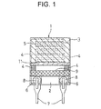
- FIG. 1 there is illustrated in plan view one exemplary arrangement of the humidity sensor device.
- the humidity sensor 1 includes a pair of interdigital or comb-shaped electrodes 4 on an insulating substrate 2.
- the pair of comb-shaped electrodes 4 are disposed on the substrate 2 and interdigitated with each other to define a gap 5 of a certain distance therebetween.
- the gap typically has a distance of about 100 to 500 ⁇ m.
- An undercoat layer 11 is formed over the insulating substrate 2 and comb-shaped electrodes 4, and a humidity sensitive thin film 3 is formed thereon.
- the comb-shaped electrodes 4 are provided at one end with electrode tabs 6 to which leads 7 are connected with solder welds 8.
- a resist film 9 is formed for preventing diffusion of the electrode material.
- voltage preferably AC voltage is applied across the electrodes 4. Since the humidity sensitive thin film 3 changes its electrical resistance or impedance in accordance with the humidity, the output voltage changes therewith, in terms of which the humidity is detectable.
- the applied voltage is typically up to about 12 volts.
- the insulating substrate 2 used herein may be formed of any desired material which is electrically insulating and well receptive to the electrodes 4 and undercoat layer 11.
- Useful substrates are glass, plastics, ceramics and metals coated with insulating material.
- the electrodes 4 may be made of any conventional electrode material. For example, they are formed by screen printing low resistance paste containing Au or RuO 2 and optionally glass frit, followed by high temperature firing.
- the electrode tabs 6 may be made of any conventional material which is compatible with the solder 8. For example, Ag-Pd alloy is printed in a conventional manner and baked at high temperatures to form the electrode tabs 6 Where gold is used as the electrodes 4, it is preferred that the resist film 9 of resist or glass is further provided in order to prevent diffusion of Au during soldering. No limits are imposed on the thickness and configuration of the resist film 9 as long as it is effective for preventing diffusion of Au during soldering.
- the humidity sensor of the present invention is not limited to the illustrated embodiment. Any desired shape or arrangement may be employed.
- the reaction solution was added dropwise to a large volume of acetone whereupon the polymer precipitated.
- the precipitate was collected by filtration and then dried in vacuum. After precipitation and purification of the polymer in this way, a 2-ethoxymethanol solution containing 5% by weight of the polymer was prepared.
- 0.02% by weight of Irgacure 184 commercially available from Ciba Specialty Chemicals was added as a polymerization initiator to complete a coating solution. Note that the polymer had Mn of about 5,000 prior to crosslinking.
- a humidity sensor 1 as shown in FIG. 1 was fabricated.
- a porous ceramic substrate of alumina was used as the insulating substrate 2.
- Comb-shaped electrodes 4 were formed on the substrate by screen printing paste containing RuO 2 and glass frit and firing at high temperature.
- the interdigital electrodes defined a gap of about 225 ⁇ m wide therebetween.
- the coating solution was coated onto the undercoat layer 11 on the insulating substrate 2 by dispensing an aliquot of 1.5 ⁇ l and then dried at room temperature for 30 minutes, forming a polymer coating.
- the coatings on the electrode-bearing surface and the rear surface of the substrate were exposed to ultraviolet radiation for 5 minutes on each surface, causing the polymer to crosslink.
- the dose of ultraviolet radiation was 25,000 mJ/cm 2 .
- the resulting humidity sensitive thin film 3 had a thickness of 3 ⁇ m.
- the humidity sensor thus fabricated was evaluated for output and examined by a water resistance test.
- a divided flow humidity generating machine model SRH-1 (manufactured by Shinei K.K.) was used.
- the humidity sensor was incorporated in the circuit described and shown in JP-A 2-123843.
- the humidity sensor incorporated in the circuit was set in the humidity generating machine where the relative humidity was changed stepwise from a low level to a high level and then from the high level to the low level both at 25°C.
- the humidity sensor which was allowed to stand at a selected relative humidity for 10 minutes was measured for output voltage.
- the selected relative humidity levels were RH 0%, RH 10%, RH 20%, RH 30%, RH 50%, RH 70%, and RH 90%. The results are plotted in FIG. 2.
- the humidity sensor having undergone humidity cycling for output voltage monitoring as mentioned above was immersed in distilled water for 1 minute, dried in air, and measured for output voltage again, which was compared with the initial output voltage (prior to water immersion).
- the time duration when the humidity sensor was immersed in distilled water was prolonged to 10 minutes, 30 minutes and 60 minutes whereupon the output voltage was similarly measured. The results are plotted in FIG. 3.
- the inventive humidity sensor exhibits no hysteresis and is able to measure low humidity, especially in a region of RH 10% or lower. It is evident from FIG. 3 that the inventive humidity sensor is fully resistant to water. The advantages of the present invention are thus demonstrated.
- Example 1 The resulting polymer was precipitated and purified. Except that this polymer was used as a conductive component, a humidity sensor was fabricated as in Example 1 by preparing a coating solution of the polymer and coating it to form a humidity sensitive thin film. Note that the polymer had Mn of about 110,000 prior to crosslinking.
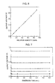
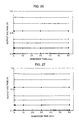
- FIG. 4 shows plots of output voltage versus relative humidity
- FIG. 5 shows the results of the water resistance test. The advantages of the present invention are evident from FIGS. 4 and 5.
- Example 1 a humidity sensor was fabricated as in Example 1 by preparing a coating solution of the polymer and coating it to form a humidity sensitive thin film. Note that the polymer had Mn of about 90,000 prior to crosslinking.
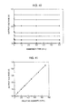
- FIG. 6 shows plots of output voltage versus relative humidity
- FIG. 7 shows the results of the water resistance test. The advantages of the present invention are evident from FIGS. 6 and 7.
- Example 1 Except that this polymer was used as a conductive component, a humidity sensor was fabricated as in Example 1 by preparing a coating solution of the polymer and coating it to form a humidity sensitive thin film. Note that the polymer had Mn of about 80,000 prior to crosslinking.
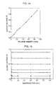
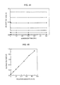
- FIG. 8 shows plots output voltage versus relative humidity
- FIG. 9 shows the results of the water resistance test. The advantages of the present invention are evident from FIGS. 8 and 9.
- Example 1 The resulting polymer was precipitated and purified. Except that this polymer was used as a conductive component, a humidity sensor was fabricated as in Example 1 by preparing a coating solution of the polymer and coating it to form a humidity sensitive thin film. Note that the polymer had Mn of about 80,000 prior to crosslinking.
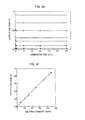
- FIG. 10 shows plots of output voltage versus relative humidity
- FIG. 11 shows the results of the water resistance test. The advantages of the present invention are evident from FIGS 10 and 11.
- Example 1 Except that this polymer was used as a conductive component, a humidity sensor was fabricated as in Example 1 by preparing a coating solution of the polymer and coating it to form a humidity sensitive thin film. Note that the polymer had Mn of about 100,000 prior to crosslinking.
- FIG. 12 shows plots of output voltage versus relative humidity
- FIG. 13 shows the results of the water resistance test. The advantages of the present invention are evident from FIGS. 12 and 13.
- Example 1 a humidity sensor was fabricated as in Example 1 by preparing a coating solution of the polymer and coating it to form a humidity sensitive thin film. Note that the polymer had Mn of about 80,000 prior to crosslinking.
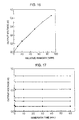
- FIG. 14 shows plots of output voltage versus relative humidity
- FIG. 15 shows the results of the water resistance test. The advantages of the present invention are evident from FIGS. 14 and 15.
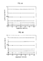
- FIG. 16 shows plots of output voltage versus relative humidity
- FIG. 17 shows the results of the water resistance test. The advantages of the present invention are evident from FIGS. 16 and 17.
- Example 1 The resulting polymer was precipitated and purified. Except that this polymer was used as a conductive component, a humidity sensor was fabricated as in Example 1 by preparing a coating solution of the polymer and coating it to form a humidity sensitive thin film. Note that the polymer had Mn of about 150,000 prior to crosslinking.
- the humidity sensor was evaluated for output and examined by the water resistance test as in Example 1.
- FIG. 18 shows plots of output voltage versus relative humidity and
- FIG. 19 shows the results of the water resistance test. It is seen from FIG. 18 that this sensor enabled humidity measurement over a relatively wide region although measurement was impossible in the region of RH 0% through 10% because the dibromo compound was used as the dihalogen compound.
- the sensor had improved water resistance as seen from FIG. 19.
- Example 1 The resulting polymer was precipitated and purified. Except that this polymer was used as a conductive component, a humidity sensor was fabricated as in Example 1 by preparing a coating solution of the polymer and coating it to form a humidity sensitive thin film. Note that the polymer had Mn of about 130,000 prior to crosslinking.
- FIG. 20 shows plots of output voltage versus relative humidity and FIG. 21 shows the results of the water resistance test.
- FIGS. 20 and 21 show that the results are the same as in Example 9.
- Example 1 A humidity sensor was fabricated as in Example 1 and similarly evaluated for output and water resistance. The results were equivalent to those of Example 1.
- FIG. 22 shows plots of output voltage versus relative humidity and FIG. 23 shows the results of the water resistance test. The advantages of the present invention are evident from FIGS. 22 and 23.
- a humidity sensor was fabricated as in Example 1 except that in introducing a reactive group into the intermediate polymer at its end, the reaction solution was stirred for 20 hours at the reflux temperature instead of stirring for 100 hours at 35°C. Note that the polymer had Mn of about 130,000 prior to crosslinking.
- Example 1 The humidity sensor was evaluated for output and examined by the water resistance test as in Example 1.
- the output voltage versus relative humidity was the same as in Example 1.
- FIG. 24 shows the results of the water resistance test.
- the water resistance of the sensor of this Example was better than that of Example 1 since the reactive group was introduced into the intermediate polymer at a higher temperature than in Example 1 whereby some reactive groups underwent polymerization.
- a humidity sensor was fabricated as in Example 2 except that in introducing a reactive group into the intermediate polymer at its end, the reaction solution was stirred for 25 hours at 80°C instead of stirring for 120 hours at 45°C. Note that the polymer had Mn of about 90,000 prior to crosslinking.
- Example 1 The humidity sensor was evaluated for output and examined by the water resistance test as in Example 1.
- the output voltage versus relative humidity was the same as in Example 2.
- FIG. 25 shows the results of the water resistance test.
- the water resistance of the sensor of this Example was better than that of Example 2 since the reactive group was introduced into the intermediate polymer at a higher temperature than in Example 2 whereby some reactive groups underwent polymerization.
- a humidity sensor was fabricated as in Example 3 except that in introducing a reactive group into the intermediate polymer at its end, the reaction solution was stirred for 20 hours at 80°C instead of stirring for 120 hours at 45°C. Note that the polymer had Mn of about 80,000 prior to crosslinking.
- Example 1 The humidity sensor was evaluated for output and examined by the water resistance test as in Example 1.
- the output voltage versus relative humidity was the same as in Example 3.
- FIG. 26 shows the results of the water resistance test.
- the water resistance of the sensor of this Example was better than that of Example 3 since the reactive group was introduced into the intermediate polymer at a higher temperature than in Example 3 whereby some reactive groups underwent polymerization.
- a humidity sensor was fabricated as in Example 5 except that in introducing a reactive group into the intermediate polymer at its end, the reaction solution was stirred for 20 hours at 80° C instead of stirring for 120 hours at 45°C. Note that the polymer had Mn of about 80,000 prior to crosslinking.
- Example 1 The humidity sensor was evaluated for output and examined by the water resistance test as in Example 1.
- the output voltage versus relative humidity was the same as in Example 5.
- FIG. 27 shows the results of the water resistance test.
- the water resistance of the sensor of this Example was better than that of Example 5 since the reactive group was introduced into the intermediate polymer at a higher temperature than in Example 5 whereby some reactive groups underwent polymerization.
- a humidity sensor was fabricated as in Example 6 except that in introducing a reactive group into the intermediate polymer at its end, the reaction solution was stirred for 20 hours at 80°C instead of stirring for 120 hours at 45°C. Note that the polymer had Mn of about 80,000 prior to crosslinking.
- Example 1 The humidity sensor was evaluated for output and examined by the water resistance test as in Example 1.
- the output voltage versus relative humidity was the same as in Example 6.
- FIG. 28 shows the results of the water resistance test.
- the water resistance of the sensor of this Example was better than that of Example 6 since the reactive group was introduced into the intermediate polymer at a higher temperature than in Example 6 whereby some reactive groups underwent polymerization.
- a humidity sensor was fabricated as in Example 7 except that in introducing a reactive group into the intermediate polymer at its end, the reaction solution was stirred for 20 hours at 80°C instead of stirring for 120 hours at 45°C. Note that the polymer had Mn of about 100,000 prior to crosslinking.
- Example 7 The humidity sensor was evaluated for output and examined by the water resistance test as in Example 1.
- the output voltage versus relative humidity was the same as in Example 7.
- FIG. 29 shows the results of the water resistance test.
- the water resistance of the sensor of this Example was better than that of Example 7 since the reactive group was introduced into the intermediate polymer at a higher temperature than in Example 7 whereby some reactive groups underwent polymerization.
- a humidity sensor was fabricated as in Example 8 except that in introducing a reactive group into the intermediate polymer at its end, the reaction solution was stirred for 20 hours at 80° C instead of stirring for 100 hours at 35°C. Note that the polymer had Mn of about 80,000 prior to crosslinking.
- Example 1 The humidity sensor was evaluated for output and examined by the water resistance test as in Example 1.
- the output voltage versus relative humidity was the same as in Example 8.
- FIG. 30 shows the results of the water resistance test.
- the water resistance of the sensor of this Example was better than that of Example 8 since the reactive group was introduced into the intermediate polymer at a higher temperature than in Example 8 whereby some reactive groups underwent polymerization.
- a humidity sensor was fabricated as in Example 10 except that in introducing a reactive group into the intermediate polymer at its end, the reaction solution was stirred for 20 hours at the reflux temperature instead of stirring for 100 hours at 35°C. Note that the polymer had Mn of about 150,000 prior to crosslinking.
- Example 1 The humidity sensor was evaluated for output and examined by the water resistance test as in Example 1.
- the output voltage versus relative humidity was the same as in Example 10.
- FIG. 31 shows the results of the water resistance test.
- the water resistance of the sensor of this Example was better than that of Example 10 since the reactive group was introduced into the intermediate polymer at a higher temperature than in Example 10 whereby some reactive groups underwent polymerization.
- a humidity sensor was fabricated as in Example 11 except that in introducing a reactive group into the intermediate polymer at its end, the reaction solution was stirred for 20 hours at 80°C instead of stirring for 100 hours at 35°C. Note that the polymer had Mn of about 150,000 prior to crosslinking.
- Example 1 The humidity sensor was evaluated for output and examined by the water resistance test as in Example 1.
- the output voltage versus relative humidity was the same as in Example 11.
- FIG. 32 shows the results of the water resistance test.
- the water resistance of the sensor of this Example was better than that of Example 11 since the reactive group was introduced into the intermediate polymer at a higher temperature than in Example 11 whereby some reactive groups underwent polymerization.
- reaction solution was cooled, to which 30 g of 2-propanol was added.
- the reaction solution was added dropwise to a large volume of acetone whereupon an intermediate polymer precipitated.
- the precipitate was collected by filtration through a glass filter and dried in vacuum.
- Example 1 Except that this polymer was used as a conductive component, a humidity sensor was fabricated as in Example 1 by preparing a coating solution of the polymer and coating it to form a humidity sensitive thin film. Note that the polymer had Mn of about 130,000 prior to crosslinking.
- FIG. 33 shows plots of output voltage versus relative humidity and FIG. 34 shows the results of the water resistance test. The advantages of the present invention are evident from FIGS. 33 and 34.
- reaction solution was cooled, to which 30 g of 2-propanol was added.
- the reaction solution was added dropwise to a large volume of acetone whereupon an intermediate polymer precipitated.
- the precipitate was collected by filtration through a glass filter and dried in vacuum.
- Example 1 Except that this polymer was used as a conductive component, a humidity sensor was fabricated as in Example 1 by preparing a coating solution of the polymer and coating it to form a humidity sensitive thin film. Note that the polymer had Mn of about 110,000 prior to crosslinking.
- FIG. 35 shows plots of output voltage versus relative humidity
- FIG. 36 shows the results of the water resistance test. The advantages of the present invention are evident from FIGS. 35 and 36.
- reaction solution was cooled, to which 30 g of 2-propanol was added.
- the reaction solution was added dropwise to a large volume of acetone whereupon an intermediate polymer precipitated.
- the precipitate was collected by filtration through a glass filter and dried in vacuum.
- Example 1 Except that this polymer was used as a conductive component, a humidity sensor was fabricated as in Example 1 by preparing a coating solution of the polymer and coating it to form a humidity sensitive thin film. Note that the polymer had Mn of about 120,000 prior to crosslinking.
- FIG. 37 shows plots of output voltage versus relative humidity and FIG. 38 shows the results of the water resistance test. The advantages of the present invention are evident from FIGS. 37 and 38.
- reaction solution was stirred for a further 25 hours at the reflux temperature. At the end of reaction, the reaction solution was cooled, to which 30 g of 2-propanol was added. The reaction solution was added dropwise to a large volume of acetone whereupon an intermediate polymer precipitated. The precipitate was collected by filtration through a glass filter and dried in vacuum.
- Example 1 Except that this polymer was used as a conductive component, a humidity sensor was fabricated as in Example 1 by preparing a coating solution of the polymer and coating it to form a humidity sensitive thin film. Note that the polymer had Mn of about 90,000 prior to crosslinking.
- FIG. 39 shows plots of output voltage versus relative humidity
- FIG. 40 shows the results of the water resistance test. The advantages of the present invention are evident from FIGS. 39 and 40.
- Example 1 Except that this polymer was used as a conductive component, a humidity sensor was fabricated as in Example 1 by preparing a coating solution of the polymer and coating it to form a humidity sensitive thin film. Note that the polymer had Mn of about 50,000 prior to crosslinking.
- FIG. 41 shows plots of output voltage versus relative humidity and FIG. 42 shows the results of the water resistance test. The advantages of the present invention are evident from FIGS. 41 and 42.
- reaction solution was cooled, to which 30 g of 2-propanol was added.
- the reaction solution was added dropwise to a large volume of acetone whereupon an intermediate polymer precipitated.
- the precipitate was collected by filtration through a glass filter and dried in vacuum (yield 16.2 g).
- Example 1 Except that this polymer was used as a conductive component, a humidity sensor was fabricated as in Example 1 by preparing a coating solution of the polymer and coating it to form a humidity sensitive thin film. Note that the polymer had Mn of about 60,000 prior to crosslinking.
- FIG. 43 shows plots of output voltage versus relative humidity and FIG. 44 shows the results of the water resistance test. The advantages of the present invention are evident from FIGS. 43 and 44.
- reaction solution was cooled, to which 30 g of 2-propanol was added.
- the reaction solution was added dropwise to a large volume of acetone whereupon an intermediate polymer precipitated.
- the precipitate was collected by filtration through a glass filter and dried in vacuum (yield 15.2 g).
- Example 1 Except that this polymer was used as a conductive component, a humidity sensor was fabricated as in Example 1 by preparing a coating solution of the polymer and coating it to form a humidity sensitive thin film. Note that the polymer had Mn of about 40,000 prior to crosslinking.
- FIG. 45 shows plots of output voltage versus relative humidity
- FIG. 46 shows the results of the water resistance test. The advantages of the present invention are evident from FIGS. 45 and 46.
- Example 1 Except that this polymer was used as a conductive component, a humidity sensor was fabricated as in Example 1 by preparing a coating solution of the polymer and coating it to form a humidity sensitive thin film. Note that the polymer had Mn of about 50,000 prior to crosslinking.
- FIG. 47 shows plots of output voltage versus relative humidity and FIG. 48 shows the results of the water resistance test. The advantages of the present invention are evident from FIGS. 47 and 48.
- Example 29 The intermediate polymer synthesized, separated and purified in Example 29, 15.0 g, and 15.0 g of N-(3-dimethylaminopropyl)acrylamide were dissolved in 30.0 g of methanol. The solution was stirred at 25°C for 24 hours, introducing a reactive group into the intermediate polymer at its end. At the end of reaction, 30 g of 2-propanol was added to the reaction solution, which was added dropwise to a large volume of acetone whereupon the polymer precipitated. The precipitate was collected by filtration through a glass filter and then dried in vacuum (yield 16.2 g).
- Example 1 Except that this polymer was used as a conductive component, a humidity sensor was fabricated as in Example 1 by preparing a coating solution of the polymer and coating it to form a humidity sensitive thin film. Note that the polymer had Mn of about 50,000 prior to crosslinking.
- the humidity sensor was evaluated for output and examined by the water resistance test as in Example 1.
- the output voltage versus relative humidity was the same as in Example 29.
- FIG. 49 shows the results of the water resistance test. The advantages of the present invention are evident from these results.
- Example 1 Except that this polymer was used as a conductive component, a humidity sensor was fabricated as in Example 1 by preparing a coating solution of the polymer and coating it to form a humidity sensitive thin film. Note that the polymer had Mn of about 40,000 prior to crosslinking.
- FIG. 50 shows plots of output voltage versus relative humidity
- FIG. 51 shows the results of the water resistance test. The advantages of the present invention are evident from FIGS. 50 and 51.
- Example 1 Except that this polymer was used as a conductive component, a humidity sensor was fabricated as in Example 1 by preparing a coating solution of the polymer and coating it to form a humidity sensitive thin film. Note that the polymer had Mn of about 50,000 prior to crosslinking.
- FIG. 52 shows plots of output voltage versus relative humidity
- FIG. 53 shows the results of the water resistance test. The advantages of the present invention are evident from FIGS. 52 and 53.
- Example 1 Except that this polymer was used as a conductive component, a humidity sensor was fabricated as in Example 1 by preparing a coating solution of the polymer and coating it to form a humidity sensitive thin film. Note that the polymer had Mn of about 70,000 prior to crosslinking.
- FIG. 54 shows plots of output voltage versus relative humidity and FIG. 55 shows the results of the water resistance test. The advantages of the present invention are evident from FIGS. 54 and 55.
- Example 1 Except that this polymer was used as a conductive component, a humidity sensor was fabricated as in Example 1 by preparing a coating solution of the polymer and coating it to form a humidity sensitive thin film. Note that the polymer had Mn of about 70,000 prior to crosslinking.
- FIG. 56 shows plots of output voltage versus relative humidity
- FIG. 57 shows the results of the water resistance test. The advantages of the present invention are evident from FIGS. 56 and 57.
- Example 34 The intermediate polymer synthesized, separated and purified in Example 34, 15.0 g, and 15.0 g of N-(3-dimethylaminopropyl)acrylamide were dissolved in 30.0 g of methanol. The solution was stirred at 25°C for 24 hours, introducing a reactive group into the intermediate polymer at its end. At the end of reaction, 30 g of 2-propanol was added to the reaction solution, which was added dropwise to a large volume of acetone whereupon the polymer precipitated. The precipitate was collected by filtration through a glass filter and then dried in vacuum (yield 15.1 g).
- Example 1 Except that this polymer was used as a conductive component, a humidity sensor was fabricated as in Example 1 by preparing a coating solution of the polymer and coating it to form a humidity sensitive thin film. Note that the polymer had Mn of about 70,000 prior to crosslinking.
- the humidity sensor was evaluated for output and examined by the water resistance test as in Example 1.
- the output voltage versus relative humidity was the same as in Example 34.
- FIG. 58 shows the results of the water resistance test. The advantages of the present invention are evident from these results.
- reaction solution was cooled, to which 30 g of 2-propanol was added.
- the resulting solution was added dropwise to a large volume of acetone whereupon an intermediate polymer precipitated.
- the precipitate was collected by filtration through a glass filter and dried in vacuum (yield 17.5 g).
- Example 1 Except that this polymer was used as a conductive component, a humidity sensor was fabricated as in Example 1 by preparing a coating solution of the polymer and coating it to form a humidity sensitive thin film. Note that the polymer had Mn of about 50,000 prior to crosslinking.
- FIG. 59 shows plots of output voltage versus relative humidity and FIG. 60 shows the results of the water resistance test. The advantages of the present invention are evident from FIGS. 59 and 60.
- Example 36 The intermediate polymer synthesized, separated and purified in Example 36, 15.0 g, and 15.0 g of N-(3-dimethylaminopropyl)acrylamide were dissolved in 30.0 g of methanol. The solution was stirred at 25°C for 24 hours, introducing a reactive group into the intermediate polymer at its end. At the end of reaction, 30 g of 2-propanol was added to the reaction solution, which was added dropwise to a large volume of acetone whereupon the polymer precipitated. The precipitate was collected by filtration through a glass filter and then dried in vacuum (yield 18.2 g).
- Example 1 Except that this polymer was used as a conductive component, a humidity sensor was fabricated as in Example 1 by preparing a coating solution of the polymer and coating it to form a humidity sensitive thin film. Note that the polymer had Mn of about 50,000 prior to crosslinking.
- the humidity sensor was evaluated for output and examined by the water resistance test as in Example 1.
- the output voltage versus relative humidity was the same as in Example 36.
- FIG. 61 shows the results of the water resistance test. The advantages of the present invention are evident from these results.
- reaction solution was cooled and 30 g of 2-propanol was added thereto.
- the solution was added dropwise to a large volume of acetone whereupon an intermediate polymer precipitated.
- the precipitate was collected by filtration through a glass filter and dried in vacuum (yield 15.5 g).
- Example 1 Except that this polymer was used as a conductive component, a humidity sensor was fabricated as in Example 1 by preparing a coating solution of the polymer and coating it to form a humidity sensitive thin film. Note that the polymer had Mn of about 60,000 prior to crosslinking.
- FIG. 62 shows plots of output voltage versus relative humidity and FIG. 63 shows the results of the water resistance test. The advantages of the present invention are evident from FIGS. 62 and 63.
- reaction solution was cooled and 30 g of 2-propanol was added thereto.
- the solution was added dropwise to a large volume of acetone whereupon an intermediate polymer precipitated.
- the precipitate was collected by filtration through a glass filter and dried in vacuum (yield 16.5 g).
- Example 1 Except that this polymer was used as a conductive component, a humidity sensor was fabricated as in Example 1 by preparing a coating solution of the polymer and coating it to form a humidity sensitive thin film. Note that the polymer had Mn of about 50,000 prior to crosslinking.
- FIG. 64 shows plots of output voltage versus relative humidity
- FIG. 65 shows the results of the water resistance test. The advantages of the present invention are evident from FIGS. 64 and 65.
- Example 39 The intermediate polymer synthesized, separated and purified in Example 39, 15.0 g, and 15.0 g of N-(3-dimethylaminopropyl)acrylamide were dissolved in 30.0 g of methanol. The solution was stirred at 25°C for 24 hours, introducing a reactive group into the intermediate polymer at its end. At the end of reaction, 30 g of 2-propanol was added to the reaction solution, which was added dropwise to a large volume of acetone whereupon the polymer precipitated. The precipitate was collected by filtration through a glass filter and then dried in vacuum (yield 17.9 g).
- Example 1 Except that this polymer was used as a conductive component, a humidity sensor was fabricated as in Example 1 by preparing a coating solution of the polymer and coating it to form a humidity sensitive thin film. Note that the polymer had Mn of about 60,000 prior to crosslinking.
- the humidity sensor was evaluated for output and examined by the water resistance test as in Example 1.
- the output voltage versus relative humidity was the same as in Example 39.
- FIG. 66 shows the results of the water resistance test. The advantages of the present invention are evident from these results.
- Humidity sensitive thin films were prepared and humidity sensors were fabricated as in Examples 1-7, 9-11, and 13-40 except that a diamine compound and a dihalogen compound both other than the above-mentioned ones were used in different combinations, the amounts of these compounds added were changed in accordance with the first reaction scheme (Example 1) and the second reaction scheme (Example 13), and a compound having an ethylenically unsaturated reactive group was changed.
- humidity sensitive thin films were prepared and humidity sensors were fabricated as in Example 1. These humidity sensors were similarly tested for output and water resistance, finding that results equivalent to those of Examples 1-40 were obtained depending on the particular diamine and dihalogen compounds and reaction conditions used.
- a humidity sensor was fabricated in accordance with JP-B 62-7976 and examined for output as in Example 1.
- FIG. 67 shows plots of output voltage versus relative humidity.
- the humidity sensitive material used herein was poly(2-hydroxy-3-methacryloxypropyltrimethylammonium chloride) of the following formula.
- a humidity sensitive thin film was formed by coating a solution of this polymer to an electrode-bearing substrate, applying an ammonium bichromate solution to the coating, baking the coating, irradiating ultraviolet radiation for 2 or 3 minutes for crosslinking.
- the sensor of Example 1 in USP 5,546,802 was tested for output before and after exposure to chlorine gas.
- the gas exposure was by holding the sensor for 96 hours in an atmosphere having a Cl 2 gas concentration of 1 ppm, a temperature of 40°C and a relative humidity (RH) of 70-80%.
- the sensor of the present Example 1 was tested under the same conditions. The results are shown in FIG. 68. It is evident that the output of the inventive sensor remains unchanged before and after exposure to chlorine gas.
- Example 1 in USP 5,546,802 was tested for output before and after exposure to nitrogen dioxide gas.
- the gas exposure was by holding the sensor for 96 hours in an atmosphere having a NO 2 gas concentration of 1 ppm, a temperature of 40°C and RH 70-80%.
- the sensor of the present Example 1 was tested under the same conditions. The results are shown in FIG. 69. It is evident that the output of the inventive sensor remains unchanged before and after exposure to NO 2 gas.
- the sensor of Example 1 in USP 5,546,802 was tested for output before and after exposure to sulfur dioxide gas.
- the gas exposure was by holding the sensor for 96 hours in an atmosphere having a SO 2 gas concentration of 5 ppm, a temperature of 40° C and RH 70-80%.
- the sensor of the present Example 1 was tested under the same conditions. The results are shown in FIG. 70. It is evident that the output of the inventive sensor remains unchanged before and after exposure to SO 2 gas.
- Example 1 A humidity sensor was fabricated as in Example 1 except that the coating solution of the polymer in Example 1 was applied directly to the substrate without the intervening layer of KBM1003. A water resistance test was conducted on this sensor as in Example 1.
- FIG. 71 shows the results of the water resistance test. It is seen from FIG. 71 that absent the silane compound layer, the humidity sensitive film swelled and stripped during the water resistance test, indicating poor water resistance.
- Humidity sensors were fabricated as in Example 1 except that in the step of applying the coating solution of the polymer by dispensing, the amount of the solution dispensed was changed to 0.5 ⁇ l, 0.75 ⁇ l, 1.0 ⁇ l, 1.25 ⁇ l and 1.50 ⁇ l, thereby changing the thickness of the humidity sensitive film to 1.2 ⁇ m, 1.8 ⁇ m, 2.3 ⁇ m, 2.9 ⁇ m and 3.2 ⁇ m, respectively.
- these sensors were tested for output before and after exposure to chlorine, nitrogen dioxide and sulfur dioxide gases, from which output changes by gas exposure were computed. The results are shown in Table 1.
Landscapes
- Chemical & Material Sciences (AREA)
- Chemical Kinetics & Catalysis (AREA)
- Electrochemistry (AREA)
- Physics & Mathematics (AREA)
- Health & Medical Sciences (AREA)
- Life Sciences & Earth Sciences (AREA)
- Analytical Chemistry (AREA)
- Biochemistry (AREA)
- General Health & Medical Sciences (AREA)
- General Physics & Mathematics (AREA)
- Immunology (AREA)
- Pathology (AREA)
- Investigating Or Analyzing Materials By The Use Of Fluid Adsorption Or Reactions (AREA)
Applications Claiming Priority (2)
| Application Number | Priority Date | Filing Date | Title |
|---|---|---|---|
| JP2000098643 | 2000-03-31 | ||
| JP2000098643 | 2000-03-31 |
Publications (2)
| Publication Number | Publication Date |
|---|---|
| EP1139092A2 true EP1139092A2 (de) | 2001-10-04 |
| EP1139092A3 EP1139092A3 (de) | 2004-03-10 |
Family
ID=18613102
Family Applications (1)
| Application Number | Title | Priority Date | Filing Date |
|---|---|---|---|
| EP01302919A Ceased EP1139092A3 (de) | 2000-03-31 | 2001-03-28 | Feuchtigkeitssensor und dessen Verfahren zur Herstellung |
Country Status (5)
| Country | Link |
|---|---|
| US (1) | US6568265B2 (de) |
| EP (1) | EP1139092A3 (de) |
| KR (1) | KR100429249B1 (de) |
| CN (1) | CN1235043C (de) |
| TW (1) | TW507073B (de) |
Cited By (3)
| Publication number | Priority date | Publication date | Assignee | Title |
|---|---|---|---|---|
| CN100385703C (zh) * | 2005-01-18 | 2008-04-30 | 黄德欢 | 含硅共聚物电阻型薄膜湿敏元件及其制作方法 |
| EP2009432A1 (de) * | 2007-06-27 | 2008-12-31 | Valtion Teknillinen Tutkimuskeskus | Zeit- und Feuchtesensor und dessen Verwendung |
| CN106896141A (zh) * | 2017-03-22 | 2017-06-27 | 吉林大学 | 一种基于可溶液加工聚合物修饰二氧化硅粒子的阻抗型湿敏元件及其制备方法 |
Families Citing this family (25)
| Publication number | Priority date | Publication date | Assignee | Title |
|---|---|---|---|---|
| KR100570586B1 (ko) * | 2002-12-17 | 2006-04-13 | (주)아이블포토닉스 | 강유전성 단결정 막 구조물 제조 방법 |
| US7282261B2 (en) * | 2003-02-13 | 2007-10-16 | National University Of Singapore | Method of enhancing the stability of electroactive polymers and redox active materials |
| CN100359323C (zh) * | 2003-04-25 | 2008-01-02 | 乐金电子(天津)电器有限公司 | 微波炉用湿度传感器 |
| KR100539392B1 (ko) * | 2003-08-12 | 2005-12-27 | (주)해은켐텍 | 습도센서 감습막용 전해질 고분자 조성물, 그로부터제조되는 전해질 고분자 잉크 및 잉크젯 인쇄방식을이용하여 감습막을 형성하는 습도센서 제조방법 |
| KR100680311B1 (ko) * | 2004-12-29 | 2007-02-08 | 이정록 | 수분 감지용 센서의 제조방법 |
| CN1300575C (zh) * | 2004-12-29 | 2007-02-14 | 浙江大学 | 具有互穿网络结构的高分子电阻型薄膜湿敏元件及其制作方法 |
| CN100357039C (zh) * | 2005-03-23 | 2007-12-26 | 北京青鸟元芯微系统科技有限责任公司 | 平面式气体传感器衬底上敏感材料的涂覆方法 |
| TWI289202B (en) * | 2005-12-15 | 2007-11-01 | Forward Electronics Co Ltd | Humidity sensor and its fabricating method |
| JP4732902B2 (ja) * | 2006-01-18 | 2011-07-27 | セイコーインスツル株式会社 | 湿度センサおよびそれを有する半導体装置 |
| TWI314989B (en) * | 2006-06-23 | 2009-09-21 | Fego Prec Ind Co Ltd | Humidity sensor having temperature compensation self-comparing and manufacturing method therefore |
| CN100439910C (zh) * | 2006-09-29 | 2008-12-03 | 浙江大学 | 高耐水特性的高分子电阻型薄膜湿敏元件及其制作方法 |
| DE102007011544B3 (de) * | 2007-03-09 | 2008-06-05 | Dräger Medical AG & Co. KG | Verfahren zur Regelung eines Beatmungsanfeuchters sowie zugeordnete Vorrichtung |
| US20100307238A1 (en) * | 2009-06-05 | 2010-12-09 | The Governors Of The University Of Alberta | Humidity sensor and method of manufacturing the same |
| CN102565146B (zh) * | 2011-12-27 | 2014-06-04 | 郑州炜盛电子科技有限公司 | 电阻型湿敏元件及其制备方法 |
| CN103969294B (zh) * | 2013-01-25 | 2016-06-01 | 泰科电子(上海)有限公司 | 硅油检测器、电力终端组件和硅油检测器的使用方法 |
| US10787551B2 (en) * | 2013-02-28 | 2020-09-29 | Cornell University | Cross-linked polymer networks and methods of making and using same |
| US9568445B2 (en) * | 2014-04-09 | 2017-02-14 | International Business Machines Corporation | Salt-based device and a circuit to monitor and log the times a data center air goes above a predefined limit |
| EP2985233B1 (de) * | 2014-08-12 | 2017-03-22 | Sunbeam Products, Inc. | Nahrungsmittellagerungsvorrichtung mit feuchtigkeitssensor |
| CN104914138A (zh) * | 2015-07-03 | 2015-09-16 | 深圳市共进电子股份有限公司 | 湿度传感器、湿度传感器阵列及其制备方法 |
| CN105928995B (zh) * | 2016-05-31 | 2018-04-03 | 苏州大学 | 一种基于方酸菁聚合物的湿敏传感器及其制备方法和用途 |
| CN209326840U (zh) | 2018-12-27 | 2019-08-30 | 热敏碟公司 | 压力传感器及压力变送器 |
| CN109939875B (zh) * | 2019-03-11 | 2021-01-05 | 哈尔滨工业大学(深圳) | 一种声表面波雾化芯片、制作方法及装置 |
| CN112345600B (zh) * | 2020-10-21 | 2022-03-11 | 东南大学 | 一种基于疏水聚四氟乙烯微孔材料包覆的柔性湿度传感器的制备工艺 |
| CN115290709B (zh) * | 2022-08-05 | 2024-10-29 | 郑州炜盛电子科技有限公司 | 基于交联型有机季铵盐的电阻式湿度传感器及其制备方法 |
| CN117621591B (zh) * | 2023-11-17 | 2026-03-20 | 北京科技大学 | 一种兼具调湿和抗菌能力的智能复合薄膜、制备方法及应用 |
Family Cites Families (12)
| Publication number | Priority date | Publication date | Assignee | Title |
|---|---|---|---|---|
| JPS58176538A (ja) * | 1982-04-09 | 1983-10-17 | Sharp Corp | 感湿抵抗素子 |
| JPS58216945A (ja) * | 1982-06-11 | 1983-12-16 | Mitsubishi Electric Corp | 湿度センサ |
| JPS6154176A (ja) | 1984-08-24 | 1986-03-18 | 松下電工株式会社 | ヒ−タ断線検出回路 |
| JPS627976A (ja) | 1985-07-02 | 1987-01-14 | Honda Motor Co Ltd | 内燃エンジンの点火時期制御方法 |
| DE3751502T2 (de) * | 1986-03-11 | 1996-02-15 | Kanegafuchi Chemical Ind | Elektrische oder elektronische Anordnung mit einer dünnen Schicht aus Polyimid. |
| JPH0718832B2 (ja) * | 1986-04-19 | 1995-03-06 | 神栄株式会社 | 感湿素子 |
| FR2644829B2 (fr) | 1988-04-15 | 1991-05-17 | Zivanovic Milovoje | Dispositif antivol pour portes de vehicules ou de conteneurs |
| JPH0786493B2 (ja) * | 1992-04-24 | 1995-09-20 | 松下電器産業株式会社 | 湿度センサー |
| JPH0718832A (ja) | 1993-06-29 | 1995-01-20 | Matsushita Electric Works Ltd | 木質床板 |
| DE69502985T2 (de) * | 1994-03-31 | 1999-02-25 | Tdk Corp., Tokio/Tokyo | Feuchtigkeitsfühler und Verfahren zur dessen Herstellung |
| JP2808255B2 (ja) | 1994-03-31 | 1998-10-08 | ティーディーケイ株式会社 | 湿度センサ素子 |
| JP3557245B2 (ja) * | 1994-05-24 | 2004-08-25 | 松下電器産業株式会社 | 感湿素子及びその製造方法 |
-
2001
- 2001-03-27 TW TW090107216A patent/TW507073B/zh not_active IP Right Cessation
- 2001-03-28 EP EP01302919A patent/EP1139092A3/de not_active Ceased
- 2001-03-30 CN CNB011178566A patent/CN1235043C/zh not_active Expired - Lifetime
- 2001-03-30 US US09/820,644 patent/US6568265B2/en not_active Expired - Lifetime
- 2001-03-30 KR KR10-2001-0016993A patent/KR100429249B1/ko not_active Expired - Lifetime
Cited By (4)
| Publication number | Priority date | Publication date | Assignee | Title |
|---|---|---|---|---|
| CN100385703C (zh) * | 2005-01-18 | 2008-04-30 | 黄德欢 | 含硅共聚物电阻型薄膜湿敏元件及其制作方法 |
| EP2009432A1 (de) * | 2007-06-27 | 2008-12-31 | Valtion Teknillinen Tutkimuskeskus | Zeit- und Feuchtesensor und dessen Verwendung |
| CN106896141A (zh) * | 2017-03-22 | 2017-06-27 | 吉林大学 | 一种基于可溶液加工聚合物修饰二氧化硅粒子的阻抗型湿敏元件及其制备方法 |
| CN106896141B (zh) * | 2017-03-22 | 2019-05-28 | 吉林大学 | 一种基于聚合物修饰二氧化硅粒子的湿敏元件及制备方法 |
Also Published As
| Publication number | Publication date |
|---|---|
| KR20010095179A (ko) | 2001-11-03 |
| EP1139092A3 (de) | 2004-03-10 |
| US6568265B2 (en) | 2003-05-27 |
| CN1235043C (zh) | 2006-01-04 |
| KR100429249B1 (ko) | 2004-04-29 |
| US20010037681A1 (en) | 2001-11-08 |
| TW507073B (en) | 2002-10-21 |
| CN1320817A (zh) | 2001-11-07 |
Similar Documents
| Publication | Publication Date | Title |
|---|---|---|
| US6568265B2 (en) | Humidity sensor and method for making | |
| US6615659B2 (en) | Humidity sensor and method for manufacturing the same | |
| EP0676636B1 (de) | Feuchtigkeitsfühler und Verfahren zur dessen Herstellung | |
| US4908117A (en) | Solid state reference electrode | |
| CA1199537A (en) | Humidity sensor and method for preparing the same | |
| AU599434B2 (en) | A solid state reference electrode | |
| JPH0548411B2 (de) | ||
| Lee et al. | Humidity‐sensitive properties of new polyelectrolytes based on the copolymers containing phosphonium salt and phosphine function | |
| Lee et al. | Resistive humidity sensor using phosphonium salt-containing polyelectrolytes based on the mutually cross-linkable copolymers | |
| JP2003262600A (ja) | 湿度センサ素子の製造方法と湿度センサ素子 | |
| JP2808255B2 (ja) | 湿度センサ素子 | |
| JP3967886B2 (ja) | 湿度センサ素子およびその製造方法 | |
| JP2004301766A (ja) | 感湿材用組成物、感湿材料および湿度センサ素子 | |
| JP3866991B2 (ja) | 湿度センサ素子およびその製造方法 | |
| Jeon et al. | Polymeric humidity sensor using polyelectrolyte derived from poly (amide-sulfone) s | |
| JP3557245B2 (ja) | 感湿素子及びその製造方法 | |
| Lee et al. | Humidity-sensitive properties of self-assembled polyelectrolyte system | |
| JP2001221764A (ja) | 湿度センサ素子およびその製造方法 | |
| JPS60113140A (ja) | 湿度センサ素子 | |
| JP2005291852A (ja) | 湿度センサ素子 | |
| Han et al. | New efficient polyelectrolyte containing zwitterionic sulfobetaine salt for the high sensitive resistive humidity sensor | |
| JPH06160327A (ja) | 湿度センサ素子およびその製造方法 | |
| JP2004354083A (ja) | 湿度センサ素子の製造方法 | |
| JP2969547B2 (ja) | 湿度センサおよびその製造方法 | |
| JP2005291880A (ja) | 湿度センサ素子 |
Legal Events
| Date | Code | Title | Description |
|---|---|---|---|
| PUAI | Public reference made under article 153(3) epc to a published international application that has entered the european phase |
Free format text: ORIGINAL CODE: 0009012 |
|
| AK | Designated contracting states |
Kind code of ref document: A2 Designated state(s): AT BE CH CY DE DK ES FI FR GB GR IE IT LI LU MC NL PT SE TR |
|
| AX | Request for extension of the european patent |
Free format text: AL;LT;LV;MK;RO;SI |
|
| PUAL | Search report despatched |
Free format text: ORIGINAL CODE: 0009013 |
|
| AK | Designated contracting states |
Kind code of ref document: A3 Designated state(s): AT BE CH CY DE DK ES FI FR GB GR IE IT LI LU MC NL PT SE TR |
|
| AX | Request for extension of the european patent |
Extension state: AL LT LV MK RO SI |
|
| 17P | Request for examination filed |
Effective date: 20040816 |
|
| AKX | Designation fees paid |
Designated state(s): DE FR GB NL |
|
| 17Q | First examination report despatched |
Effective date: 20060627 |
|
| STAA | Information on the status of an ep patent application or granted ep patent |
Free format text: STATUS: THE APPLICATION HAS BEEN REFUSED |
|
| 18R | Application refused |
Effective date: 20080810 |