EP1139702A2 - Schutzvorrichtung für einen elektrischen Bauteil - Google Patents
Schutzvorrichtung für einen elektrischen Bauteil Download PDFInfo
- Publication number
- EP1139702A2 EP1139702A2 EP01302376A EP01302376A EP1139702A2 EP 1139702 A2 EP1139702 A2 EP 1139702A2 EP 01302376 A EP01302376 A EP 01302376A EP 01302376 A EP01302376 A EP 01302376A EP 1139702 A2 EP1139702 A2 EP 1139702A2
- Authority
- EP
- European Patent Office
- Prior art keywords
- base
- protection device
- terminal cap
- electrical component
- projecting shoulder
- Prior art date
- Legal status (The legal status is an assumption and is not a legal conclusion. Google has not performed a legal analysis and makes no representation as to the accuracy of the status listed.)
- Granted
Links
Images






Classifications
-
- H—ELECTRICITY
- H01—ELECTRIC ELEMENTS
- H01M—PROCESSES OR MEANS, e.g. BATTERIES, FOR THE DIRECT CONVERSION OF CHEMICAL ENERGY INTO ELECTRICAL ENERGY
- H01M10/00—Secondary cells; Manufacture thereof
- H01M10/42—Methods or arrangements for servicing or maintenance of secondary cells or secondary half-cells
-
- H—ELECTRICITY
- H01—ELECTRIC ELEMENTS
- H01M—PROCESSES OR MEANS, e.g. BATTERIES, FOR THE DIRECT CONVERSION OF CHEMICAL ENERGY INTO ELECTRICAL ENERGY
- H01M10/00—Secondary cells; Manufacture thereof
- H01M10/42—Methods or arrangements for servicing or maintenance of secondary cells or secondary half-cells
- H01M10/425—Structural combination with electronic components, e.g. electronic circuits integrated to the outside of the casing
-
- H—ELECTRICITY
- H01—ELECTRIC ELEMENTS
- H01M—PROCESSES OR MEANS, e.g. BATTERIES, FOR THE DIRECT CONVERSION OF CHEMICAL ENERGY INTO ELECTRICAL ENERGY
- H01M10/00—Secondary cells; Manufacture thereof
- H01M10/42—Methods or arrangements for servicing or maintenance of secondary cells or secondary half-cells
- H01M10/48—Accumulators combined with arrangements for measuring, testing or indicating the condition of cells, e.g. the level or density of the electrolyte
-
- H—ELECTRICITY
- H01—ELECTRIC ELEMENTS
- H01M—PROCESSES OR MEANS, e.g. BATTERIES, FOR THE DIRECT CONVERSION OF CHEMICAL ENERGY INTO ELECTRICAL ENERGY
- H01M50/00—Constructional details or processes of manufacture of the non-active parts of electrochemical cells other than fuel cells, e.g. hybrid cells
- H01M50/10—Primary casings; Jackets or wrappings
- H01M50/147—Lids or covers
-
- H—ELECTRICITY
- H01—ELECTRIC ELEMENTS
- H01M—PROCESSES OR MEANS, e.g. BATTERIES, FOR THE DIRECT CONVERSION OF CHEMICAL ENERGY INTO ELECTRICAL ENERGY
- H01M50/00—Constructional details or processes of manufacture of the non-active parts of electrochemical cells other than fuel cells, e.g. hybrid cells
- H01M50/10—Primary casings; Jackets or wrappings
- H01M50/147—Lids or covers
- H01M50/148—Lids or covers characterised by their shape
- H01M50/154—Lid or cover comprising an axial bore for receiving a central current collector
-
- H—ELECTRICITY
- H01—ELECTRIC ELEMENTS
- H01M—PROCESSES OR MEANS, e.g. BATTERIES, FOR THE DIRECT CONVERSION OF CHEMICAL ENERGY INTO ELECTRICAL ENERGY
- H01M50/00—Constructional details or processes of manufacture of the non-active parts of electrochemical cells other than fuel cells, e.g. hybrid cells
- H01M50/50—Current conducting connections for cells or batteries
- H01M50/572—Means for preventing undesired use or discharge
- H01M50/574—Devices or arrangements for the interruption of current
- H01M50/581—Devices or arrangements for the interruption of current in response to temperature
-
- H—ELECTRICITY
- H01—ELECTRIC ELEMENTS
- H01M—PROCESSES OR MEANS, e.g. BATTERIES, FOR THE DIRECT CONVERSION OF CHEMICAL ENERGY INTO ELECTRICAL ENERGY
- H01M6/00—Primary cells; Manufacture thereof
- H01M6/50—Methods or arrangements for servicing or maintenance, e.g. for maintaining operating temperature
- H01M6/5044—Cells or batteries structurally combined with cell condition indicating means
- H01M6/505—Cells combined with indicating means for external visualization of the condition, e.g. by change of colour or of light intensity
-
- H—ELECTRICITY
- H01—ELECTRIC ELEMENTS
- H01M—PROCESSES OR MEANS, e.g. BATTERIES, FOR THE DIRECT CONVERSION OF CHEMICAL ENERGY INTO ELECTRICAL ENERGY
- H01M50/00—Constructional details or processes of manufacture of the non-active parts of electrochemical cells other than fuel cells, e.g. hybrid cells
- H01M50/10—Primary casings; Jackets or wrappings
- H01M50/147—Lids or covers
- H01M50/166—Lids or covers characterised by the methods of assembling casings with lids
-
- Y—GENERAL TAGGING OF NEW TECHNOLOGICAL DEVELOPMENTS; GENERAL TAGGING OF CROSS-SECTIONAL TECHNOLOGIES SPANNING OVER SEVERAL SECTIONS OF THE IPC; TECHNICAL SUBJECTS COVERED BY FORMER USPC CROSS-REFERENCE ART COLLECTIONS [XRACs] AND DIGESTS
- Y02—TECHNOLOGIES OR APPLICATIONS FOR MITIGATION OR ADAPTATION AGAINST CLIMATE CHANGE
- Y02E—REDUCTION OF GREENHOUSE GAS [GHG] EMISSIONS, RELATED TO ENERGY GENERATION, TRANSMISSION OR DISTRIBUTION
- Y02E60/00—Enabling technologies; Technologies with a potential or indirect contribution to GHG emissions mitigation
- Y02E60/10—Energy storage using batteries
Definitions
- the present invention relates generally to devices for protecting an electrical component. More specifically, the present invention relates to a protection device for an electrical component connected to a battery.
- Such prior art devices include a cylindrical spacer ring and a terminal cap.
- the spacer ring is positioned on an end of the battery.
- the electrical component resides within the spacer ring, and is electrically connected to the battery by at least one, and sometimes two electrical, leads. Another electrical lead of the electrical component is connected to the terminal cap.
- an electrically insulating half-moon disk is placed on the battery header.
- the electrical component is placed on the half-moon disk.
- the first electrical lead of the electrical component is welded to a terminal pin of the battery.
- a second electrical lead of the electrical component is welded to the header of the battery.
- the spacer ring is placed on the battery so as to encircle the electrical component.
- the volume within the spacer ring and above the battery, which is not occupied by the electrical component is filled with an adhesive material, which may be a polyamide material such as AD-TECH 700 manufactured by Adhesive Technologies, Inc.
- the electrical component is substantially covered with the adhesive material. Only a portion of an electrical lead of the electrical component extends out of and is not entirely covered with the adhesive material.
- an insulating disk is placed partially into the adhesive material, and a terminal cap is placed over the insulating disk, as well as that portion of the adhesive material which is not covered by the insulating disk. Finally, the exposed electrical lead of the electrical component extending from the adhesive material is welded to the terminal cap.
- Such prior art assemblies have disadvantages. For example, they are not able to withstand temperatures of 200 C or more. Adhesive material used in the prior art assemblies fail at temperatures around or below 170°C. In addition methods of making such prior art assemblies take a great amount of time are costly and are messy, primarily due to the adhesive material. Furthermore, a substantial amount of scrap material is generated in manufacturing such prior art assemblies. Finally, if the electrical component does not operate properly, removal and replacement with a properly operating electrical component is difficult, if not impossible.
- Another object of the present invention is to provide a protection device and method which permits but does not require the use of adhesive material when assembling the battery and an electrical component.
- Yet another object of the present invention is to provide a protection device that permits replacement of an improperly operating electrical component.
- the foregoing objectives are realized by the present invention, which is a protection device for an electrical component that has a protective housing and a terminal cap.
- the protective housing has a base with a contact hole therethrough for accommodating an electrical terminal pin.
- a projecting shoulder extends from the base to a first distance from the base.
- a retaining clip extends from the base to a second distance from the base, the second distance being greater than the first distance.
- the terminal cap has a first side and a second side, and in use, at least part of the first side of the terminal cap contacts the projecting shoulder and at least part of the second side of the terminal cap contacts the retaining clip to thereby capture the terminal cap between the projecting shoulder and the retaining clip.
- a battery and an electrical component are assembled.
- the method begins by providing a battery having a terminal pin, and providing a protective housing having a base with a contact hole therethrough.
- the protective housing is mounted on the battery so that the terminal pin extends into the contact hole.
- an electrical component is provided on the base and electrically connected to the terminal pin.
- a terminal cap is provided in contact with the protective housing and connected to the electrical component.
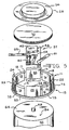
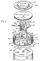
- FIGs 1 and 2 show a protection device 10 according to the present invention in the assembled form.
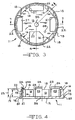
- the protection device 10 includes a protective housing 11 (shown also in Figures 3, 4 and 5) having a base 12. As shown in Figures 3, 4 and 5, extending from a primary surface 14 of the base 12 is a projecting shoulder 16 having a curved side wall 17 extending to an upper surface 18, which is generally parallel to the primary surface 14.
- the curved side wall 17 extends generally perpendicularly from the primary surface 14 so that the upper surface 18 is at a first distance 19 from the primary surface 14.
- the protective housing 11 also has a retaining clip 22 having an arcuate side wall 23 terminating in a hook portion 24.
- the hook portion 24 provides a retaining ledge 24A, which is generally parallel to the primary surface 14.
- the retaining ledge 24A is spaced from the primary surface 14 a second distance 25 above the primary surface 14. As shown in Figure 4, the second distance 25 is greater than the first distance 19.
- a material which is suitable for the protective housing 11 is Victrex (PEEK) 450-G manufactured by Victrex USA Inc. of Westchester, Pennsylvania, or alternatively a polyamide-imide available from DSM Engineering Plastic Products, Inc. of Reading, Pennsylvania as Torlon 4203 PAI. Also suitable for the protective housing 11 and available from DSM Engineering Plastic Products, Inc. is a material marketed under the name KetronTM PEEK 1000.
- Another material suitable for the protective housing 11 is liquid crystal polymer, commonly known as Zenite, and available from E.I. du Pont de Nemours and Company.
- molding orifices 27 are preferably provided in the base 12.
- the molding orifices 27 allow a portion of a mold to extend through the base 12 to form the retaining ledge 24A at the second distance 25. Once the retaining clips 22 are formed, the mold is withdrawn through the molding orifices 27.
- the protection device 10 also includes a terminal cap 28. As shown in Figures 1 and 2, a portion of a first side 31 of the terminal cap 28 rests on the upper surface 18 of the projecting shoulder 16. In addition, a portion of a second side 34 of the terminal cap 28 contacts the retaining ledge 24A of the retaining clip 22. The difference between the first distance 19 and the second distance 25 may be such that the terminal cap 28 is firmly held against the upper surface 18 of the projecting shoulder 16 and the retaining ledge 24A of the retaining clip 22, as shown in Figure 2.
- FIGS 5 and 6 show the relative position of an electrical component 37 with respect to the protection device 10.
- the electrical component 37 may include a fuse 40 and a diode 43 mounted on an insulating substrate 46. Those skilled in the art will recognize that the diode 43 and/or substrate 46 may be omitted depending on the particular intended application.
- a terminal pin 49 of a battery 52 extends through a contact hole 55 in the base 12 and is connected to a first lead 58 of the electrical component 37 by welding the first lead 58 to the terminal pin 49.
- a second lead 61 is connected to a header 64 of the battery 52 by passing the second lead 61 through one of the molding orifices 27.
- the second lead 61 may be electrically connected to the header 64 by welding.
- the present invention may include a compressible pad 70 for holding the electrical component 37 firmly in place.
- the compressible pad 70 contacts and is compressed between portions of the electrical component 37 and portions of the terminal cap 28.
- the compressible pad 70 may serve also to hold the terminal cap 28 firmly against the retaining clip 22 and off of projecting shoulder 16.
- an adhesive type material similar to that used in the prior art may be used.
- the compressible pad 70 is preferred because it reduces assembly costs and mess associated with the prior art adhesive material.
- the compressible pad 70 is a material which can withstand at least about 200°C, and is preferably a silicone based material.
- a silicone based material which is suitable for use in the compressible pad 70 is available from Furon Company of New Haven, Connecticut as product number R10470 and referred to by the trademark COHRlastic®.
- the protective housing 11 may be further prevented from rotating by providing a shelf 73, an edge 75 and a wrap 77.
- the shelf 73 is provided by positioning the retaining clip 22 to extend from a location on the primary surface 14 which is set back from a peripheral rim 83 of the base 12.
- the shelf 73 is defined by the intersections of the retaining clip 22 and the peripheral rim 83 with the primary surface 14.
- the shelf 73 is provided by positioning the projecting shoulder 16 to extend from a location on the primary surface 14 which is set back from the peripheral rim 83 so as to define the shelf 73 formed by the intersections of the projecting shoulder 16 and the peripheral rim 83 with the primary surface 14.
- the intersection of the shelf 73 and the peripheral rim 83 defines the edge 75.
- a wrap 77 When the base 12 is provided with the shelf 73, a wrap 77, shown in Figure 1, may be placed around a portion of the header 64 and a portion of the protective housing 11, including the shelf 73.
- the shelf 73 provides a discontinuity in the otherwise cylindrical surface covered by the wrap 77.
- the edge 75 extends into the wrap 77, thereby preventing the base 12 from rotating relative to the header 64 when the wrap 77 is sufficiently tight around the base 12 and battery 52.
- the wrap 77 is preferably made from an electrically insulating material such as polymerized tetrafluoroethylene or polyester. The wrap 77 may be heat-shrunk into the proper position.
- electrolyte is introduced through the header 64 using a fill hole. Once the battery 52 has the proper amount of electrolyte inside, the fill hole is closed usually by welding a metallic material to the header 64.
- the metallic material often extends from the header 64 as a metallic projection 86, shown in Figure 5. Although the metallic projection 86 does not extend far beyond the, header 64, since it is desirable to have the base 12 firmly supported by the header 64, an accommodating orifice 88 may be positioned in the base 12 to accommodate the metallic projection 86 therein.
- a means for fastening may be provided.
- the means for fastening may be a tinnerman fastener 92 which contacts the base 12, and attaches to a portion of the terminal pin 49 extending through the contact hole 55.
- the terminal cap 28 is preferably electrically conductive.
- a third lead 95 shown in Figures 2, 5 and 6, is electrically connected to the terminal cap 28.
- the third lead 95 may be electrically connected to the terminal cap 28 by welding.
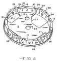
- Figure 8 shows an alternative embodiment of the protective housing 11.
- interstitial side walls 96 of the projecting shoulders 16 and retaining clips 22 are tapered so that the interstitial side walls 96 do not form a right angle with the primary surface 14, and instead form an acute angle ⁇ with the primary surface 14.
- rounded edges 97 on the projecting shoulders 16 and retaining clips 22 A mold having rounded edges 97 is easier to construct.
- Figure 8 shows ribs 98 on the retaining clips 22. The ribs 98 permit the material used to form the protective housing 22 to flow within the mold to completely and consistently form the retaining clips 22.
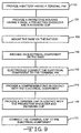
- FIG. 9 shows steps of a method according to the present invention in which a battery and an electrical component, such as those described above, are assembled.
- the method begins by providing (step 100) a battery having a terminal pin, and providing (step 103) a protective housing having a base with a contact hole therethrough, a projecting shoulder and a retaining clip.
- the base is mounted (step 106) on the battery so that the terminal pin extends into the contact hole.
- an electrical component is provided (step 109) on the base and electrically connected (step 112) to the terminal pin.
- a terminal cap is provided (step 118) in contact with the projecting shoulder and the retaining clip, and the terminal cap is electrically connected (step 121) to the electrical component.
- a compressible pad is provided (step 115) in contact with the electrical component.
- Figures 10 and 11 show an alternative embodiment of the present invention in which connecting walls 200 connect to the arcuate side wall 23 of the retaining clip 22, and connect to the curved side wall 17 of the projecting shoulder 16.
- the connecting walls 200 stiffen the retaining clips 22.
- Figure 11 also shows a variation on the projecting shoulder 16 described above.
- some of the projecting shoulders 16 have ribs 205 formed on the curved side wall 17. It should be noted that any number of the shoulders 16 may have ribs 205.
- the ribs 205 increase the size of the upper surface 18, and thereby prevent part of the terminal cap 28 from moving too close to the primary surface 14.
- Figure 12 shows an alternative embodiment of the present invention in which a gasket 300 is placed between the base 12 and the header 64.
- the gasket 300 allows the protection 10 to be seated firmly on the header 64, even when the header 64 or the base 12 has irregularities in it.
- a preferred gasket 300 is made from an aramid insulating paper, such as NomexTM, and is preferably approximately 0.013 inches thick.
- the gasket 300 may have one or more adhesive layers for bonding to the header 64 and/or the base 12.
- the gasket 300 may have a first adhesive layer 302 for bonding to the header 64, and may have a second adhesive layer 303 for bonding to the base 12. It should be noted that the thickness of the gasket 300 and the adhesive layers 302, 303 shown in Figure 12 are not drawn to scale in order that the gasket 300 and the adhesive layers 302, 303 can be more easily understood.
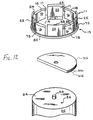
- Figure 13 shows an insulator 310 placed between the first side 31 of the terminal cap 28 and the electrical component 37.
- the insulator 310 is preferably made from an aramid insulating paper, such as NomexTM.
- the insulator 310 may have an adhesive layer on one or more sides.
- the insulator 310 may have an adhesive layer 315 for bonding the insulator 310 to the first side 31 of the terminal cap 28.
- the insulator 310 is approximately 0.008 inches thick. It should be noted that Figure 13 is not to scale with regard to the thickness of the insulator 310 and adhesive layer 315, so that the features of the insulator and adhesive layer 315 can be more easily understood.
Landscapes
- Chemical & Material Sciences (AREA)
- Chemical Kinetics & Catalysis (AREA)
- Electrochemistry (AREA)
- General Chemical & Material Sciences (AREA)
- Engineering & Computer Science (AREA)
- Manufacturing & Machinery (AREA)
- Microelectronics & Electronic Packaging (AREA)
- Connection Of Batteries Or Terminals (AREA)
- Battery Mounting, Suspending (AREA)
- Fuses (AREA)
- Emergency Protection Circuit Devices (AREA)
- Apparatus For Radiation Diagnosis (AREA)
Applications Claiming Priority (2)
| Application Number | Priority Date | Filing Date | Title |
|---|---|---|---|
| US09/538,917 US6317335B1 (en) | 1999-09-24 | 2000-03-30 | Stiffened protection device for protecting an electrical component |
| US538917 | 2000-03-30 |
Publications (3)
| Publication Number | Publication Date |
|---|---|
| EP1139702A2 true EP1139702A2 (de) | 2001-10-04 |
| EP1139702A3 EP1139702A3 (de) | 2002-07-10 |
| EP1139702B1 EP1139702B1 (de) | 2006-05-31 |
Family
ID=24148970
Family Applications (1)
| Application Number | Title | Priority Date | Filing Date |
|---|---|---|---|
| EP01302376A Expired - Lifetime EP1139702B1 (de) | 2000-03-30 | 2001-03-14 | Schutzvorrichtung für einen elektrischen Bauteil |
Country Status (5)
| Country | Link |
|---|---|
| US (1) | US6317335B1 (de) |
| EP (1) | EP1139702B1 (de) |
| JP (1) | JP2001283829A (de) |
| AT (1) | ATE328467T1 (de) |
| DE (1) | DE60120029T2 (de) |
Cited By (3)
| Publication number | Priority date | Publication date | Assignee | Title |
|---|---|---|---|---|
| EP1204154A3 (de) * | 2000-08-22 | 2002-08-07 | Wilson Greatbatch Ltd. | Schutzvorrichtung und Methode zur Bestimmung einer Temperaturbelastung |
| EP1152476A3 (de) * | 2000-05-05 | 2003-01-22 | Wilson Greatbatch Limited | Schutzvorrichtung mit konischen Rippen und Verfahren zum Zusammenbauen einer Batterie mit einer Schutzvorrichtung und einem elektrischen Bauteil |
| US6671187B1 (en) | 1999-09-24 | 2003-12-30 | Wilson Greatbatch Ltd. | Protection device having a sleeve and method of assembling a battery with a protection device and an electrical component |
Families Citing this family (13)
| Publication number | Priority date | Publication date | Assignee | Title |
|---|---|---|---|---|
| JP4064045B2 (ja) * | 2000-09-01 | 2008-03-19 | 株式会社日立製作所 | 樹脂ブロック絶縁システム |
| EP1246276A3 (de) | 2001-03-26 | 2004-01-14 | Wilson Greatbatch Ltd. | Verbindungsschmelzsicherung |
| CA2379009C (en) * | 2001-03-27 | 2012-05-22 | Wilson Greatbatch Ltd. | Trace fuse for a battery termination |
| US6574111B1 (en) * | 2002-05-26 | 2003-06-03 | Motorola, Inc. | Impact resistant rechargeable battery cell with crumple zone |
| US6831827B1 (en) | 2002-10-30 | 2004-12-14 | Wilson Greatbatch Technologies, Inc. | Universal family spacers for a battery electrical protection device |
| US7688596B1 (en) | 2007-04-19 | 2010-03-30 | Electrochem Solutions, Inc. | Electrochemical cell supporting a protective housing for electrical components |
| US20110262787A1 (en) | 2010-04-23 | 2011-10-27 | Hosein Maleki | Electrochemical Cell with Reduced Magnetic Field Emission and Corresponding Devices |
| US20110262779A1 (en) | 2010-04-23 | 2011-10-27 | Hossein Maleki | Electrochemical Cell with Reduced Magnetic Field Emission and Corresponding Devices |
| US8642205B2 (en) | 2010-08-09 | 2014-02-04 | Motorola Mobility Llc | Electrochemical battery pack with reduced magnetic field emission and corresponding devices |
| KR101219955B1 (ko) * | 2010-11-30 | 2013-01-08 | 기아자동차주식회사 | 고전압 배터리의 서비스플러그 |
| DE102011089839A1 (de) | 2011-12-23 | 2013-06-27 | Robert Bosch Gmbh | Berührschutz für stromleitende Anschlusselemente sowie ein Kraftfahrzeug mit einer Lithium-Ionen-Batterie |
| US10050300B2 (en) | 2013-03-11 | 2018-08-14 | Google Technology Holdings LLC | Electrochemical cell with multi-faceted geometry |
| KR102177503B1 (ko) * | 2014-04-11 | 2020-11-11 | 삼성에스디아이 주식회사 | 이차 전지 |
Family Cites Families (25)
| Publication number | Priority date | Publication date | Assignee | Title |
|---|---|---|---|---|
| US3663301A (en) | 1970-04-09 | 1972-05-16 | Mallory & Co Inc P R | Leak-proof primary cell |
| US3841913A (en) | 1972-12-15 | 1974-10-15 | Esb Inc | Unitary cathode cover |
| US4047790A (en) | 1976-01-07 | 1977-09-13 | General Electric Company | Insulative header assembly with feed through terminals |
| US4302517A (en) | 1980-06-26 | 1981-11-24 | Union Carbide Corporation | Unitary seal and cover support gasket for miniature button cells |
| CA1179730A (en) | 1982-06-16 | 1984-12-18 | Marian Wiacek | Snap-in sealing and insulating member for galvanic cells |
| FR2562719B1 (fr) | 1984-04-05 | 1987-02-27 | Accumulateurs Fixes | Montage ameliore de piles ou batteries de piles |
| DE3742026A1 (de) | 1987-12-11 | 1989-06-22 | Varta Batterie | Kunststoffdichtungselement fuer galvanische primaerelemente |
| US5589293A (en) | 1988-05-05 | 1996-12-31 | Duracell Inc. | Sealed galvanic cell with injection molded top |
| JPH0461857U (de) | 1990-10-05 | 1992-05-27 | ||
| US5283137A (en) | 1991-04-29 | 1994-02-01 | Optima Batteries, Inc. | Cover assembly for rechargeable battery |
| JP3203623B2 (ja) | 1992-03-06 | 2001-08-27 | ソニー株式会社 | 有機電解液電池 |
| US5264303A (en) | 1992-06-01 | 1993-11-23 | The United States Of America As Represented By The Secretary Of The Army | Battery housing and cap |
| DE4413808B4 (de) | 1993-04-27 | 2007-06-06 | Medtronic, Inc., Minneapolis | Verfahren zur Herstellung einer Baugruppe für eine elektrochemische Zelle, Verfahren zum Zusammenbauen einer elektrochemischen Zelle und Knopfzelle |
| US5434017A (en) | 1993-11-19 | 1995-07-18 | Medtronic, Inc. | Isolated connection for an electrochemical cell |
| US5672443A (en) | 1994-04-15 | 1997-09-30 | Phillips Plastics Corporation | Battery sealing cap |
| IL114881A (en) | 1994-08-24 | 1998-01-04 | Duracell Inc | Electrochemical cell gasket support disc |
| IL114880A (en) | 1994-08-24 | 1998-09-24 | Duracell Inc | Electrochemical cell gasket |
| US5532081A (en) | 1994-08-24 | 1996-07-02 | Duracell Inc. | Upward deflecting support disk for electrochemical cell seal |
| US5529858A (en) | 1994-10-24 | 1996-06-25 | Saft America, Inc. | Hermetically sealed thermocompression feedthrough and peripheral seal for high temperature lithium based battery applications |
| US5776631A (en) | 1995-12-06 | 1998-07-07 | Eveready Battery Company, Inc. | Safety snap-through seal for galvanic cells |
| US5786980A (en) | 1996-02-02 | 1998-07-28 | Evans Capacitor Company, Incorporated | Electrical component package and packaged electrical component |
| US5770328A (en) | 1996-07-05 | 1998-06-23 | Motorola, Inc. | Battery packaging system and clip for same |
| US5821010A (en) | 1997-02-07 | 1998-10-13 | Eveready Battery Company, Inc. | Galvanic cell having a reliable sealable vent closure |
| US5843597A (en) | 1997-12-01 | 1998-12-01 | Eveready Battery Company, Inc. | Ribbed gasket for miniature galvanic cell |
| US6205034B1 (en) * | 1999-09-24 | 2001-03-20 | Wilson Greatbatch Ltd. | Protection device for protecting an electrical component and method of assembling a battery with a protection device and an electrical component |
-
2000
- 2000-03-30 US US09/538,917 patent/US6317335B1/en not_active Expired - Lifetime
-
2001
- 2001-03-05 JP JP2001059434A patent/JP2001283829A/ja active Pending
- 2001-03-14 EP EP01302376A patent/EP1139702B1/de not_active Expired - Lifetime
- 2001-03-14 DE DE60120029T patent/DE60120029T2/de not_active Expired - Fee Related
- 2001-03-14 AT AT01302376T patent/ATE328467T1/de not_active IP Right Cessation
Cited By (3)
| Publication number | Priority date | Publication date | Assignee | Title |
|---|---|---|---|---|
| US6671187B1 (en) | 1999-09-24 | 2003-12-30 | Wilson Greatbatch Ltd. | Protection device having a sleeve and method of assembling a battery with a protection device and an electrical component |
| EP1152476A3 (de) * | 2000-05-05 | 2003-01-22 | Wilson Greatbatch Limited | Schutzvorrichtung mit konischen Rippen und Verfahren zum Zusammenbauen einer Batterie mit einer Schutzvorrichtung und einem elektrischen Bauteil |
| EP1204154A3 (de) * | 2000-08-22 | 2002-08-07 | Wilson Greatbatch Ltd. | Schutzvorrichtung und Methode zur Bestimmung einer Temperaturbelastung |
Also Published As
| Publication number | Publication date |
|---|---|
| ATE328467T1 (de) | 2006-06-15 |
| US6317335B1 (en) | 2001-11-13 |
| JP2001283829A (ja) | 2001-10-12 |
| DE60120029T2 (de) | 2006-12-14 |
| EP1139702B1 (de) | 2006-05-31 |
| DE60120029D1 (de) | 2006-07-06 |
| EP1139702A3 (de) | 2002-07-10 |
Similar Documents
| Publication | Publication Date | Title |
|---|---|---|
| EP1087456B1 (de) | Schutzvorrichtung für ein elektrisches Bauteil und Verfahren zum Zusammenbau einer Batterie mit diesem elektrischen Bauteil und der Schutzvorrichtung | |
| EP1139702B1 (de) | Schutzvorrichtung für einen elektrischen Bauteil | |
| KR100878285B1 (ko) | 배터리 팩 | |
| US6437239B1 (en) | Protection device and method of determining exposure temperature | |
| EP1032060B1 (de) | Batterie-Pack | |
| JP4537958B2 (ja) | リチウムイオン電池 | |
| EP2400578B1 (de) | Sekundärbatterie | |
| EP2058876B1 (de) | Sekundärbatterie und Verfahren zu deren Herstellung | |
| KR102092764B1 (ko) | 배터리 팩과 배터리 팩을 조립하는 방법 | |
| US20060024573A1 (en) | Secondary battery | |
| CN101409333B (zh) | 电池组 | |
| US20090155684A1 (en) | Protection circuit assembly and battery pack having the same | |
| US20050221176A1 (en) | Prismatic-type rechargeable battery with attached lead plate | |
| US6426867B1 (en) | Protection device having tapered ribs and method of assembling a battery with a protection device and an electrical component | |
| JP5683252B2 (ja) | 外付けptc素子ユニット及び電池 | |
| JP4357839B2 (ja) | アルカリ電池用の端部シールアッセンブリ | |
| KR100696782B1 (ko) | 리튬이온 이차전지 | |
| CA2346221C (en) | Protection device having a sleeve and method of assembling a battery with a protection device and an electrical component | |
| US7688596B1 (en) | Electrochemical cell supporting a protective housing for electrical components | |
| WO2025039784A1 (zh) | 温度传感器、电池、电池包及其健康检测方法、评估方法、监测系统 | |
| KR101100913B1 (ko) | 안전 배기 조립체 및 이의 제조 방법과 안전 배기 조립체를 구비하는 전지 | |
| US6831827B1 (en) | Universal family spacers for a battery electrical protection device | |
| EP4439787A2 (de) | Batteriepack | |
| KR20160075298A (ko) | 내구성이 우수한 이차전지용 캡조립체의 제조방법 및 그 조립체 | |
| CN216214328U (zh) | 一种用于导线焊接接头处的保护壳 |
Legal Events
| Date | Code | Title | Description |
|---|---|---|---|
| PUAI | Public reference made under article 153(3) epc to a published international application that has entered the european phase |
Free format text: ORIGINAL CODE: 0009012 |
|
| AK | Designated contracting states |
Kind code of ref document: A2 Designated state(s): AT BE CH CY DE DK ES FI FR GB GR IE IT LI LU MC NL PT SE TR |
|
| AX | Request for extension of the european patent |
Free format text: AL;LT;LV;MK;RO;SI |
|
| PUAL | Search report despatched |
Free format text: ORIGINAL CODE: 0009013 |
|
| AK | Designated contracting states |
Kind code of ref document: A3 Designated state(s): AT BE CH CY DE DK ES FI FR GB GR IE IT LI LU MC NL PT SE TR |
|
| AX | Request for extension of the european patent |
Free format text: AL;LT;LV;MK;RO;SI |
|
| RIC1 | Information provided on ipc code assigned before grant |
Free format text: 7H 05K 1/02 A, 7H 01M 10/42 B, 7H 01M 10/48 B |
|
| 17P | Request for examination filed |
Effective date: 20020515 |
|
| AKX | Designation fees paid |
Designated state(s): AT BE CH CY DE DK ES FI FR GB GR IE IT LI LU MC NL PT SE TR |
|
| 17Q | First examination report despatched |
Effective date: 20041105 |
|
| GRAP | Despatch of communication of intention to grant a patent |
Free format text: ORIGINAL CODE: EPIDOSNIGR1 |
|
| GRAS | Grant fee paid |
Free format text: ORIGINAL CODE: EPIDOSNIGR3 |
|
| GRAA | (expected) grant |
Free format text: ORIGINAL CODE: 0009210 |
|
| AK | Designated contracting states |
Kind code of ref document: B1 Designated state(s): AT BE CH CY DE DK ES FI FR GB GR IE IT LI LU MC NL PT SE TR |
|
| PG25 | Lapsed in a contracting state [announced via postgrant information from national office to epo] |
Ref country code: AT Free format text: LAPSE BECAUSE OF FAILURE TO SUBMIT A TRANSLATION OF THE DESCRIPTION OR TO PAY THE FEE WITHIN THE PRESCRIBED TIME-LIMIT Effective date: 20060531 Ref country code: NL Free format text: LAPSE BECAUSE OF FAILURE TO SUBMIT A TRANSLATION OF THE DESCRIPTION OR TO PAY THE FEE WITHIN THE PRESCRIBED TIME-LIMIT Effective date: 20060531 Ref country code: CH Free format text: LAPSE BECAUSE OF FAILURE TO SUBMIT A TRANSLATION OF THE DESCRIPTION OR TO PAY THE FEE WITHIN THE PRESCRIBED TIME-LIMIT Effective date: 20060531 Ref country code: LI Free format text: LAPSE BECAUSE OF FAILURE TO SUBMIT A TRANSLATION OF THE DESCRIPTION OR TO PAY THE FEE WITHIN THE PRESCRIBED TIME-LIMIT Effective date: 20060531 Ref country code: BE Free format text: LAPSE BECAUSE OF FAILURE TO SUBMIT A TRANSLATION OF THE DESCRIPTION OR TO PAY THE FEE WITHIN THE PRESCRIBED TIME-LIMIT Effective date: 20060531 Ref country code: FI Free format text: LAPSE BECAUSE OF FAILURE TO SUBMIT A TRANSLATION OF THE DESCRIPTION OR TO PAY THE FEE WITHIN THE PRESCRIBED TIME-LIMIT Effective date: 20060531 Ref country code: IT Free format text: LAPSE BECAUSE OF FAILURE TO SUBMIT A TRANSLATION OF THE DESCRIPTION OR TO PAY THE FEE WITHIN THE PRESCRIBED TIME-LIMIT;WARNING: LAPSES OF ITALIAN PATENTS WITH EFFECTIVE DATE BEFORE 2007 MAY HAVE OCCURRED AT ANY TIME BEFORE 2007. THE CORRECT EFFECTIVE DATE MAY BE DIFFERENT FROM THE ONE RECORDED. Effective date: 20060531 |
|
| REG | Reference to a national code |
Ref country code: CH Ref legal event code: EP Ref country code: GB Ref legal event code: FG4D |
|
| RAP2 | Party data changed (patent owner data changed or rights of a patent transferred) |
Owner name: WILSON GREATBATCH LIMITED |
|
| REG | Reference to a national code |
Ref country code: IE Ref legal event code: FG4D |
|
| REF | Corresponds to: |
Ref document number: 60120029 Country of ref document: DE Date of ref document: 20060706 Kind code of ref document: P |
|
| NLT2 | Nl: modifications (of names), taken from the european patent patent bulletin |
Owner name: WILSON GREATBATCH LIMITED Effective date: 20060621 |
|
| REG | Reference to a national code |
Ref country code: SE Ref legal event code: TRGR |
|
| PG25 | Lapsed in a contracting state [announced via postgrant information from national office to epo] |
Ref country code: DK Free format text: LAPSE BECAUSE OF FAILURE TO SUBMIT A TRANSLATION OF THE DESCRIPTION OR TO PAY THE FEE WITHIN THE PRESCRIBED TIME-LIMIT Effective date: 20060831 |
|
| PG25 | Lapsed in a contracting state [announced via postgrant information from national office to epo] |
Ref country code: ES Free format text: LAPSE BECAUSE OF FAILURE TO SUBMIT A TRANSLATION OF THE DESCRIPTION OR TO PAY THE FEE WITHIN THE PRESCRIBED TIME-LIMIT Effective date: 20060911 |
|
| PG25 | Lapsed in a contracting state [announced via postgrant information from national office to epo] |
Ref country code: PT Free format text: LAPSE BECAUSE OF FAILURE TO SUBMIT A TRANSLATION OF THE DESCRIPTION OR TO PAY THE FEE WITHIN THE PRESCRIBED TIME-LIMIT Effective date: 20061031 |
|
| NLV1 | Nl: lapsed or annulled due to failure to fulfill the requirements of art. 29p and 29m of the patents act | ||
| REG | Reference to a national code |
Ref country code: CH Ref legal event code: PL |
|
| ET | Fr: translation filed | ||
| PLBE | No opposition filed within time limit |
Free format text: ORIGINAL CODE: 0009261 |
|
| STAA | Information on the status of an ep patent application or granted ep patent |
Free format text: STATUS: NO OPPOSITION FILED WITHIN TIME LIMIT |
|
| 26N | No opposition filed |
Effective date: 20070301 |
|
| PG25 | Lapsed in a contracting state [announced via postgrant information from national office to epo] |
Ref country code: MC Free format text: LAPSE BECAUSE OF NON-PAYMENT OF DUE FEES Effective date: 20070331 Ref country code: IE Free format text: LAPSE BECAUSE OF NON-PAYMENT OF DUE FEES Effective date: 20070314 |
|
| PG25 | Lapsed in a contracting state [announced via postgrant information from national office to epo] |
Ref country code: GR Free format text: LAPSE BECAUSE OF FAILURE TO SUBMIT A TRANSLATION OF THE DESCRIPTION OR TO PAY THE FEE WITHIN THE PRESCRIBED TIME-LIMIT Effective date: 20060901 |
|
| PGFP | Annual fee paid to national office [announced via postgrant information from national office to epo] |
Ref country code: GB Payment date: 20080327 Year of fee payment: 8 Ref country code: SE Payment date: 20080327 Year of fee payment: 8 |
|
| PGFP | Annual fee paid to national office [announced via postgrant information from national office to epo] |
Ref country code: DE Payment date: 20080430 Year of fee payment: 8 Ref country code: FR Payment date: 20080317 Year of fee payment: 8 |
|
| PG25 | Lapsed in a contracting state [announced via postgrant information from national office to epo] |
Ref country code: LU Free format text: LAPSE BECAUSE OF NON-PAYMENT OF DUE FEES Effective date: 20070314 Ref country code: CY Free format text: LAPSE BECAUSE OF FAILURE TO SUBMIT A TRANSLATION OF THE DESCRIPTION OR TO PAY THE FEE WITHIN THE PRESCRIBED TIME-LIMIT Effective date: 20060531 |
|
| PG25 | Lapsed in a contracting state [announced via postgrant information from national office to epo] |
Ref country code: TR Free format text: LAPSE BECAUSE OF FAILURE TO SUBMIT A TRANSLATION OF THE DESCRIPTION OR TO PAY THE FEE WITHIN THE PRESCRIBED TIME-LIMIT Effective date: 20060531 |
|
| EUG | Se: european patent has lapsed | ||
| GBPC | Gb: european patent ceased through non-payment of renewal fee |
Effective date: 20090314 |
|
| REG | Reference to a national code |
Ref country code: FR Ref legal event code: ST Effective date: 20091130 |
|
| PG25 | Lapsed in a contracting state [announced via postgrant information from national office to epo] |
Ref country code: DE Free format text: LAPSE BECAUSE OF NON-PAYMENT OF DUE FEES Effective date: 20091001 |
|
| PG25 | Lapsed in a contracting state [announced via postgrant information from national office to epo] |
Ref country code: FR Free format text: LAPSE BECAUSE OF NON-PAYMENT OF DUE FEES Effective date: 20091123 Ref country code: GB Free format text: LAPSE BECAUSE OF NON-PAYMENT OF DUE FEES Effective date: 20090314 |
|
| PG25 | Lapsed in a contracting state [announced via postgrant information from national office to epo] |
Ref country code: SE Free format text: LAPSE BECAUSE OF NON-PAYMENT OF DUE FEES Effective date: 20090315 |