EP1142467A1 - Dispositif de cueillette de céréales - Google Patents
Dispositif de cueillette de céréales Download PDFInfo
- Publication number
- EP1142467A1 EP1142467A1 EP01107119A EP01107119A EP1142467A1 EP 1142467 A1 EP1142467 A1 EP 1142467A1 EP 01107119 A EP01107119 A EP 01107119A EP 01107119 A EP01107119 A EP 01107119A EP 1142467 A1 EP1142467 A1 EP 1142467A1
- Authority
- EP
- European Patent Office
- Prior art keywords
- attachment device
- frame
- frame part
- crops according
- cover
- Prior art date
- Legal status (The legal status is an assumption and is not a legal conclusion. Google has not performed a legal analysis and makes no representation as to the accuracy of the status listed.)
- Granted
Links
- 238000003306 harvesting Methods 0.000 claims abstract description 23
- 238000013016 damping Methods 0.000 claims description 7
- 239000006096 absorbing agent Substances 0.000 claims description 2
- 230000035939 shock Effects 0.000 claims description 2
- 210000000056 organ Anatomy 0.000 description 7
- 230000007246 mechanism Effects 0.000 description 6
- 235000013399 edible fruits Nutrition 0.000 description 4
- 238000000034 method Methods 0.000 description 4
- 230000008569 process Effects 0.000 description 4
- 238000010276 construction Methods 0.000 description 3
- 230000000903 blocking effect Effects 0.000 description 2
- 230000008878 coupling Effects 0.000 description 2
- 238000010168 coupling process Methods 0.000 description 2
- 238000005859 coupling reaction Methods 0.000 description 2
- 230000009471 action Effects 0.000 description 1
- 238000011109 contamination Methods 0.000 description 1
- 238000010586 diagram Methods 0.000 description 1
- 238000005553 drilling Methods 0.000 description 1
- 230000000694 effects Effects 0.000 description 1
- 230000002996 emotional effect Effects 0.000 description 1
- 230000005484 gravity Effects 0.000 description 1
- 230000008439 repair process Effects 0.000 description 1
- 239000004575 stone Substances 0.000 description 1
Images

Classifications
-
- A—HUMAN NECESSITIES
- A01—AGRICULTURE; FORESTRY; ANIMAL HUSBANDRY; HUNTING; TRAPPING; FISHING
- A01D—HARVESTING; MOWING
- A01D41/00—Combines, i.e. harvesters or mowers combined with threshing devices
- A01D41/12—Details of combines
- A01D41/14—Mowing tables
- A01D41/144—Foldable headers
-
- A—HUMAN NECESSITIES
- A01—AGRICULTURE; FORESTRY; ANIMAL HUSBANDRY; HUNTING; TRAPPING; FISHING
- A01D—HARVESTING; MOWING
- A01D45/00—Harvesting of standing crops
- A01D45/02—Harvesting of standing crops of maize, i.e. kernel harvesting
- A01D45/021—Cornheaders
Definitions
- the invention relates to an attachment for harvesting stalky crops according to the preamble of claim 1.
- the invention is therefore based on the object of an attachment for harvesting stalked To design crops so that the in the swivel range between the middle part and the or the pivoting side panels arranged covers in a structurally simple manner in a collision-free position during the pivoting process of the side parts can and are still able to avoid obstacles in the working position to dodge.
- the task is performed using a front attachment for harvesting stalky crops the characterizing features of claim 1 solved.
- the at least one cover element arranged in the pivoting area is arranged transversely to the Direction of travel axis is articulated on an intermediate frame, which in turn by a Axis pointing in the direction of travel with the main frame of the front attachment in operative connection stands, it is ensured that the cover hood on the one hand when pivoting the side parts of the working position in the transport position and vice versa in a collision avoiding position can be spent. On the other hand, this is about an axis running transversely to the direction of travel swiveling cover element in the working position when hitting an obstacle in the vertical Direction pivotable in a position to avoid damage.
- the cover elements are in an advantageous embodiment of the invention in two parts in the form of a front and a rear Cover hood executed.
- the front and the rear cover can be articulated with each other, with only the rear cover over the cross axis extending to the direction of travel is pivotally connected to the intermediate frame. On in this way it is ensured that the cover hoods forming the cover element upon impact collapse onto an obstacle in a space-saving manner and move the objects to be moved Masses remain low.
- the front and rear covers also articulated to one another via a common support frame be connected, with such an embodiment of the support frame across the Direction of travel axis is articulated on the intermediate frame.
- the covering hoods can hit an obstacle at least one damping element can be assigned.
- this damping element simplifies construction as a hydraulic and / or pneumatic and / or mechanical shock absorbers.
- the pivoting movement of the side frame parts of the front attachment and the respective cover elements assigned intermediate frame is in a further advantageous embodiment the invention realized by lifting cylinders.
- the respective lifting cylinder of the side frame parts with the lifting cylinder of the the respective side frame part operatively connected intermediate frame through parallel connection coupled with each other.
- those are coupled to one another by parallel connection Lift cylinder dimensioned so that when swiveling from the working to the transport position Always first cover element connected to the intermediate frame into a collision-avoiding one Position is pivoted before the respective side frame part in the transport position emotional.
- each cover can be in a further advantageous embodiment of the invention be designed lockable in the working position, so that their pivoting around Axis transverse to the direction of travel is blocked.
- the locking function can also in flat and unobstructed terrain can be used to a low-vibration To achieve the arrangement of the covers.
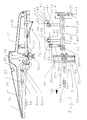
- Figure 1 shows an attachment 1 according to the invention which in its rear area in is not adapted to a carrier vehicle 2, the carrier vehicle 2 can be designed, for example, as a combine harvester or chopper.
- the header 1 divided into a central part 3 which is connected directly to the carrier vehicle 2 and which is in its edge regions in the direction of travel FR pivots 4.
- the pivot axes 4 are gripped by holding flanges 5, the other ends rotatably with pivotable side parts 6 are connected, in Figure 1, the left side part 6 in the ground-level working position and right side part 6 is shown in a transport position lying above the middle part 3.
- the non-pivotable middle part 3 lifting cylinders 7, 8 articulated, their piston rods 9, 10 via a coupling mechanism 11, the middle part 3 with the respective side parts 6 Connect rotatably, deviating from the version shown, the piston rod 9, 10 can also be arranged directly on the respective side part 6.
- a pressurization the lifting cylinder 7, 8 leads through the pressure source of the carrier vehicle 2, not shown, depending on Direction of movement of the respective piston rod 9, 10 for raising or lowering the side parts 6.
- the front attachment 1 Due to the multipart nature of the front attachment 1, its main frame 12 is subdivided into a center frame part 13 and side frame parts 14 pivotally associated therewith.
- each pair of picking rollers 15, 16 are between them on the upper side assigned a picking gap 17 forming picking plates 18, through whose picking gap 17 one of the stalk 19 of the stalks 19 which is gripped is pulled through, the fruit stalks 20 being on stripped the picking plates 18 and by means of conveyor chains 21 in the rear area of the Picking rollers 15 are promoted.
- the front attachment is 1 in the rear area of the picking rollers 15, a cross screw 22 assigned to the from the conveyor chains 21 in this area brought together fruit stands 20 in the middle and transfers them to the carrier vehicle 2 in a manner known per se.
- the cover elements 23-25 are composed of a front cover 26 and a rear cover protruding at least partially into this front cover 26 27 together. Both covers 26, 27 can be pivoted via a support frame 28 connected to each other, the front cover 26 on the extension 34 of the lies in its interior extending front support tube 29 and the rear cover 27 with the rear support tube 30 of the support frame 28 arranged in the interior thereof is connected.
- the Front support tube 29 has at its rear end a transverse web 31 and limiting flanges 32 holding fork 33. In the front area is the front support tube 29th a web-shaped extension 34 is formed.
- the rear support tube 30 takes in its front area a crossbar 35 which within the limiting flanges 32 in the holding fork 33 of the engages front support tube 29 and with this around a transverse to the direction FR Axis 36 is pivotally connected, so that the front cover 26 and the rear Cover 27 in the vertical direction in its position relative to one another about axis 36 are.
- a transverse web 37 is arranged in a rotationally fixed manner, which is traversed by a pivot axis 38 running transversely to the direction of travel FR.
- the intermediate frame 39 is formed by a frame structure 40 which is in its rear Area has a fork-shaped support 41 for receiving the pivot axis 38.
- the frame structure 40 has two in the area of the central part 3 of the attachment 1 projecting transverse webs 42 which are forked at one end Brackets 43 are formed.
- the middle frame part 13 are in the region of the fork-shaped Brackets 43 of the crossbars 42 assigned support points 44, which are by means of screw connections 45, 46 receive the intermediate frame 39 so that it can pivot about axes 47 pointing in the direction of travel FR.
- the intermediate frame 39 receives a further support 48, which by a the piston rod 50 of a lifting cylinder 51 receiving pin 49 rotatably penetrates becomes.
- the lifting cylinder can be pivoted about an axis 52 pointing in the direction of travel FR attached to the middle frame part 13.
- the main supporting profile 53 of the intermediate frame 39 has a double flange penetrated by bores 54 55 integrally formed, which is pivotally penetrated by a web profile 56, the The inclination of the web profile 56 is adjustable by means of the holes 54, so that the inclination of the front Support tube 29 and thus the inclination of the front cover 26 to different Harvest conditions can be adjusted.
- the web profile 56 is with a front around a roller 58 oriented transversely to the direction of travel FR 57, which the wear occurring due to the friction between the web profile 56 and the front support tube 29 should reduce.
- the roller 58 receiving and over the Double flange 55 in the inclination adjustable web profile 56 directly in a manner not shown the respective frame part 13, 14 pivotally attached, since here the intermediate frame according to the invention 39 is not required.
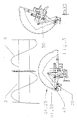
- FIG. 3 is the pivoting in the pivoting area between the middle part 3 and the side parts 6 positioned cover elements 24, 25 explained using the example of cover element 25, the intermediate frame 39 and the lifting cylinder 51 are mirror images of the cover element 24 are to be arranged.
- the cover element 25 is located in FIG the working position in a horizontal, in the swivel range between the middle part 3 and the respective side part 6 arranged position, which a pivoting of the respective side parts 6th severely impair or make impossible. If the "retracted" in the working position Lifting cylinder 51 pressurized, the piston rod 50 emerges from the lifting cylinder 51 and pivots the intermediate frame 39 about axis 47 into the right-hand illustration in FIG. 3, shown position.
- the respective cover element 24, 25 is removed from the swivel range pivoted out between the middle part 3 and the respective side part 6 of the front attachment 1, so that the side parts 6 move easily from the working to the transport position can be.
- the lifting cylinder 51 by any executed actuator 59 can be replaced, which is able to the intermediate frame 39 around To pivot axis 47.
- the pivot axis 47 (FIG. 2) of the intermediate frame 39 pointing in the direction of travel FR can also be arranged on the respective side frame part 14 of the side parts 6, so that the cover elements 24, 25 do not move towards the central part 3 as shown, but rather into FIG Swivel the direction of the side parts 6 into a collision avoiding position.
- this is achieved in that the transverse webs 42 are arranged on the intermediate frame 39 in the direction of the side parts 6.
- the front and the rear cover hoods 26, 27 of each cover element 23-25 can also have such a stability that the support frame 28 can be dispensed with.
- the front and rear covers 26, 27 would then be directly connected to one another in an articulated manner, with the rear cover 27 then directly receiving the pivot axis 38 extending transversely to the direction of travel in its rear region.
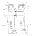
- Piston surface and piston rod side are the lifting cylinders 7; 8 ( Figure 4) from check valve 60 and throttle valve 61 are assigned to existing blocking blocks 62-65, each of which piston block-side locking blocks 63, 64 and the piston rod-side locking blocks 62, 65 over the line system 66, 67 are interconnected.
- Each intermediate frame 39 takes according to Figure 2 as double-acting lifting cylinders 51 designed actuators 59.
- Each of these lifting cylinders 51 according to the invention, an unlockable check valve 68, 69 is assigned on the piston surface side, each of the unlockable check valves 68, 69 also in the piping system 66 is integrated (Fig. 4).
- the lifting cylinders 51 with the line system 67 are on the piston rod side connected.
- the lifting cylinders 7, 8, 51 are parallel via the line systems 66, 67 switched.
- Each of the line systems 66, 67 also has connection lines 70, 71, which are connected to the pressure source, not shown, of the carrier vehicle 2.
- the Lifting cylinders 7, 8, 51 dimensioned such that the lifting cylinders move the piston rods 50 51 pressures required are significantly lower than those required to retract or extend the piston rods 9, 10 of the lifting cylinders 7, 8 necessary pressures.
- the switching arrangement shown in Figure 4 shows the transport position in which the piston rods 9, 10 of the lifting cylinders 7, 8 in the retracted position and the piston rods 50 of the lifting cylinders 51 are in the extended position.
- the side parts 6 are over the Middle part 3 ( Figure 1, right side) and the cover elements (24, 25) in an outside of Position swiveled position ( Figure 2, right representation) pivoted.
- the line system 66 is pressurized via the connecting line 70.
- the cover elements 24, 25 according to the invention be pivoted into a collision avoiding position.
- Another pressurization of line system 70 now leads via the throttle valves 61 of the blocking blocks 62, 65 to retract the piston rods 9, 10 in the lifting cylinders 7, 8, the side parts 6 in the Transport position are pivoted.
- the side parts 6 solve their Upward movement now a switching pulse I2 from the unlockable check valves 68, 69th switches back to the position shown in FIG. 4. After this, the swiveling process, start from the beginning as described.
- one of each is Line systems 66, 67 with the associated connecting line 70, 71 relieved of pressure.
- a damping element 72 can be assigned to the support frame 28 according to FIG be, which dampens the vertical pivoting movement of the cover elements 23-25.
- the damping element 72 can be designed as a gas pressure spring 73, which ends arranged pivotably on the support frame 28 or directly on the respective rear cover 27 is.
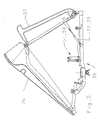
- the gas pressure spring 73 is either articulated with the invention Intermediate frame 39 (cover elements 24, 25) or the respective frame part 13, 14 (cover element 23) connected, so that the cover elements 23-25 come into contact with an obstacle Can take position according to Figure 5, the swinging back after overcoming the obstacle the cover elements 23-25 is supported by the gas pressure spring 73. It can also the pivoting according to Figure 5 to carry out repair work can also be done by hand.
- the cover elements consisting of a front and a rear cover 26, 27 24, 25 can be pivoted into their collision avoiding positions without the covers 26, 27 swing by the action of gravity around the pivot axes 38, they are lockable to the respective intermediate frame 39 by means of a locking mechanism 74 (FIG. 2).
- the locking takes place via the actuation of an adjusting lever 75 which is in one in the vertical direction on the support frame 28 of the covers 26, 27 pins 76 engages and so its vertical movement and thus also the vertical movement of the hoods 26, 27 blocked.
- the adjustment mechanism 74 is arranged directly on the respective frame part 13, 14.
- pivoting mechanism for cover elements 23-25 not limited to the attachment 1 designed for picking fruit stalks 20 is, but on arbitrarily designed agricultural implements, such as Attachments for whole plant harvesting can be used to achieve the effects described to achieve.
Landscapes
- Life Sciences & Earth Sciences (AREA)
- Environmental Sciences (AREA)
- Agricultural Machines (AREA)
- Harvesting Machines For Specific Crops (AREA)
- Harvester Elements (AREA)
- Catching Or Destruction (AREA)
- Cultivation Of Plants (AREA)
- Greenhouses (AREA)
Applications Claiming Priority (2)
| Application Number | Priority Date | Filing Date | Title |
|---|---|---|---|
| DE10016824A DE10016824A1 (de) | 2000-04-06 | 2000-04-06 | Vorrichtung zum Pflücken der Fruchtstände stängeliger Erntegüter |
| DE10016824 | 2000-04-06 |
Publications (2)
| Publication Number | Publication Date |
|---|---|
| EP1142467A1 true EP1142467A1 (fr) | 2001-10-10 |
| EP1142467B1 EP1142467B1 (fr) | 2004-06-02 |
Family
ID=7637613
Family Applications (1)
| Application Number | Title | Priority Date | Filing Date |
|---|---|---|---|
| EP01107119A Expired - Lifetime EP1142467B1 (fr) | 2000-04-06 | 2001-03-22 | Dispositif de cueillette de céréales |
Country Status (5)
| Country | Link |
|---|---|
| EP (1) | EP1142467B1 (fr) |
| AT (1) | ATE268105T1 (fr) |
| DE (2) | DE10016824A1 (fr) |
| HU (1) | HUP0101406A3 (fr) |
| PL (1) | PL346828A1 (fr) |
Cited By (11)
| Publication number | Priority date | Publication date | Assignee | Title |
|---|---|---|---|---|
| DE10221983A1 (de) * | 2002-05-17 | 2003-11-27 | Kemper Gmbh Maschf | Erntevorsatz |
| US7073316B2 (en) * | 2002-09-14 | 2006-07-11 | Maschinenfabrik Kemper Gmbh & Co Kg | Harvesting implement for harvesting stalk-like plants |
| EP2020172A1 (fr) * | 2007-07-31 | 2009-02-04 | Maschinenfabrik Kemper GmbH & Co. KG | Accessoire de récolte doté d'une protection latérale |
| EP3090619A1 (fr) * | 2015-05-07 | 2016-11-09 | CLAAS Hungaria Kft. | Bec cueilleur de recolte disposee en rangees |
| WO2017120343A1 (fr) * | 2016-01-05 | 2017-07-13 | Oxbo International Corporation | Verrou de cadre et élévateur intégrés pour séparateur de rangée de têtes de maïs pliable |
| WO2018134155A1 (fr) * | 2017-01-17 | 2018-07-26 | Cnh Industrial Belgium Nv | Point diviseur réglable de bec diviseur à maïs |
| US10433482B2 (en) | 2016-01-05 | 2019-10-08 | Oxbo International Corporation | Integrated lift and frame lock for a folding corn head row separator |
| US20210392815A1 (en) * | 2020-06-17 | 2021-12-23 | Deere & Company | Corn head adjustment system with force relief |
| US11785890B2 (en) | 2020-06-17 | 2023-10-17 | Deere & Company | Corn head adjustment system with integrated actuation |
| EP4360443A1 (fr) * | 2022-10-28 | 2024-05-01 | Deere & Company | Diviseur de rangée rétractable d'une tête de récolte agricole |
| EP4620281A1 (fr) | 2024-03-19 | 2025-09-24 | CLAAS Selbstfahrende Erntemaschinen GmbH | Appareil adaptable pour une machine agricole |
Families Citing this family (2)
| Publication number | Priority date | Publication date | Assignee | Title |
|---|---|---|---|---|
| US9532505B2 (en) * | 2014-12-24 | 2017-01-03 | Cnh Industrial America Llc | Hood divider adjustment apparatus for an agricultural harvester |
| US9642307B2 (en) | 2015-05-08 | 2017-05-09 | Cnh Industrial America Llc | Header end hood mount for an agricultural harvester |
Citations (7)
| Publication number | Priority date | Publication date | Assignee | Title |
|---|---|---|---|---|
| US4446682A (en) * | 1980-12-20 | 1984-05-08 | Claas Ohg | Agricultural attachment for harvesting agricultural products arranged in rows |
| EP0131853A1 (fr) | 1983-07-07 | 1985-01-23 | Carl Geringhoff GmbH & Co KG | Récolteuse de mais |
| US4538404A (en) * | 1983-08-16 | 1985-09-03 | General Dryer Corporation | Adjustable crop divider apparatus |
| DE8535733U1 (de) * | 1985-12-19 | 1986-02-06 | Carl Geringhoff GmbH & Co KG, 4730 Ahlen | Kupplung für Förderschneckenteile einer Maiserntemaschine |
| EP0491405A1 (fr) * | 1990-12-18 | 1992-06-24 | Capello F.Lli Renato E Francesco S.N.C. | Tablier pivotable pour récolteuse de mais |
| EP0534199A1 (fr) | 1991-09-21 | 1993-03-31 | Claas Saulgau Gmbh | Outil de moisson de mais pour récolteuse hacheuse |
| EP0750833A1 (fr) * | 1995-06-27 | 1997-01-02 | Claas Saulgau Gmbh | Tête de récolte sur machines agriculteures pour ramasser et convoyer des céréales |
Family Cites Families (2)
| Publication number | Priority date | Publication date | Assignee | Title |
|---|---|---|---|---|
| DE3611615A1 (de) * | 1986-04-07 | 1987-10-08 | Claas Ohg | Erntevorsatz fuer in reihen stehendes erntegut |
| US5195309A (en) * | 1991-08-28 | 1993-03-23 | Deere & Company | Plastic crop dividers for a row crop header |
-
2000
- 2000-04-06 DE DE10016824A patent/DE10016824A1/de not_active Withdrawn
-
2001
- 2001-03-22 DE DE50102453T patent/DE50102453D1/de not_active Withdrawn - After Issue
- 2001-03-22 EP EP01107119A patent/EP1142467B1/fr not_active Expired - Lifetime
- 2001-03-22 AT AT01107119T patent/ATE268105T1/de not_active IP Right Cessation
- 2001-04-03 PL PL01346828A patent/PL346828A1/xx not_active IP Right Cessation
- 2001-04-04 HU HU0101406A patent/HUP0101406A3/hu unknown
Patent Citations (7)
| Publication number | Priority date | Publication date | Assignee | Title |
|---|---|---|---|---|
| US4446682A (en) * | 1980-12-20 | 1984-05-08 | Claas Ohg | Agricultural attachment for harvesting agricultural products arranged in rows |
| EP0131853A1 (fr) | 1983-07-07 | 1985-01-23 | Carl Geringhoff GmbH & Co KG | Récolteuse de mais |
| US4538404A (en) * | 1983-08-16 | 1985-09-03 | General Dryer Corporation | Adjustable crop divider apparatus |
| DE8535733U1 (de) * | 1985-12-19 | 1986-02-06 | Carl Geringhoff GmbH & Co KG, 4730 Ahlen | Kupplung für Förderschneckenteile einer Maiserntemaschine |
| EP0491405A1 (fr) * | 1990-12-18 | 1992-06-24 | Capello F.Lli Renato E Francesco S.N.C. | Tablier pivotable pour récolteuse de mais |
| EP0534199A1 (fr) | 1991-09-21 | 1993-03-31 | Claas Saulgau Gmbh | Outil de moisson de mais pour récolteuse hacheuse |
| EP0750833A1 (fr) * | 1995-06-27 | 1997-01-02 | Claas Saulgau Gmbh | Tête de récolte sur machines agriculteures pour ramasser et convoyer des céréales |
Cited By (16)
| Publication number | Priority date | Publication date | Assignee | Title |
|---|---|---|---|---|
| DE10221983A1 (de) * | 2002-05-17 | 2003-11-27 | Kemper Gmbh Maschf | Erntevorsatz |
| US7162855B2 (en) | 2002-05-17 | 2007-01-16 | Maschinenfabrik Kemper Gmbh & Co Kg | Harvesting header having laterally movable separating points |
| US7073316B2 (en) * | 2002-09-14 | 2006-07-11 | Maschinenfabrik Kemper Gmbh & Co Kg | Harvesting implement for harvesting stalk-like plants |
| EP2020172A1 (fr) * | 2007-07-31 | 2009-02-04 | Maschinenfabrik Kemper GmbH & Co. KG | Accessoire de récolte doté d'une protection latérale |
| EP3090619A1 (fr) * | 2015-05-07 | 2016-11-09 | CLAAS Hungaria Kft. | Bec cueilleur de recolte disposee en rangees |
| US10433482B2 (en) | 2016-01-05 | 2019-10-08 | Oxbo International Corporation | Integrated lift and frame lock for a folding corn head row separator |
| WO2017120343A1 (fr) * | 2016-01-05 | 2017-07-13 | Oxbo International Corporation | Verrou de cadre et élévateur intégrés pour séparateur de rangée de têtes de maïs pliable |
| US11240964B2 (en) | 2016-01-05 | 2022-02-08 | Oxbo International Corporation | Integrated lift and frame lock for a folding corn head row separator |
| WO2018134155A1 (fr) * | 2017-01-17 | 2018-07-26 | Cnh Industrial Belgium Nv | Point diviseur réglable de bec diviseur à maïs |
| BE1024900B1 (nl) * | 2017-01-17 | 2018-08-21 | Cnh Industrial Belgium Nv | Halmverdeler met verstelbare punt voor een maïsmaaibord |
| US11375666B2 (en) | 2017-01-17 | 2022-07-05 | Cnh Industrial America Llc | Corn header adjustable divider point |
| US20210392815A1 (en) * | 2020-06-17 | 2021-12-23 | Deere & Company | Corn head adjustment system with force relief |
| US11785890B2 (en) | 2020-06-17 | 2023-10-17 | Deere & Company | Corn head adjustment system with integrated actuation |
| US12114602B2 (en) * | 2020-06-17 | 2024-10-15 | Deere & Company | Corn head adjustment system with force relief |
| EP4360443A1 (fr) * | 2022-10-28 | 2024-05-01 | Deere & Company | Diviseur de rangée rétractable d'une tête de récolte agricole |
| EP4620281A1 (fr) | 2024-03-19 | 2025-09-24 | CLAAS Selbstfahrende Erntemaschinen GmbH | Appareil adaptable pour une machine agricole |
Also Published As
| Publication number | Publication date |
|---|---|
| PL346828A1 (en) | 2001-10-08 |
| HU0101406D0 (en) | 2001-06-28 |
| DE50102453D1 (de) | 2004-07-08 |
| HUP0101406A3 (en) | 2003-01-28 |
| DE10016824A1 (de) | 2001-10-11 |
| HUP0101406A2 (hu) | 2002-05-29 |
| ATE268105T1 (de) | 2004-06-15 |
| EP1142467B1 (fr) | 2004-06-02 |
Similar Documents
| Publication | Publication Date | Title |
|---|---|---|
| EP0097347B1 (fr) | Châssis porte-outils | |
| DE2139380C3 (de) | An einem Acherschlepper höhenverstellbar anschließbarer Geräteträger | |
| EP1179292B1 (fr) | Procédé et dispositif pour pivoter le séparateur de machines de récolte à plusieurs rangs | |
| DE69113095T2 (de) | Landwirtschaftliche Maschine mit einer Vorrichtung zur Ermittlung der Zwischenstellung des Verbindungsmittels. | |
| EP1142467B1 (fr) | Dispositif de cueillette de céréales | |
| DE2753069C2 (de) | Erntemaschine | |
| EP4492955B1 (fr) | Outil agricole | |
| EP4028599B1 (fr) | Élément de préhension | |
| EP1051895A2 (fr) | Contrôle pour machine de travail agricole | |
| EP2926643B1 (fr) | Machine agricole | |
| DE3830908A1 (de) | Selbstfahrener maehdrescher mit zweigeteiltem schneidwerk | |
| EP1062859B1 (fr) | Presse-botteleuse | |
| EP3242543B1 (fr) | Engin agricole à châssis de roulement supplémentaire | |
| EP0291810B1 (fr) | Faneuse | |
| EP3788864B1 (fr) | Dispositif de montage pour machine de travail agricole, machine de travail agricole et attelage pourvue d'une telle machine de travail agricole | |
| EP0806133A1 (fr) | Dispositif pour pivoter les roues râteleuses d'une machine de fenaison | |
| DE10120845B4 (de) | Hydromechanische Steuerungsvorrichtung für eine mehrteilige landwirtschaftliche Arbeitsmaschine | |
| DE29615981U1 (de) | Fahrzeugtransporter | |
| EP1588601A1 (fr) | Machine de récolte avec un dispositif de décharge | |
| DE20219242U1 (de) | Heuwerbungsmaschine | |
| EP4252503B1 (fr) | Faucheuse agricole pouvant fonctionner en poussée | |
| DE4208985C2 (de) | Seitenabstützung für die unteren Hubwerkslenker an Ackerschleppern | |
| DE202005006541U1 (de) | Mäh- und/oder Schneidgerät | |
| DE4111024C2 (fr) | ||
| DE29815637U1 (de) | Ackerwalze |
Legal Events
| Date | Code | Title | Description |
|---|---|---|---|
| PUAI | Public reference made under article 153(3) epc to a published international application that has entered the european phase |
Free format text: ORIGINAL CODE: 0009012 |
|
| AK | Designated contracting states |
Kind code of ref document: A1 Designated state(s): AT BE CH CY DE DK ES FI FR GB GR IE IT LI LU MC NL PT SE TR |
|
| AX | Request for extension of the european patent |
Free format text: AL;LT;LV;MK;RO;SI |
|
| 17P | Request for examination filed |
Effective date: 20020410 |
|
| AKX | Designation fees paid |
Free format text: AT BE CH CY DE DK ES FI FR GB GR IE IT LI LU MC NL PT SE TR |
|
| GRAP | Despatch of communication of intention to grant a patent |
Free format text: ORIGINAL CODE: EPIDOSNIGR1 |
|
| GRAS | Grant fee paid |
Free format text: ORIGINAL CODE: EPIDOSNIGR3 |
|
| GRAA | (expected) grant |
Free format text: ORIGINAL CODE: 0009210 |
|
| AK | Designated contracting states |
Kind code of ref document: B1 Designated state(s): AT BE CH CY DE DK ES FI FR GB GR IE IT LI LU MC NL PT SE TR |
|
| PG25 | Lapsed in a contracting state [announced via postgrant information from national office to epo] |
Ref country code: TR Free format text: LAPSE BECAUSE OF FAILURE TO SUBMIT A TRANSLATION OF THE DESCRIPTION OR TO PAY THE FEE WITHIN THE PRESCRIBED TIME-LIMIT Effective date: 20040602 Ref country code: NL Free format text: LAPSE BECAUSE OF FAILURE TO SUBMIT A TRANSLATION OF THE DESCRIPTION OR TO PAY THE FEE WITHIN THE PRESCRIBED TIME-LIMIT Effective date: 20040602 Ref country code: IT Free format text: LAPSE BECAUSE OF FAILURE TO SUBMIT A TRANSLATION OF THE DESCRIPTION OR TO PAY THE FEE WITHIN THE PRESCRIBED TIME-LIMIT;WARNING: LAPSES OF ITALIAN PATENTS WITH EFFECTIVE DATE BEFORE 2007 MAY HAVE OCCURRED AT ANY TIME BEFORE 2007. THE CORRECT EFFECTIVE DATE MAY BE DIFFERENT FROM THE ONE RECORDED. Effective date: 20040602 Ref country code: IE Free format text: LAPSE BECAUSE OF FAILURE TO SUBMIT A TRANSLATION OF THE DESCRIPTION OR TO PAY THE FEE WITHIN THE PRESCRIBED TIME-LIMIT Effective date: 20040602 Ref country code: GB Free format text: LAPSE BECAUSE OF FAILURE TO SUBMIT A TRANSLATION OF THE DESCRIPTION OR TO PAY THE FEE WITHIN THE PRESCRIBED TIME-LIMIT Effective date: 20040602 Ref country code: FR Free format text: LAPSE BECAUSE OF FAILURE TO SUBMIT A TRANSLATION OF THE DESCRIPTION OR TO PAY THE FEE WITHIN THE PRESCRIBED TIME-LIMIT Effective date: 20040602 Ref country code: FI Free format text: LAPSE BECAUSE OF FAILURE TO SUBMIT A TRANSLATION OF THE DESCRIPTION OR TO PAY THE FEE WITHIN THE PRESCRIBED TIME-LIMIT Effective date: 20040602 |
|
| REG | Reference to a national code |
Ref country code: GB Ref legal event code: FG4D Free format text: NOT ENGLISH |
|
| REG | Reference to a national code |
Ref country code: CH Ref legal event code: EP |
|
| REF | Corresponds to: |
Ref document number: 50102453 Country of ref document: DE Date of ref document: 20040708 Kind code of ref document: P |
|
| REG | Reference to a national code |
Ref country code: IE Ref legal event code: FG4D Free format text: GERMAN |
|
| PG25 | Lapsed in a contracting state [announced via postgrant information from national office to epo] |
Ref country code: SE Free format text: LAPSE BECAUSE OF FAILURE TO SUBMIT A TRANSLATION OF THE DESCRIPTION OR TO PAY THE FEE WITHIN THE PRESCRIBED TIME-LIMIT Effective date: 20040902 Ref country code: GR Free format text: LAPSE BECAUSE OF FAILURE TO SUBMIT A TRANSLATION OF THE DESCRIPTION OR TO PAY THE FEE WITHIN THE PRESCRIBED TIME-LIMIT Effective date: 20040902 Ref country code: DK Free format text: LAPSE BECAUSE OF FAILURE TO SUBMIT A TRANSLATION OF THE DESCRIPTION OR TO PAY THE FEE WITHIN THE PRESCRIBED TIME-LIMIT Effective date: 20040902 |
|
| PG25 | Lapsed in a contracting state [announced via postgrant information from national office to epo] |
Ref country code: ES Free format text: LAPSE BECAUSE OF FAILURE TO SUBMIT A TRANSLATION OF THE DESCRIPTION OR TO PAY THE FEE WITHIN THE PRESCRIBED TIME-LIMIT Effective date: 20040913 |
|
| GBV | Gb: ep patent (uk) treated as always having been void in accordance with gb section 77(7)/1977 [no translation filed] |
Effective date: 20040602 |
|
| NLV1 | Nl: lapsed or annulled due to failure to fulfill the requirements of art. 29p and 29m of the patents act | ||
| REG | Reference to a national code |
Ref country code: IE Ref legal event code: FD4D |
|
| PG25 | Lapsed in a contracting state [announced via postgrant information from national office to epo] |
Ref country code: LU Free format text: LAPSE BECAUSE OF NON-PAYMENT OF DUE FEES Effective date: 20050322 Ref country code: CY Free format text: LAPSE BECAUSE OF FAILURE TO SUBMIT A TRANSLATION OF THE DESCRIPTION OR TO PAY THE FEE WITHIN THE PRESCRIBED TIME-LIMIT Effective date: 20050322 Ref country code: AT Free format text: LAPSE BECAUSE OF NON-PAYMENT OF DUE FEES Effective date: 20050322 |
|
| PG25 | Lapsed in a contracting state [announced via postgrant information from national office to epo] |
Ref country code: MC Free format text: LAPSE BECAUSE OF NON-PAYMENT OF DUE FEES Effective date: 20050331 Ref country code: LI Free format text: LAPSE BECAUSE OF NON-PAYMENT OF DUE FEES Effective date: 20050331 Ref country code: CH Free format text: LAPSE BECAUSE OF NON-PAYMENT OF DUE FEES Effective date: 20050331 Ref country code: BE Free format text: LAPSE BECAUSE OF NON-PAYMENT OF DUE FEES Effective date: 20050331 |
|
| PLBE | No opposition filed within time limit |
Free format text: ORIGINAL CODE: 0009261 |
|
| STAA | Information on the status of an ep patent application or granted ep patent |
Free format text: STATUS: NO OPPOSITION FILED WITHIN TIME LIMIT |
|
| 26N | No opposition filed |
Effective date: 20050303 |
|
| EN | Fr: translation not filed | ||
| BERE | Be: lapsed |
Owner name: *CLAAS SAULGAU G.M.B.H. Effective date: 20050331 |
|
| REG | Reference to a national code |
Ref country code: CH Ref legal event code: PL |
|
| PGFP | Annual fee paid to national office [announced via postgrant information from national office to epo] |
Ref country code: DE Payment date: 20060912 Year of fee payment: 7 |
|
| BERE | Be: lapsed |
Owner name: *CLAAS SAULGAU G.M.B.H. Effective date: 20050331 |
|
| PG25 | Lapsed in a contracting state [announced via postgrant information from national office to epo] |
Ref country code: PT Free format text: LAPSE BECAUSE OF NON-PAYMENT OF DUE FEES Effective date: 20041102 |
|
| PG25 | Lapsed in a contracting state [announced via postgrant information from national office to epo] |
Ref country code: DE Free format text: LAPSE BECAUSE OF THE APPLICANT RENOUNCES Effective date: 20080218 |