EP1143070A2 - Bausatz zum Aufbau eines Bodenbelages - Google Patents
Bausatz zum Aufbau eines Bodenbelages Download PDFInfo
- Publication number
- EP1143070A2 EP1143070A2 EP01890045A EP01890045A EP1143070A2 EP 1143070 A2 EP1143070 A2 EP 1143070A2 EP 01890045 A EP01890045 A EP 01890045A EP 01890045 A EP01890045 A EP 01890045A EP 1143070 A2 EP1143070 A2 EP 1143070A2
- Authority
- EP
- European Patent Office
- Prior art keywords
- covering
- type
- joints
- elements
- width
- Prior art date
- Legal status (The legal status is an assumption and is not a legal conclusion. Google has not performed a legal analysis and makes no representation as to the accuracy of the status listed.)
- Granted
Links
- 238000010276 construction Methods 0.000 title description 2
- 125000006850 spacer group Chemical group 0.000 claims description 42
- 238000007373 indentation Methods 0.000 claims description 6
- 238000009408 flooring Methods 0.000 abstract description 5
- 239000002131 composite material Substances 0.000 description 6
- XLYOFNOQVPJJNP-UHFFFAOYSA-N water Substances O XLYOFNOQVPJJNP-UHFFFAOYSA-N 0.000 description 6
- 238000004519 manufacturing process Methods 0.000 description 4
- 239000000463 material Substances 0.000 description 4
- 239000002023 wood Substances 0.000 description 3
- 230000015572 biosynthetic process Effects 0.000 description 2
- 229910052751 metal Inorganic materials 0.000 description 2
- 239000002184 metal Substances 0.000 description 2
- 229910052782 aluminium Inorganic materials 0.000 description 1
- XAGFODPZIPBFFR-UHFFFAOYSA-N aluminium Chemical compound [Al] XAGFODPZIPBFFR-UHFFFAOYSA-N 0.000 description 1
- 238000005516 engineering process Methods 0.000 description 1
- 238000009434 installation Methods 0.000 description 1
- 239000002994 raw material Substances 0.000 description 1
Images




Classifications
-
- E—FIXED CONSTRUCTIONS
- E01—CONSTRUCTION OF ROADS, RAILWAYS, OR BRIDGES
- E01C—CONSTRUCTION OF, OR SURFACES FOR, ROADS, SPORTS GROUNDS, OR THE LIKE; MACHINES OR AUXILIARY TOOLS FOR CONSTRUCTION OR REPAIR
- E01C5/00—Pavings made of prefabricated single units
- E01C5/14—Pavings made of prefabricated single units made of wooden units
-
- E—FIXED CONSTRUCTIONS
- E01—CONSTRUCTION OF ROADS, RAILWAYS, OR BRIDGES
- E01C—CONSTRUCTION OF, OR SURFACES FOR, ROADS, SPORTS GROUNDS, OR THE LIKE; MACHINES OR AUXILIARY TOOLS FOR CONSTRUCTION OR REPAIR
- E01C11/00—Details of pavings
- E01C11/22—Gutters; Kerbs ; Surface drainage of streets, roads or like traffic areas
- E01C11/224—Surface drainage of streets
- E01C11/225—Paving specially adapted for through-the-surfacing drainage, e.g. perforated, porous; Preformed paving elements comprising, or adapted to form, passageways for carrying off drainage
-
- E—FIXED CONSTRUCTIONS
- E01—CONSTRUCTION OF ROADS, RAILWAYS, OR BRIDGES
- E01C—CONSTRUCTION OF, OR SURFACES FOR, ROADS, SPORTS GROUNDS, OR THE LIKE; MACHINES OR AUXILIARY TOOLS FOR CONSTRUCTION OR REPAIR
- E01C5/00—Pavings made of prefabricated single units
- E01C5/22—Pavings made of prefabricated single units made of units composed of a mixture of materials covered by two or more of groups E01C5/008, E01C5/02 - E01C5/20 except embedded reinforcing materials
-
- E—FIXED CONSTRUCTIONS
- E01—CONSTRUCTION OF ROADS, RAILWAYS, OR BRIDGES
- E01C—CONSTRUCTION OF, OR SURFACES FOR, ROADS, SPORTS GROUNDS, OR THE LIKE; MACHINES OR AUXILIARY TOOLS FOR CONSTRUCTION OR REPAIR
- E01C9/00—Special pavings; Pavings for special parts of roads or airfields
- E01C9/10—Steel gratings ; Gratings made of material other than steel
-
- E—FIXED CONSTRUCTIONS
- E01—CONSTRUCTION OF ROADS, RAILWAYS, OR BRIDGES
- E01C—CONSTRUCTION OF, OR SURFACES FOR, ROADS, SPORTS GROUNDS, OR THE LIKE; MACHINES OR AUXILIARY TOOLS FOR CONSTRUCTION OR REPAIR
- E01C2201/00—Paving elements
- E01C2201/02—Paving elements having fixed spacing features
Definitions
- the invention relates to a kit for building a floor covering comprising several Covering elements, which are each formed by supporting beams and step boards, the Footboards are fixed on the supporting beams spaced apart by joints.
- floor coverings are mainly in lawns built up, which have a firmer surface compared to the lawn.
- Such Floor coverings can include, for example, sidewalks, places to set up benches, Garden shed or the like. Or borders for biotopes, garden ponds or the like.
- the kit three different from each other Has types of covering elements the first type considered in the plan is square, the second and third types in the plan viewed in each Shape of a right-angled isosceles triangle is formed, the cathets are the same length as the sides of the first type, that the screeds of the first type are parallel to the sides, the step boards of the second type parallel to the first cathete and the Third-type screeds run parallel to the second cathete.
- Such a kit has a relatively small number of different types of Covering elements on what he made with relatively little technical effort can be. Nevertheless, it can be used to implement many different laying patterns.
- Step boards of all covering elements of the same width and the joints of all covering elements have the same width.
- a floor covering composed of the kit according to the invention can be due to this constructive design are laid in such a way that a beautiful joint pattern results, because both screeds and joints can be arranged continuously.
- there is an advantage in terms of production technology because all footboards made of raw material are included a single cross section can be made.
- the support beams in the form of a circumferential frame are arranged.
- the two components of the covering elements made of wood, which material can easily decay, especially if if water remains on its surface for a long time. With it on the kickboards incoming water, especially rainwater, can drain from these are between this step planks left joints.
- At least one Side surface of the covering element is formed on at least one spacer.
- the spacer according to the invention is a simple, inexpensive to manufacture and on the covering element definable component, which ensures that when laying the covering elements released joints not later by forces, which when using the Covering elements are exerted on them, can be closed again. Such one unwanted closing of the joints could happen if trained without spacers Covering elements must be laid at a distance from each other.
- the gap formed by the spacer between two adjacent covering elements gets with this training-insofar as the spacer is directly on the side surface of the adjacent covering element is the same width as the joints between the Step boards of every covering element. It shows all the joints in a composite there are a large number of covering elements according to the invention, one and the same width , which results in a uniform joint pattern in the entire composite.
- the spacers correspond to half the joint width Have width.
- the spacers are formed by the support beam itself, by this in front of the Area of at least one side surface of the covering element extending side edges of the Pedals are protruding.
- the support beams in front of the side surface of the covering element projecting area have at least one indentation.
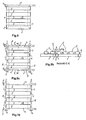
- a kit according to the invention for the construction of a floor covering has, as in FIG shown, three different types of covering elements.
- each includes supporting beams 1 on which Pedals 2 are fixed, which are spaced apart by joints 3.
- the number of supporting beams 1 and screeds 2 can be chosen arbitrarily, meaningfully however, as shown in Fig.3a, b, at least two support beams 1 are provided spaced parallel to each other.
- the first type of covering element shown on the far left in FIG. 1, is viewed in the plan square. His screeds 2 run parallel to the sides s.
- the second and third types are each considered in the form of a floor plan right-angled isosceles triangle.
- the cathets k1, k2 are the same long as the pages s of the first covering element type.
- the tread screeds 2 of the second and the third covering element type each run parallel to one of the two cathets k1, k2.
- the second and third types differ in that the Pedals 2 of the second type parallel to the first catheter k1 and pedals 2 of the third Type run parallel to the second catheter. If you lay a covering element of the second Type congruent over one of the third type, so the screeds 2 of the second Type perpendicular to those of the third type.
- a kit according to the invention has at least one piece of each type of covering element. In order to be able to produce large floor coverings, however, are usually several pieces of each type of covering element are provided.
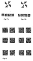
- the second and third covering element types (in the drawings with A and B referred to) to be assembled into different types of squares. Be there how 11a, a covering element of the second type A and a covering element of the third type B combined, the laying direction changes, i.e. the Direction of the step planks 2 and the joints 3.
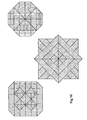
- 11a, b can be used as corner elements in friezes become (see Fig. 13) or larger squares with geometric structures be joined, see Fig. 12.
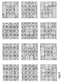
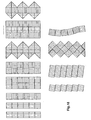
- Fig. 11-13 The basic installation patterns shown in Fig. 11-13 can be used for larger floor coverings can be used in any combination, are only exemplary in Figs. 14-18 some design options that can be realized with a kit according to the invention Floor coverings shown.
- both the joints 3 and the step boards 2 are aligned with each other or that at joints where the Direction of step of screeds 2 and joints 3 changes (see Fig.11a) to each other abutting, oblique end faces of the screeds 2 face each other over the entire surface and thus an aesthetic joint pattern is created, on the one hand, the Kick planks 2 of all covering elements of the same width y and are the other between these lying joints 3 all covering elements are of the same width.
- FIGS. 2a, b of the first covering element type there are four supporting beams 1 available, which are arranged to form a circumferential square frame. On such a circumferential frame is also in the embodiments shown in Fig.4a, b of the second and third covering element type.
- the type of attachment of the screeds 2 to the support beam 1 is not essential to the invention and can therefore also be chosen arbitrarily.
- the footboards 2 can, for example nailed to the support beam 1, screwed or glued to it.
- the footboards 2 can be chamfered on their four edges facing away from the supporting beam 1. This chamfer was only in Fig.2b and 3b or in Fig.2a on a screed 2 and in Fig.9b shown to keep the drawings clear.
- Beam 1 and screed 2 are preferably made of wood, but can also be made of other materials, especially metal, e.g. Aluminum. Furthermore is the formation of the support beam 1 from a first material (e.g. metal) with simultaneous It is possible to form the support planks 2 from a different material (e.g. wood).
- a first material e.g. metal
- a different material e.g. wood
- At least one spacer 5 is formed on at least one side surface 4 of the covering elements.
- This spacer 5 can in principle have any shape and size. So he can For example, be formed by a cube-shaped, dome-shaped or strip-shaped component attached to the relevant side surface 4 of the covering element (screwed, glued or. Like.) is. Another possibility would be to not use a spacer 5 screw fully screwed into the side surface 4 or not completely to form hammered nail. The number of spacers 5 per side surface 4 is 4 freely selectable.
- Each side surface 4 of the covering element is by belonging to step planks 2 and by Support beam 1 surfaces formed.
- the spacer 5 can optionally on one a screed 2 or on a surface belonging to a supporting beam 1 or simultaneously be fixed both on a support beam 1 and on a step board 2. Furthermore, it is possible, the spacer 5 in one piece with one of these covering element components to train.
- such a covering element is used in the manner according to the invention is provided on a side surface 4 with spacers 5, with this side surface 4 to the Side surface of another covering element created, so come the spacers 5 des covering element according to the invention on the side surface of the further covering element Investment.
- a joint 6 is thus formed between the two covering elements.
- each covering element spacer 5 is Attach side surfaces 4 of each covering element spacer 5 (see Fig. 6).
- all joints 3 between the screeds 2 of a covering element executed equally wide.
- This also means that between two adjacent covering elements resulting joints 6 have the same width as the joint elements 3 have, the spacers 5 are made with a width b, which is the joint width x corresponds.
- the spacers 5 can be placed so that when two covering elements are placed against one another the spacers 5 come to lie against each other, as shown in Fig.7 is. This is the case, for example, if two spacers 5 are located on one side surface 4 are provided and these are the same on both side surfaces 4 which are placed against one another Have distance a from the center symmetry axes 7 of the covering elements or the Spacer 5 on the two side surfaces 4 placed against each other by one Bar are formed, which overlap the central symmetry axes 7 of the covering elements are trained.
- the joint 6 formed between the two covering elements has a width, which corresponds to the sum of the widths b of the two spacers 5. So that between two Adjacent joints 6 resulting joints 6 the same in the local arrangement Width as the covering element internal joints 3, the spacers 5 with a width b, which corresponds to half the joint width x / 2.
- Such spacers 5 coming into contact with one another can be attached to several Side surfaces 4, for example analogous to Figure 6 on two abutting or also on all four side surfaces 4 may be provided.
- the spacers 5 are not formed by separate components, but by the support beams 1 already present:
- the support beams 1 are in the area of that side surface 4 of the covering element which a spacer 5 is to be formed, in front of the one (s) located there
- the side edge (s) of the step planks 2 are projecting (see Fig. 8 above).
- the size of this Projection is arbitrary or is preferred in the sense of the above statements the joint width x or half the joint width x / 2 accordingly.
- a booking 8 in in front of the side surface 4 protruding area of the support beam 1 a booking 8 be incorporated.
- this indentation 8 water, which on the support beam 1 reaches the floor under the floor covering. From this function the Indentation 8 shows that it is also smaller than shown in FIGS. 9a, 10 and 4c, d can be formed or that 1 several smaller indentations 8 per support beam can be provided.
Landscapes
- Engineering & Computer Science (AREA)
- Architecture (AREA)
- Civil Engineering (AREA)
- Structural Engineering (AREA)
- Floor Finish (AREA)
- Building Environments (AREA)
- Optical Couplings Of Light Guides (AREA)
- Paper (AREA)
- Mechanical Coupling Of Light Guides (AREA)
Abstract
Description
Claims (8)
- Bausatz zum Aufbau eines Bodenbelages umfassend mehrere Belags-Elemente, welche jeweils durch Tragbalken (1) und Trittbohlen (2) gebildet sind, wobei die Trittbohlen (2) auf den Tragbalken (1) durch Fugen (3) voneinander beabstandet festgelegt sind, dadurch gekennzeichnet, daß der Bausatz drei voneinander verschiedene Typen von Belags-Elementen aufweist, wobeider erste Typ im Grundriß betrachtet quadratisch ausgebildet ist,der zweite und der dritte Typ im Grundriß betrachtet jeweils in Gestalt eines rechtwinkelig-gleichschenkeligen Dreiecks ausgebildet ist, deren Katheten (k1,k2) gleich lang wie die Seiten (s) des ersten Typs sind, daßdie Trittbohlen (2) des ersten Typs parallel zu den Seiten (s),die Trittbohlen (2) des zweiten Typs parallel zur ersten Kathete (k1) unddie Trittbohlen (2) des dritten Typs parallel zur zweiten Kathete (k2) verlaufen.
- Bausatz nach Anspruch 1, dadurch gekennzeichnet, daß die Trittbohlen (2) sämtlicher Belags-Elemente gleiche Breite (y) und die Fugen (3) sämtlicher Belags-Elemente gleiche Breite (x) aufweisen.
- Bausatz nach Anspruch 1 oder 2, dadurch gekennzeichnet, daß die Tragbalken (1) in Gestalt eines umlaufenden Rahmens angeordnet sind.
- Bausatz nach Anspruch 1, 2 oder 3, dadurch gekennzeichnet, daß an zumindest einer Seitenfläche (4) jedes Belags-Elementes zumindest ein Abstandhalter (5) angeformt ist.
- Bausatz nach Anspruch 4, dadurch gekennzeichnet, daß bei gleich breiter Ausführung sämtlicher Fugen (3) der Belags-Elemente die Abstandhalter (5) eine der Fugenbreite (x) entsprechende Breite (b) aufweisen.
- Bausatz nach Anspruch 4, dadurch gekennzeichnet, daß bei gleich breiter Ausführung sämtlicher Fugen (3) der Belags-Elemente die Abstandhalter (5) eine der halben Fugenbreite (x/2) entsprechende Breite aufweisen.
- Bausatz nach Anspruch 4, 5 oder 6, dadurch gekennzeichnet, daß die Abstandhalter (5) durch die Tragbalken (1) selbst gebildet sind, indem diese vor die im Bereich zumindest einer Seitenfläche (4) des Belags-Elementes verlaufenden Seitenkanten der Trittbohlen (2) vorspringend angeordnet sind.
- Bausatz nach Anspruch 7, dadurch gekennzeichnet, daß die Tragbalken (1) im vor die Seitenfläche (4) des Belags-Elementes vorspringenden Bereich zumindest eine Einbuchtung (8) aufweisen.
Priority Applications (1)
| Application Number | Priority Date | Filing Date | Title |
|---|---|---|---|
| AT01890045T ATE281563T1 (de) | 2000-04-05 | 2001-02-22 | Bausatz zum aufbau eines bodenbelages |
Applications Claiming Priority (2)
| Application Number | Priority Date | Filing Date | Title |
|---|---|---|---|
| AT5772000 | 2000-04-05 | ||
| AT0057700A AT409990B (de) | 2000-04-05 | 2000-04-05 | Bausatz für einen gitterrost |
Publications (3)
| Publication Number | Publication Date |
|---|---|
| EP1143070A2 true EP1143070A2 (de) | 2001-10-10 |
| EP1143070A3 EP1143070A3 (de) | 2003-08-06 |
| EP1143070B1 EP1143070B1 (de) | 2004-11-03 |
Family
ID=3676870
Family Applications (1)
| Application Number | Title | Priority Date | Filing Date |
|---|---|---|---|
| EP01890045A Expired - Lifetime EP1143070B1 (de) | 2000-04-05 | 2001-02-22 | Bausatz zum Aufbau eines Bodenbelages |
Country Status (3)
| Country | Link |
|---|---|
| EP (1) | EP1143070B1 (de) |
| AT (2) | AT409990B (de) |
| DE (1) | DE50104347D1 (de) |
Cited By (1)
| Publication number | Priority date | Publication date | Assignee | Title |
|---|---|---|---|---|
| GB2415711A (en) * | 2004-06-28 | 2006-01-04 | Rowlinson Garden Products Ltd | Polygonal flooring modules |
Family Cites Families (7)
| Publication number | Priority date | Publication date | Assignee | Title |
|---|---|---|---|---|
| FR786307A (fr) * | 1934-12-15 | 1935-08-31 | Panneau ou carreau pour parquetage et son procédé de fabrication | |
| FR2238334A5 (en) * | 1973-07-17 | 1975-02-14 | Bourderie Odette | Decorative wall cladding - pattern is formed from square and triangular striped metal plates |
| DE2800560A1 (de) * | 1978-01-07 | 1979-07-12 | Schuez & Franke Betonwerk Gmbh | Betonplatte fuer die befestigung von wegen mit erhoehter wasserdurchlaessigkeit |
| US4282695A (en) * | 1979-07-18 | 1981-08-11 | Lew Hyok S | Self-interlocking grille |
| FR2473398B1 (fr) * | 1980-01-10 | 1987-10-09 | Roger Tallon | Panneaux trames a dimensions standardisees destines a la realisation d'amenagements et/ou de mobiliers, systemes de differents types de tels panneaux a dimensions standards de base correlees, et procede particulier d'elaboration de tels panneaux a partir de bois massif |
| ATE32365T1 (de) * | 1983-12-09 | 1988-02-15 | Thierry Martin | Zusammengesetzte deckplatte mit integrierter schalldaemmung und waermeschutz fuer fussboden-, wand- und deckenverkleidungen. |
| FR2729986A1 (fr) * | 1995-01-27 | 1996-08-02 | France Bois Impregnes Sa | Caillebotis notamment pour la construction de planchers |
-
2000
- 2000-04-05 AT AT0057700A patent/AT409990B/de not_active IP Right Cessation
-
2001
- 2001-02-22 DE DE50104347T patent/DE50104347D1/de not_active Expired - Fee Related
- 2001-02-22 EP EP01890045A patent/EP1143070B1/de not_active Expired - Lifetime
- 2001-02-22 AT AT01890045T patent/ATE281563T1/de not_active IP Right Cessation
Cited By (2)
| Publication number | Priority date | Publication date | Assignee | Title |
|---|---|---|---|---|
| GB2415711A (en) * | 2004-06-28 | 2006-01-04 | Rowlinson Garden Products Ltd | Polygonal flooring modules |
| GB2415711B (en) * | 2004-06-28 | 2009-01-28 | Rowlinson Garden Products Ltd | Flooring |
Also Published As
| Publication number | Publication date |
|---|---|
| ATE281563T1 (de) | 2004-11-15 |
| DE50104347D1 (de) | 2004-12-09 |
| EP1143070B1 (de) | 2004-11-03 |
| EP1143070A3 (de) | 2003-08-06 |
| AT409990B (de) | 2002-12-27 |
| ATA5772000A (de) | 2002-05-15 |
Similar Documents
| Publication | Publication Date | Title |
|---|---|---|
| DE10239146B4 (de) | Paneel | |
| DE2615891C2 (de) | ||
| DE8401923U1 (de) | Einrichtung zur verkleidung von flaechen mit flaechenelementen | |
| EP0074338B1 (de) | Plattenförmiges Verkleidungselement | |
| DE4239051C2 (de) | Gebäudewandverkleidung | |
| DE8812547U1 (de) | Winkelschiene für die Verlegung von Fliesen oder Platten | |
| CH718836A2 (de) | Modularer Terrassenaufbau. | |
| EP1143070B1 (de) | Bausatz zum Aufbau eines Bodenbelages | |
| DE3241424C2 (de) | Verbindungseinrichtung | |
| AT1025U1 (de) | Bauelement sowie damit hergestellte wandverkleidung | |
| EP1022407A2 (de) | Fussboden aus Holz oder einem Holzwerkstoff | |
| DE19640128A1 (de) | Bodenbelag-Element | |
| DE2825563A1 (de) | Bauholz | |
| EP0696668B1 (de) | Vorrichtung zum Errichten einer Schalung für die Unterseite des Treppenkörpers einer Gebäudetreppe | |
| DE9214696U1 (de) | Armierungsgewebe für Putze, Dämmsysteme o.dgl. | |
| DE2440289B2 (de) | Bodenbelag | |
| EP0621378B1 (de) | Versteifungsvorrichtung für eine Montagewand | |
| DE3204985A1 (de) | Fussboden mit bodenheizung sowie verfahren zum verlegen einer bodenheizung | |
| DE2848432A1 (de) | Decken- oder wandverkleidung | |
| DE3116152C2 (de) | Deckenabschluß aus Holz zur Erzeugung von doppelten Schattenfugen im Randbereich | |
| DE8712398U1 (de) | Aus vorgefertigten Betonteilen bestehender Bausatz zur Erstellung von Gebäuden | |
| DE3689994T2 (de) | Lamelliertes bauelement. | |
| AT528453A1 (de) | Element für eine modulare Treppenwange | |
| EP2884023A1 (de) | Verlegeelement mit Verbindungsmitteln | |
| DE19652877A1 (de) | Eckleiste, insbesondere zur dauerhaften Ausbildung von Putzkanten oder dergleichen |
Legal Events
| Date | Code | Title | Description |
|---|---|---|---|
| PUAI | Public reference made under article 153(3) epc to a published international application that has entered the european phase |
Free format text: ORIGINAL CODE: 0009012 |
|
| AK | Designated contracting states |
Kind code of ref document: A2 Designated state(s): AT BE CH CY DE DK ES FI FR GB GR IE IT LI LU MC NL PT SE TR |
|
| AX | Request for extension of the european patent |
Free format text: AL;LT;LV;MK;RO;SI |
|
| PUAL | Search report despatched |
Free format text: ORIGINAL CODE: 0009013 |
|
| AK | Designated contracting states |
Designated state(s): AT BE CH CY DE DK ES FI FR GB GR IE IT LI LU MC NL PT SE TR |
|
| AX | Request for extension of the european patent |
Extension state: AL LT LV MK RO SI |
|
| 17P | Request for examination filed |
Effective date: 20040206 |
|
| GRAP | Despatch of communication of intention to grant a patent |
Free format text: ORIGINAL CODE: EPIDOSNIGR1 |
|
| AKX | Designation fees paid |
Designated state(s): AT DE |
|
| GRAS | Grant fee paid |
Free format text: ORIGINAL CODE: EPIDOSNIGR3 |
|
| GRAA | (expected) grant |
Free format text: ORIGINAL CODE: 0009210 |
|
| AK | Designated contracting states |
Kind code of ref document: B1 Designated state(s): AT DE |
|
| REF | Corresponds to: |
Ref document number: 50104347 Country of ref document: DE Date of ref document: 20041209 Kind code of ref document: P |
|
| REG | Reference to a national code |
Ref country code: IE Ref legal event code: FG4D Free format text: GERMAN |
|
| PG25 | Lapsed in a contracting state [announced via postgrant information from national office to epo] |
Ref country code: AT Free format text: LAPSE BECAUSE OF NON-PAYMENT OF DUE FEES Effective date: 20050222 |
|
| REG | Reference to a national code |
Ref country code: IE Ref legal event code: FD4D |
|
| PLBE | No opposition filed within time limit |
Free format text: ORIGINAL CODE: 0009261 |
|
| STAA | Information on the status of an ep patent application or granted ep patent |
Free format text: STATUS: NO OPPOSITION FILED WITHIN TIME LIMIT |
|
| 26N | No opposition filed |
Effective date: 20050804 |
|
| PGFP | Annual fee paid to national office [announced via postgrant information from national office to epo] |
Ref country code: DE Payment date: 20060425 Year of fee payment: 6 |
|
| PG25 | Lapsed in a contracting state [announced via postgrant information from national office to epo] |
Ref country code: DE Free format text: LAPSE BECAUSE OF NON-PAYMENT OF DUE FEES Effective date: 20070901 |