EP1143073A2 - Methode und Vorrichtung zur Steuerung des Innendrucks eines aufblasbaren Dammes - Google Patents
Methode und Vorrichtung zur Steuerung des Innendrucks eines aufblasbaren Dammes Download PDFInfo
- Publication number
- EP1143073A2 EP1143073A2 EP01302881A EP01302881A EP1143073A2 EP 1143073 A2 EP1143073 A2 EP 1143073A2 EP 01302881 A EP01302881 A EP 01302881A EP 01302881 A EP01302881 A EP 01302881A EP 1143073 A2 EP1143073 A2 EP 1143073A2
- Authority
- EP
- European Patent Office
- Prior art keywords
- bag body
- water
- internal pressure
- flexible
- gas
- Prior art date
- Legal status (The legal status is an assumption and is not a legal conclusion. Google has not performed a legal analysis and makes no representation as to the accuracy of the status listed.)
- Ceased
Links
Images


Classifications
-
- E—FIXED CONSTRUCTIONS
- E02—HYDRAULIC ENGINEERING; FOUNDATIONS; SOIL SHIFTING
- E02B—HYDRAULIC ENGINEERING
- E02B7/00—Barrages or weirs; Layout, construction, methods of, or devices for, making same
- E02B7/005—Deformable barrages or barrages consisting of permanently deformable elements, e.g. inflatable, with flexible walls
Definitions
- the present invention relates to an internal pressure regulating system for a flexible bag body used for an inflatable and collapsible dam, particularly, to an internal pressure regulating system for a flexible bag body, in which an internal pressure of a flexible bag body can be automatically regulated, by a simple structure, in accordance with a level of a water area in which the flexible bag body is provided.
- the present invention also relates to a flexible membrane dam using the above-described system, and a method for regulating an internal pressure of the flexible membrane dam.
- a flexible membrane dam/weir has been widely used, wherein a flexible bag body is inflated by supplying air therein and is deflated by discharging air therefrom.
- a flexible membrane dam is structured in such a manner that a flexible bag body having a heightwise dimension corresponding to an operating condition is in advance prepared, and placed on the ground near a watercourse such as a river to form a collapsible dam.
- Figs. 4A and 4B show such conventional internal pressure regulating systems as described above.
- Fig. 4A is a cross sectional view when a water sealing pipe is used
- Fig. 4B is a cross sectional view when a U-tube is used.
- the water sealing pipe is structured in such a manner that an open end 12 of a branch pipe 11 into which gas within a flexible bag body (not shown) is introduced, is submerged in the water 13.
- gas within the flexible bag body pushes out water within the branch pipe 11 and leaks out so that the internal pressure of the flexible bag body decreases.
- An internal pressure regulating system using a U-tube is structured in such a manner that water 15 is stored in a U-tube 14 into which gas within the flexible bag body is introduced, and when an internal pressure of the bag body increases, gas within the bag body pushes up the water 15 within the U-tube 14 so as to regulate the internal pressure and a water head pressure. Accordingly, the capacity of the flexible bag body increases by an amount of water pushed up, and the internal pressure decreases. Further, a back pressure regulating valve is provided in the flexible bag body, and when the internal pressure becomes a predetermined value or higher, the valve is brought into an open state.
- a first aspect of the present invention is an internal pressure regulating system for a flexible bag body, in which gas within a flexible bag body is discharged when the flexible bag body used for a collapsible dam is excessively pressurized, the system comprising a flexible bag body which can be inflated with a gas for damming the body of water into upstream and downstream regions, and a pipe body having opposite first and second ends, wherein the bag body includes an exhaust opening for exhausting the gas, the first end of the pipe body is connected to the exhaust opening in the bag body, and the second end of the pipe body is introduced into the upstream region of the body of water.
- the internal pressure of the bag body can be automatically adjusted so as to correspond to the upstream water level.
- an internal pressure regulating system for a flexible bag body is provided in which at least one non-return valve is provided in the pipe body to prevent water from flowing from the upstream side into the bag body.
- the open end of the pipe body is submerged in water, from the surface of the water at the upstream side of the water area in which the flexible bag body is placed, at a position which is lower than or equal to a reference level at which the flexible bag body is installed.
- the exhaust opening of the bag body is provided at a position separated from an air supplying opening at which gas from an air supplying device is supplied into the bag body, particularly, the exhaust opening is provided at one end of the bag body.
- the air supplying opening is provided at the other end of the bag body.
- the exhaust opening is provided at an upper side of a level of drain within the bag body.
- a second aspect of the present invention is a flexible membrane dam including the above-described internal pressure regulating system, in which the flexible bag body can be inflated by supplying gas therein and can be deflated by discharging gas therefrom.
- a third aspect of the present invention is a method for regulating an internal pressure in a flexible membrane dam, which includes continuously or intermittently supplying gas into a flexible bag body.
- the internal pressure of the bag body is automatically adjusted so as to correspond to the upstream water level. That is, when an internal pressure higher than or equal to the upstream water level is generated in the bag body, air is blown off from the internal pressure regulating system. Further, in an overflow state, the internal pressure is adjusted so as to correspond to an overflow level. In a non-overflow state, air pressure is adjusted to become an internal pressure corresponding to the upstream water level, and excessive increase in the pressure caused by exposure to sunlight or the like is prevented. As described above, in the present invention, a mechanical structure in which the internal pressure can be safely adjusted in accordance with the upstream water level, is provided without using an electrical structure which may cause a failure.
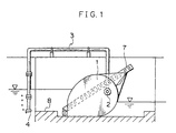
- Fig. 1 is a cross sectional view which shows a flexible membrane dam using an internal pressure regulating system according to a first embodiment of the present invention.
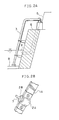
- Figs. 2A and 2B are diagrams each showing a state in which a pipe body of the internal pressure regulating system of the present invention is installed.
- Fig. 3 is a cross sectional view which shows a flexible membrane dam using an internal pressure regulating system according to a second embodiment of the present invention.
- Figs. 4A and 4B are diagrams showing conventional internal pressure regulating systems.
- An internal pressure regulating system for a flexible bag body is comprised of a flexible bag body in which gas can be filled, and a pipe body extending from an exhaust opening formed in the bag body and having an open end.
- the bag body may have any structure which allows filling of gas therein and which is able to resist fluid pressure of a river or the like.
- the most preferable embodiment of the bag body is a structure in which an air chamber is formed by providing a non-bonded layer within a plate-like rubber reinforced by nylon fiber. When gas is discharged, the structure is made into a plate-like configuration.
- the open end of the pipe body is introduced into the water at an upstream side of a water area in which the flexible bag body is provided.
- gas filled in the flexible bag body is sealed by water flowing into the open end.
- the amount of water flowing from the open end varies depending on a water level at the upstream side of the water area in which the flexible bag body is provided. That is, in the internal pressure regulating system of the present invention, when it is necessary to increase the internal pressure for the reason that the water level at the upstream side rises so that a fluid pressure acting on the flexible bag body increases, a hydraulic pressure at the side of the open end also increases accompanied with rising of the water level. Therefore, the internal pressure and the hydraulic pressure are constantly balanced.
- the internal pressure regulating system of the present invention utilizes the hydraulic pressure at the upstream side of the water area in which the flexible bag body is provided. Therefore, the internal pressure of the bag body varies in accordance with the water level at the upstream side so that a proper internal pressure can constantly be set automatically. As a result, it is not necessary that an exhaust pressure setting device of internal gas be additionally provided. Only when the internal pressure of the bag body excessively increases, blow-off of gas from the open end of the pipe body occurs.
- a non-return valve may be provided in the pipe body for a case in which the level of the water area in which the flexible bag body is placed, may vary.
- a method for introducing the open end of the pipe body into the water is not particularly limited as long as the open end of the pipe body is introduced at the upstream side of the water area in which the flexible bag body is placed.
- the pipe body may be introduced from the bottom of the water or from the surface of the water.
- the open end of the pipe body is submerged from the surface of the water.
- a degree at which the pipe body is sunk under water, is set so that the open end is located at the same level as a reference level at which the flexible bag body is placed, or lower.
- an air supplying device is connected to the flexible bag body and air is supplied from an air supplying opening into the bag body. Accordingly, at the time of air supply, the internal pressure in the vicinity of the air supplying opening becomes higher, and pressure distribution of the bag body is not necessarily uniform. Further, it is also necessary to prevent drain from coming into the pipe body. Accordingly, a structure is most preferable in which an exhaust opening of the bag body is provided at a position separated from the air supplying opening and above the drain in the bag body, particularly, at an upper side of one end of the bag body, and the air supplying opening is provided at the other end of the bag body.
- the above-described internal pressure regulating system is used for a flexible membrane dam which can be inflated by supplying gas therein and can be deflated by discharging gas therefrom. Namely, it is necessary that the flexible membrane dam has a predetermined heightwise dimension and is laid flat by a proper overflow. For this reason, excessive increase in the pressure of the flexible bag body used for the flexible membrane dam should be prevented. Accordingly, excessive increase in the pressure, which is caused by an abnormal condition of an air supplying device or exposure to sunlight in a state in which the bag body is erected when the water level is low, is controlled by the internal pressure regulating system.
- the internal pressure of the flexible membrane dam is automatically adjusted so as to basically correspond to an upstream water level. That is, when the internal pressure in the flexible bag body relatively increases due to increase in the internal pressure caused by an abnormal condition of an air supplying device or exposure to sunlight, or decrease in the upstream water level, gas within the bag body blows off via the pipe body until the internal pressure in the bag body is balanced with a pressure corresponding to the upstream water level. Further, in an overflow state, the internal pressure is adjusted so as to correspond to the overflow level. Accordingly, the flexible membrane dam is maintained with a predetermined heightwise dimension and can be used safely and continuously.
- an air supplying device equipped with a timer is adapted to intermittently supply air in such a manner as to operate for five minutes at intervals of 24 hours. So long as air is intermittently supplied, when the internal pressure in the flexible bag body is relatively high, gas within the bag body blows off via the pipe body. Further, when the internal pressure of the flexible bag body is relatively low, it increases to a balanced pressure intensity. Thus, a necessary amount of air is constantly maintained.
- a small-size blower for example, an engine type or solar-cell type blower of 0.3 kw or thereabouts
- the air supplying device can be manually operated when necessary.
- Fig. 1 is a cross sectional view showing a flexible membrane dam according to a first embodiment which is the above-described most preferable embodiment of the present invention.
- the flexible membrane dam is provided in such a manner that a flexible bag body 1 into which gas can be filled, can be inflated by supplying gas therein and can be deflated by discharging gas therefrom.
- the heightwise dimension of the dam is determined by adjusting a state in which the bag body is inflated, based on an amount of gas supplied into the bag body 1 (that is, the internal pressure of the bag body 1).
- the flexible bag body 1 has a structure in which an air chamber is formed by providing a non-bonded layer within a plate-like rubber reinforced by nylon fiber. When gas is discharged from the bag body, the structure is made into a plate-like configuration.
- An exhaust opening 2 is formed in the bag body 1, and a pipe body 3 (50A) having an open end 4 extends from the exhaust opening 2.
- the exhaust opening 2 is provided at the upper side of an end of the bag body 1 at a side opposite to the side at which an air supplying opening for supplying gas from an air supplying device (not shown) into the bag body 1, is provided.
- FIG. 2A A method for installation of the pipe body 3 is shown in Figs. 2A and 2B.
- the pipe body 3 is disposed from a portion in which the exhaust opening 2 is formed, over a slope-face toward a crest by placing concrete to a surface 5 to which arrangement of bar is exposed.
- pulling support members are fixed by round steel or the like using arrangement of bar, and a concrete application portion is covered with concrete (a concrete portion 6).
- the anchor bolt 7 is cut off, and a cutting portion of the anchor bolt 7 and the arrangement of bar are welded and fixed together using round steel or the like.
- a pair of metal fittings 2A each having a substantially semicircular configuration, are formed by being mounted at a portion of a mounting metal fitting 1A of the bag body.
- a substantially diamond-shaped rubber member 2B with the pipe body 3 passing therethrough is interposed between the metal fittings 2A.
- the pipe body 3 extending toward the upstream side, extends along the slope face to the same level as a reference surface 8 at which a dam is installed. As shown in Figs. 1 and 2, the open end 4 of the pipe body 3 is submerged from the surface of the water at the upstream side of the water area in which the flexible bag body is placed, and is located at a position which is the same level as the reference surface 8 at which the flexible bag body 1 is installed, or lower.
- the pipe body 3 may be a rubber hose in a state of emergency.
- Fig. 3 is a cross sectional view showing a flexible membrane dam according to a second embodiment of the present invention.
- the exhaust opening 2 is formed on a lower surface of the flexible bag body 1 and the pipe body 3 extends in the ground with an open end thereof being located in a water bottom portion.
- drain within the flexible bag body 1 can be discharged simultaneously.
- the pipe body 3 includes a non-return valve 9 which prevents water from counterflowing into the bag body 1.
Landscapes
- Engineering & Computer Science (AREA)
- Structural Engineering (AREA)
- General Engineering & Computer Science (AREA)
- Mechanical Engineering (AREA)
- Civil Engineering (AREA)
- Barrages (AREA)
Applications Claiming Priority (2)
| Application Number | Priority Date | Filing Date | Title |
|---|---|---|---|
| JP2000087899 | 2000-03-28 | ||
| JP2000087899A JP2001271328A (ja) | 2000-03-28 | 2000-03-28 | 可撓性袋体の内圧調整装置、それを用いた可撓性膜堰及びその内圧調整方法 |
Publications (2)
| Publication Number | Publication Date |
|---|---|
| EP1143073A2 true EP1143073A2 (de) | 2001-10-10 |
| EP1143073A3 EP1143073A3 (de) | 2003-03-05 |
Family
ID=18603845
Family Applications (1)
| Application Number | Title | Priority Date | Filing Date |
|---|---|---|---|
| EP01302881A Ceased EP1143073A3 (de) | 2000-03-28 | 2001-03-28 | Methode und Vorrichtung zur Steuerung des Innendrucks eines aufblasbaren Dammes |
Country Status (4)
| Country | Link |
|---|---|
| US (1) | US6467999B2 (de) |
| EP (1) | EP1143073A3 (de) |
| JP (1) | JP2001271328A (de) |
| AU (1) | AU783567B2 (de) |
Cited By (3)
| Publication number | Priority date | Publication date | Assignee | Title |
|---|---|---|---|---|
| EP1415049A4 (de) * | 2001-07-09 | 2005-01-12 | Henry K Obermeyer | Wehr zur regelung der wasserstandshöhe und stellglied dafür |
| CN104535249A (zh) * | 2014-12-04 | 2015-04-22 | 熊达煜 | 一种自动控制水坝水压力检测装置及其监测方法 |
| CN113042981A (zh) * | 2021-04-21 | 2021-06-29 | 中国水利水电第十工程局有限公司 | 端柱结构组拼工装、刚性止水人字闸门制造方法 |
Families Citing this family (7)
| Publication number | Priority date | Publication date | Assignee | Title |
|---|---|---|---|---|
| US10697143B2 (en) | 2016-12-22 | 2020-06-30 | HTE Engineering LLC | Inflatable dam and method thereof |
| US10273645B2 (en) | 2016-12-22 | 2019-04-30 | HTE Engineering LLC | Inflatable dam and method thereof |
| CN107489169B (zh) * | 2017-08-30 | 2023-05-09 | 中交公路规划设计院有限公司 | 水囊式调压装置及调压方法 |
| CN109811722B (zh) * | 2019-01-24 | 2020-09-15 | 东阳市天杨建筑工程设计有限公司 | 水利河道护坡 |
| CN110485380A (zh) * | 2019-09-06 | 2019-11-22 | 黄芳 | 一种河道生态治理用气囊调节坝 |
| CN113863220A (zh) * | 2021-09-29 | 2021-12-31 | 中交第四航务工程局有限公司 | 一种水利工程边坡防护装置 |
| CN116265784A (zh) * | 2022-11-09 | 2023-06-20 | 河北省交通规划设计研究院有限公司 | 一种隧道气液联动平衡限压排水装置 |
Family Cites Families (21)
| Publication number | Priority date | Publication date | Assignee | Title |
|---|---|---|---|---|
| US1421857A (en) * | 1920-05-27 | 1922-07-04 | Store Johan | Method of constructing subaqueous concrete structures |
| US3173269A (en) * | 1961-10-13 | 1965-03-16 | Norman M Imbertson | Collapsible dam |
| GB1448233A (en) * | 1972-10-18 | 1976-09-02 | Pnejmatiques Caoutchouc Manufa | Inflatable barriers |
| US4330224A (en) * | 1979-03-20 | 1982-05-18 | Bridgestone Tire Company Limited | Collapsible rubber dam installation |
| US4498810A (en) * | 1980-03-06 | 1985-02-12 | Bridgestone Tire Company Limited | Collapsible rubber dam |
| JPS5837448B2 (ja) * | 1981-03-19 | 1983-08-16 | 住友電気工業株式会社 | 可撓性膜製起伏堰 |
| JPS57190816A (en) * | 1981-05-20 | 1982-11-24 | Bridgestone Corp | Device for preventing production of excessive pressure in flexible film dam |
| JPS5941506A (ja) * | 1982-08-31 | 1984-03-07 | Hokoku Kogyo Kk | 堰の起伏装置 |
| JPS6030710A (ja) * | 1983-07-27 | 1985-02-16 | Nippon Koei Kk | ゴム堰の堰高検出装置 |
| JPS6062314A (ja) * | 1983-09-16 | 1985-04-10 | Bando Chem Ind Ltd | ゴム堰 |
| JPS60238510A (ja) * | 1984-05-11 | 1985-11-27 | Bridgestone Corp | 可撓性膜堰における水位制御方法 |
| JPS6149014A (ja) * | 1984-08-18 | 1986-03-10 | Hokoku Kogyo Kk | 袋状堰の吐水装置 |
| JPS61169512A (ja) * | 1985-01-19 | 1986-07-31 | Sumitomo Electric Ind Ltd | 空気膨張式可撓性膜製起伏堰 |
| JP2515515B2 (ja) * | 1986-10-02 | 1996-07-10 | 株式会社ブリヂストン | ゴム堰 |
| JP2688896B2 (ja) * | 1987-02-03 | 1997-12-10 | 株式会社ブリヂストン | 損傷防護可撓性膜堰 |
| US5186391A (en) * | 1989-10-06 | 1993-02-16 | Wallace Roueche | Portable sprayer |
| DE3934530C2 (de) * | 1989-10-17 | 1994-07-14 | Floecksmuehle Energietechnik G | Hydrostatische Wehreinrichtung |
| US5127766A (en) | 1990-10-30 | 1992-07-07 | Sumotomo Electric Industries, Ltd. | Apparatus and method for controlling the inner pressure of an air bag in an air inflation/deflation weir made of flexible film |
| JP2944795B2 (ja) * | 1991-07-22 | 1999-09-06 | 株式会社ブリヂストン | 可撓性膜堰の取付構造 |
| JP3792873B2 (ja) * | 1998-01-13 | 2006-07-05 | 株式会社ブリヂストン | ラバーダム |
| US6250977B1 (en) * | 1999-03-26 | 2001-06-26 | Dwight Ness | Compressed-air-powered immersible prime mover providing impulse propulsion to pool cleaners, trolling boats, and scuba divers |
-
2000
- 2000-03-28 JP JP2000087899A patent/JP2001271328A/ja not_active Withdrawn
-
2001
- 2001-03-23 US US09/814,805 patent/US6467999B2/en not_active Expired - Lifetime
- 2001-03-26 AU AU31312/01A patent/AU783567B2/en not_active Ceased
- 2001-03-28 EP EP01302881A patent/EP1143073A3/de not_active Ceased
Cited By (8)
| Publication number | Priority date | Publication date | Assignee | Title |
|---|---|---|---|---|
| EP1415049A4 (de) * | 2001-07-09 | 2005-01-12 | Henry K Obermeyer | Wehr zur regelung der wasserstandshöhe und stellglied dafür |
| US7114879B2 (en) | 2001-07-09 | 2006-10-03 | Henry K. Obermeyer | Water control gate and actuator therefore |
| US8511937B2 (en) | 2001-07-09 | 2013-08-20 | Henry K. Obermeyer | Water control apparatus |
| US9028170B2 (en) | 2001-07-09 | 2015-05-12 | Henry K. Obermeyer | Water control apparatus |
| US9765495B2 (en) | 2001-07-09 | 2017-09-19 | Henry K. Obermeyer | Water control apparatus |
| US10370813B2 (en) | 2001-07-09 | 2019-08-06 | Henry K. Obermeyer | Water control apparatus |
| CN104535249A (zh) * | 2014-12-04 | 2015-04-22 | 熊达煜 | 一种自动控制水坝水压力检测装置及其监测方法 |
| CN113042981A (zh) * | 2021-04-21 | 2021-06-29 | 中国水利水电第十工程局有限公司 | 端柱结构组拼工装、刚性止水人字闸门制造方法 |
Also Published As
| Publication number | Publication date |
|---|---|
| US6467999B2 (en) | 2002-10-22 |
| JP2001271328A (ja) | 2001-10-05 |
| EP1143073A3 (de) | 2003-03-05 |
| AU3131201A (en) | 2001-10-04 |
| US20010028826A1 (en) | 2001-10-11 |
| AU783567B2 (en) | 2005-11-10 |
Similar Documents
| Publication | Publication Date | Title |
|---|---|---|
| US6467999B2 (en) | Internal pressure regulating system for flexible bag body, flexible membrane dam using the same, and method for regulating internal pressure in the flexible membrane dam | |
| CA1058822A (en) | Floating cover assembly | |
| US4330224A (en) | Collapsible rubber dam installation | |
| US4498810A (en) | Collapsible rubber dam | |
| KR20100089375A (ko) | 수위조절이 용이한 고무댐 및 그 가동방법 | |
| AU2024219924A1 (en) | Diffuser for aeration of a fluid | |
| KR900006382B1 (ko) | 공기팽창식 가요성 막으로된 기복 가능한 둑 | |
| JP2024144050A (ja) | 水防構造及び水防方法 | |
| GB2077825A (en) | Collapsible Rubber Dam | |
| Binnie et al. | INFLATABLE WEIR USED DURING CONSTRUCTION OF MANGLA DAM. | |
| JPS5948244B2 (ja) | 多連式可撓性膜製起伏堰 | |
| JPH0430012A (ja) | 流量調整可撓性膜堰 | |
| JPS5930040Y2 (ja) | ゴム堰 | |
| KR860000325B1 (ko) | 절첩식 고무댐 | |
| KR200206348Y1 (ko) | 고무댐의 공기압 자동 조절장치 | |
| KR910000225Y1 (ko) | 유체 팽창식 고무댐 | |
| KR200224488Y1 (ko) | 고무댐의 공기 배출장치 | |
| EP0054289A1 (de) | Bewegliches Wehr | |
| CN219137578U (zh) | 一种橡胶贮水坝 | |
| JPH1060868A (ja) | 可撓性膜堰 | |
| KR200367430Y1 (ko) | 단계적 수위조절이 용이한 고무댐 | |
| JP2576890B2 (ja) | 可撓性膜堰 | |
| JPS6352232B2 (de) | ||
| JPS6220493Y2 (de) | ||
| JPS6118604B2 (de) |
Legal Events
| Date | Code | Title | Description |
|---|---|---|---|
| PUAI | Public reference made under article 153(3) epc to a published international application that has entered the european phase |
Free format text: ORIGINAL CODE: 0009012 |
|
| AK | Designated contracting states |
Kind code of ref document: A2 Designated state(s): AT BE CH CY DE DK ES FI FR GB GR IE IT LI LU MC NL PT SE TR |
|
| AX | Request for extension of the european patent |
Free format text: AL;LT;LV;MK;RO;SI |
|
| PUAL | Search report despatched |
Free format text: ORIGINAL CODE: 0009013 |
|
| AK | Designated contracting states |
Kind code of ref document: A3 Designated state(s): AT BE CH CY DE DK ES FI FR GB GR IE IT LI LU MC NL PT SE TR Designated state(s): AT BE CH CY DE DK ES FI FR GB GR IE IT LI LU MC NL PT SE TR |
|
| AX | Request for extension of the european patent |
Extension state: AL LT LV MK RO SI |
|
| RIC1 | Information provided on ipc code assigned before grant |
Ipc: 7E 02B 7/00 B Ipc: 7E 02B 7/20 A |
|
| 17P | Request for examination filed |
Effective date: 20030704 |
|
| AKX | Designation fees paid |
Designated state(s): DE ES NL |
|
| STAA | Information on the status of an ep patent application or granted ep patent |
Free format text: STATUS: THE APPLICATION HAS BEEN REFUSED |
|
| 18R | Application refused |
Effective date: 20100618 |