EP1143143A2 - Piston de compresseur et son procédé de fabrication - Google Patents
Piston de compresseur et son procédé de fabrication Download PDFInfo
- Publication number
- EP1143143A2 EP1143143A2 EP01108328A EP01108328A EP1143143A2 EP 1143143 A2 EP1143143 A2 EP 1143143A2 EP 01108328 A EP01108328 A EP 01108328A EP 01108328 A EP01108328 A EP 01108328A EP 1143143 A2 EP1143143 A2 EP 1143143A2
- Authority
- EP
- European Patent Office
- Prior art keywords
- face
- piston
- protrusion
- end wall
- inner end
- Prior art date
- Legal status (The legal status is an assumption and is not a legal conclusion. Google has not performed a legal analysis and makes no representation as to the accuracy of the status listed.)
- Withdrawn
Links
- 238000000034 method Methods 0.000 title claims description 9
- 230000003014 reinforcing effect Effects 0.000 claims abstract description 46
- 238000013459 approach Methods 0.000 claims abstract description 7
- 229910052751 metal Inorganic materials 0.000 claims description 12
- 239000002184 metal Substances 0.000 claims description 12
- 230000015572 biosynthetic process Effects 0.000 claims description 4
- 238000004519 manufacturing process Methods 0.000 claims description 3
- 239000003507 refrigerant Substances 0.000 description 12
- 238000006073 displacement reaction Methods 0.000 description 7
- 238000005520 cutting process Methods 0.000 description 5
- 230000033001 locomotion Effects 0.000 description 5
- 229910052782 aluminium Inorganic materials 0.000 description 2
- XAGFODPZIPBFFR-UHFFFAOYSA-N aluminium Chemical compound [Al] XAGFODPZIPBFFR-UHFFFAOYSA-N 0.000 description 2
- 238000005266 casting Methods 0.000 description 2
- 238000004512 die casting Methods 0.000 description 2
- 239000000463 material Substances 0.000 description 2
- 238000000465 moulding Methods 0.000 description 2
- 239000000853 adhesive Substances 0.000 description 1
- 230000001070 adhesive effect Effects 0.000 description 1
- 230000000694 effects Effects 0.000 description 1
- 230000002093 peripheral effect Effects 0.000 description 1
- 238000007493 shaping process Methods 0.000 description 1
- 238000007711 solidification Methods 0.000 description 1
- 230000008023 solidification Effects 0.000 description 1
Images






Classifications
-
- F—MECHANICAL ENGINEERING; LIGHTING; HEATING; WEAPONS; BLASTING
- F04—POSITIVE - DISPLACEMENT MACHINES FOR LIQUIDS; PUMPS FOR LIQUIDS OR ELASTIC FLUIDS
- F04B—POSITIVE-DISPLACEMENT MACHINES FOR LIQUIDS; PUMPS
- F04B27/00—Multi-cylinder pumps specially adapted for elastic fluids and characterised by number or arrangement of cylinders
- F04B27/08—Multi-cylinder pumps specially adapted for elastic fluids and characterised by number or arrangement of cylinders having cylinders coaxial with, or parallel or inclined to, main shaft axis
- F04B27/0873—Component parts, e.g. sealings; Manufacturing or assembly thereof
- F04B27/0878—Pistons
-
- F—MECHANICAL ENGINEERING; LIGHTING; HEATING; WEAPONS; BLASTING
- F04—POSITIVE - DISPLACEMENT MACHINES FOR LIQUIDS; PUMPS FOR LIQUIDS OR ELASTIC FLUIDS
- F04B—POSITIVE-DISPLACEMENT MACHINES FOR LIQUIDS; PUMPS
- F04B27/00—Multi-cylinder pumps specially adapted for elastic fluids and characterised by number or arrangement of cylinders
- F04B27/08—Multi-cylinder pumps specially adapted for elastic fluids and characterised by number or arrangement of cylinders having cylinders coaxial with, or parallel or inclined to, main shaft axis
Definitions
- the present invention relates to compressor pistons, and more specifically, to hollow pistons and a process for producing hollow pistons.
- a typical variable displacement compressor is provided with a tilting swash plate, which is located in a crank chamber, and pistons are connected to the swash plate.
- the swash plate converts rotational motion of a drive shaft into reciprocating motions of the pistons.
- the inclination angle of the swash plate varies depending on the pressure in the crank chamber. The inclination angle of the swash plate governs the piston stroke and displacement of the compressor.
- Japanese Unexamined Patent Publication Nos. Hei 10-281065, Hei 11- 294320 and Hei 11-107912 each disclose a hollow piston to be used in a compressor. Hollow pistons are light and have small inertia forces. Therefore, if hollow pistons are used in a variable displacement compressor, they minimize their influence on the swash plate's movement of changing the inclination angle, so that the displacement of the compressor can be changed with good response.
- the end wall of the piston head receives the high pressure of the compressed refrigerant gas.
- a typical piston has a flat head end wall, so that if the head end wall is relatively thin, it cannot withstand the pressure.
- the piston disclosed in Japanese Unexamined Patent Publication No. Hei 10-281065, which is referred to above, has a recess at the center of the head end wall.
- a center pin of a machine tool is fitted in the reference recess.
- the machine tool cuts the periphery of the piston while the piston rotates around the a rotational axis.
- the recess reduces the strength of the head end wall of the piston.
- the thickness of the wall must be increased. However, this increases the weight of the piston.
- the present invention provides a hollow piston used in a compressor.
- the piston has an end wall that receives the pressure of a cylinder bore of the compressor.
- the end wall has a substantially flat outer end face and an inner end face that is opposite to the outer end face.
- the contour of the inner end face, from the radially outside portion toward the radially inside portion, first approaches the outer end face and then departs from the outer end face.
- the present also provides another hollow piston used in a compressor.
- the piston is accommodated in a cylinder bore of the compressor.
- the piston includes an end wall that receives the pressure of the cylinder bore.
- the end wall has a substantially flat outer end face and an inner end face that is opposite to the outer end face.
- a recess is formed in the outer end face.
- a protrusion is formed on the inner end face to reinforce the end wall.
- the present invention may be applied to a method for manufacturing a hollow piston used in a compressor.
- the piston includes a head piece and a body piece that is coupled to the head piece.
- the head piece includes an end wall that receives the pressure of a cylinder bore of the compressor and the body piece includes the remainder of the piston.
- the end wall includes a substantially flat outer end face and an inner end face that is opposite to the outer end face.
- the method includes preparing a mold for forming the head piece, wherein the mold is designed such that a temporary protrusion that is not present in the finished head piece is formed on the inner end face, pouring molten metal into the mold, pushing the temporary protrusion before the molten metal solidifies to prevent formation of shrinkage cavities and removing the protrusion after the molten metal solidifies.
- a variable displacement compressor is provided with a cylinder block 11, a front housing member 12 connected to the front end of the cylinder block 11 and a rear housing member 19 connected to the rear end of the cylinder block 11.
- the front housing member 12 defines a controlled pressure chamber 121.
- the rear housing member 19 defines a suction chamber 191 and a discharge chamber 192.
- a drive shaft 13 is supported by the front housing member 12 and the cylinder block 11.
- the drive shaft 13 is driven by an external drive source, for example, an engine.
- a rotary support 14 is located in the controlled pressure chamber 121 and is fixed to the drive shaft 13.
- a drive plate, or swash plate 15, is located in the controlled pressure chamber 121 and is supported by the drive shaft 13.
- the swash plate 15 can slide along the drive shaft 13 in the axial direction and can incline with respect to a plane that is perpendicular to the axis of the drive shaft 13.
- a pair of guide pins 16 extend from the swash plate 15 and are loosely fitted in a pair of guide holes 141, which are formed in the rotary support 14.
- a hinge mechanism which includes the guide pins 16 and the guide holes 141, drives the swash plate 15 integrally with the drive shaft 13. The hinge mechanism also permits the swash plate 15 to slide and incline with respect to the drive shaft 13.
- the controlled pressure chamber 121 communicates with the suction chamber 191 through a bleed passage (not shown).
- the discharge chamber 192 communicates with the controlled pressure chamber 121 through a supply passage (not shown).
- a displacement control valve 25 is located in the supply passage. The control valve 25 adjusts the flow rate of refrigerant gas supplied from the discharge chamber 192 to the controlled pressure chamber 121 to control the pressure in the chamber 121.
- An increase in the quantity of the refrigerant gas supplied from the discharge chamber 192 to the controlled pressure chamber 121 will increase the pressure in the controlled pressure chamber 121.
- a decrease in the flow rate of the refrigerant gas supplied from the discharge chamber 192 to the controlled pressure chamber 121 will decrease the pressure in the controlled pressure chamber 121.
- the inclination angle of the swash plate 15 varies depending on the pressure in the controlled pressure chamber 121. An increase in the pressure in the controlled pressure chamber 121 will decrease the inclination angle of the swash plate 15. A decrease in the pressure in the controlled pressure chamber 121 will increase the inclination angle of the swash plate 15.
- the cylinder block 11 contains a plurality of cylinder bores 111 (only two cylinder bores are shown in Fig. 1) arranged around the axis of the drive shaft 13. Each cylinder bore 111 contains an aluminum piston 17. Each piston 17 is connected to the swash plate 15 through a pair of shoes 18. The swash plate 15 converts the rotational motion of the drive shaft 13 into reciprocating motion of the pistons 17. The inclination angle of the swash plate 15 governs the strokes of the pistons 17 and the displacement of the compressor.
- a port plate 20, a suction valve plate 21, a discharge valve plate 22 and a retainer plate 23 are located between the cylinder block 11 and the rear housing member 19. Formed in the port plate 20 are suction ports 201 and discharge ports 202 for the respective cylinder bores 111.
- the suction valve plate 21 has suction valve flaps 211 for the respective suction ports 201.
- the discharge valve plate 22 has discharge valve flaps 221 for the respective discharge ports 202.
- the retainer plate 23 has retainers 231 for the respective discharge valve flaps 221.
- An external refrigerant circuit 26 connects the discharge chamber 192 to the suction chamber 191.
- the external refrigerant circuit 26 contains a condenser 27, an expansion valve 28 and an evaporator 29.
- the refrigerant flowing from the discharge chamber 192 into the external refrigerant circuit 26 flows through the condenser 27, the expansion valve 28 and the evaporator 29 into the suction chamber 191.
- each piston 17 includes a cavity 171.
- the piston 17 has a head piece 31 and a body piece 32, which are joined to one another.
- the head piece 31 has a substantially flat head end wall 30 and an annular rim 35, which is formed on the rear side of the head end wall 30.
- the head end wall 30 receives the pressure in the corresponding cylinder bore 111.
- the body piece 32 includes a cylindrical wall 34, which defines the cavity 171, and a skirt 33, which extends from the rear end of the cylindrical wall 34.
- the skirt 33 has a pair of receiving recesses 331 for receiving the shoes 18, respectively.
- the annular rim 35 is fitted in the open end of the cylindrical wall 34, and the head and body pieces 31 and 32 are welded to each other.
- the head piece 31 serves as a cap for closing the opening of the body piece 32.
- the inner wall surface 341 and outer wall surface 342 of the cylindrical wall 34 and the inner wall surface 351 and outer wall surface 352 of the annular rim 35 are coaxial with the axis L of the piston 17.
- the head end wall 30 has a flat outer end face 36, which faces and is parallel to the suction valve plate 21.
- a positioning recess 361, which is centered on the axis L is formed on the outer end face 36.
- the positioning recess 361 is used to cooperate with a center pin of a machine tool for cutting the outer surface of the piston 17. Also, when the piston 17 is incorporated into a cylinder bore 111, a positioning jig engages with the positioning recess 361.
- the head end wall 30 has an inner end face 37 facing the cavity 171.
- the inner end face 37 includes an annular concave portion 371 and a convex portion 372, which is radially inside the concave portion 371.
- the annular concave portion 371 and the convex portion 372 define a protrusion 50 for reinforcing the head end wall 30.
- Fig. 2 shows a cross-sectional view of the piston 17, which is cut along the plane S (see Fig. 4).
- An outer arcuate line 373 which is shown in Fig. 2, is a generatrix of the annular concave portion 371. That is, the annular concave portion 371 is formed by rotating the outer arcuate line 373 once around the axis L.
- An inner arcuate line 374 which is shown in Fig. 2, is a generatrix of the convex portion 372. That is, the convex portion 372 is formed by rotating the inner arcuate line 374 once around the axis L.
- the convex portion 372 is a part of a sphere.
- the radius of the outer arcuate line 373 is smaller than that of the inner arcuate line 374.
- the outer arcuate line 373 connects smoothly to the inner surface 351 of the annular rim 35.
- the inner arcuate line 374 smoothly meets the outer arcuate line 373.
- the annular concave portion 371 smoothly meets the inner wall surface 351 of the annular rim 35, and the convex portion 372 smoothly meets the annular concave portion 371. Both the annular concave portion 371 and the convex portion 372 are coaxial with the axis L.
- An imaginary circle K which is shown by a broken line, illustrates the boundary between the annular concave portion 371 and the convex portion 372.
- the annular concave portion 371 is radially outside imaginary circle K, and the convex portion 372 is radially inside the imaginary circle K.
- the convex portion 372 is coaxial with the positioning recess 361. In other words, the convex portion 372 is aligned axially with the positioning recess 361.
- the first embodiment has the following advantages.
- the annular concave portion 371 smoothly joins to the inner wall surface 351 of the annular rim 35
- the convex portion 372 smoothly joins the annular concave portion 371. This configuration prevents the concentration of stress between the inner end face 37 of the head end wall 30 and the inner wall surface 351 of the annular rim 35.
- the annular concave portion 371 and the convex portion 372 define the protrusion 50.
- the protrusion 50 has a smooth surface to prevent local stress concentration.
- the combination of the annular concave portion 371 and the convex portion 372 has an excellent stress deconcentrating effect compared with a simple plate-like head end wall and can reduce the quantity of the material needed to form the head end wall 30 while providing the required strength. This contributes to reducing the weight of the piston 17.
- the convex portion 372 is aligned axially with the positioning recess 361.
- the center of the convex portion 372, which is axially aligned with the positioning recess 361, is farthest from the outer end face 36.
- the convex portion 372 most effectively reinforces the portion of the head end wall 30 where the positioning recess 361 is located.
- the wall around the positioning recess 361 is strong.
- the convex portion 372 is formed in the portion of the head end wall 30 that is to be reinforced most. This improves the strength and reduces the weight of the head end wall 30.
- the head piece 31 is formed by die casting, cutting or press molding. When the head piece 31 and the body piece 32 are separated from each other, the inner end face 37 of the head end wall 30 is exposed. Thus, the two part structure facilitates shaping of the inner end face 37 of the head end wall 30.
- the head piece 31 is fitted in the body piece 32 such that the head 31 is entirely fitted within the cylindrical wall 34, as shown in Fig. 5.
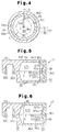
- a third embodiment of the present invention will be described with reference to Fig. 6 mainly in terms of the differences from the embodiment shown in Figs. 1 to 4.
- a cylindrical rim 350 corresponding to the cylindrical wall 34 in Fig. 2 is formed integrally with the head piece 31, as shown in Fig. 6.
- the body piece 32 has a peripheral rim 38, which is fitted in the open end of the annular rim 350.
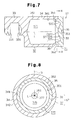
- the inner end face 37 of the head end wall 30 has a first tapered face 375, which joins the inner wall surface 351 of the annular rim 35, a second tapered surface 376, which is joined to the first tapered surface 375 and a flat central surface 377, which is joined to the second tapered surface 376.
- the tapered surfaces 375 and 376 have linear profiles. The closer a point on the first tapered surface 375 is to the axis L, the closer that point is to the outer end face 36. The closer a point on the second tapered surface 376 is to the axis L, the further that point is from the outer end face 36.
- the head piece 31 has a plate-like head end wall 40, as shown in Figs. 9(a) and 9(b).
- the head end wall 40 has an inner end face 41 that is planar and parallel to the outer end face 36.
- the inner end face 41 has a plurality of integral reinforcing ribs 39 (six ribs in this embodiment).
- the reinforcing ribs 39 extend radially from the axis L and are arranged at 60° angular intervals.
- Inner end portions 391 of the reinforcing ribs 39 are located at the axis L, and outer end portions 392 of the reinforcing ribs 39 are connected to the inner wall surface 351 of the annular rim 35.
- the inner end portions 391 are axially aligned with the positioning recess 361.
- the rear face 393 of each reinforcing rib 39 is parallel to the outer end face 36 of the head end wall 40. In other words, the thickness of each reinforcing rib 39 (as measured in the direction of the axis L) is the same over its entire length.
- This embodiment has the following advantages.
- the reinforcing ribs 39 formed on the inner end face 41 increase the surface area on the rear side of the head end wall 30. This reduces stress concentration in the head end wall 40 and limits the weight of the head end wall 40 compared with the case where the thickness of the head end wall is increased uniformly. Thus, the head end wall 40 is strong and is lighter than a simple plate-like head end wall.
- the reinforcing ribs 39 reduces the concentration of stress in their longitudinal directions.
- the reinforcing ribs 39 extend radially from the axis L of the head end wall 40. This reduces the concentration of stress in the head end wall 40.
- connection of all the reinforcing ribs 39 to the inner wall surface 351 of the annular rim 35 reduces the concentration of stress between the annular rim 35 and the head end wall 40.
- the inner end portions 391 of all the reinforcing ribs 39 are located at the axis L. This improves the strength of the head end wall 40 around the axis L. Further, the inner end portions 391 are aligned axially with the positioning recess 361. This compensates for the loss of strength in the head end wall 40 attributed to the positioning recess 361.
- the reinforcing ribs 39 are arranged around the axis L at equiangular intervals. This reduces the concentration of circumferential stress in the head end wall 40.
- the head piece 31 is formed by die casting, cutting or press molding.
- the two-piece structure facilitates formation of the reinforcing ribs 39 on the inner end face 41 of the head end wall 40.
- a sixth embodiment of the present invention will be described with reference to Figs. 10(a) and 10(b) mainly in terms of the differences from the embodiment shown in Figs. 9(a) and 9(b).
- a plurality of reinforcing ribs 42 are formed on the inner end face 41 of the head end wall 40.
- Each reinforcing rib 42 extends not from the axis L but from a point offset from the axis L and is connected to the inner wall surface 351 of the annular rim 35.
- the reinforcing ribs 42 are arranged around the axis L at equiangular intervals.
- the inner end portions 421 of the reinforcing ribs 42 define a rectangular box surrounding the axis L.
- the piston of the sixth embodiment has the same advantages as that of the embodiment shown in Figs. 9(a) and 9(b).
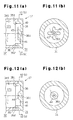
- a seventh embodiment of the present invention will be described with reference to Figs. 11(a) and 11(b) mainly in terms of the differences from the embodiment shown in Figs. 9(a) and 9(b).
- the piston of this embodiment is like that of the embodiment of Figs. 9(a) and 9(b), except that only four reinforcing ribs 43 are formed on the inner end face 41 of the head end wall 40 and that the ribs 43 are not connected to the inner wall surface 351 of the annular rim 35.
- a protrusion 44 is formed on the inner end face 41 of the head end wall 40.
- the protrusion 44 is centered on the axis L.
- the protrusion 44 corresponds only to the inner end portions 391 of the reinforcing ribs 39 in Fig. 9(a).
- the protrusion 44 has a substantially cylindrical shape.
- the protrusion 44 is smoothly joined to the inner end face 41.
- a protrusion 45 is formed on the inner end face 41 of the head end wall 40.
- the protrusion 45 has a ring-like form and is centered on the axis L.
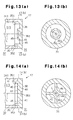
- FIG. 14(a) and 14(b) A tenth embodiment of the present invention will be described with reference to Figs. 14(a) and 14(b) mainly in terms of the differences from the embodiment shown in Figs. 12(a) and 12(b).
- the protrusion 44 and four reinforcing ribs 46 are formed on the inner end face 41 of the head end wall 40.
- the protrusion 44 is substantially the same as that shown in Fig. 12(a).
- the reinforcing ribs 46 extend radially from the protrusion 44 and are connected to the inner wall surface 351 of the annular rim 35.
- the reinforcing ribs 46 are arranged around the axis L at equiangular intervals.
- the protrusion 44 may be omitted to leave only the reinforcing ribs 46.
- FIG. 15(a) and 15(b) An eleventh embodiment of the present invention will be described with reference to Figs. 15(a) and 15(b) mainly in terms of the differences from the embodiment shown in Figs. 12(a) and 12(b).
- This embodiment is substantially the same as the embodiment shown in Figs. 12(a) and 12(b), except that a plurality of reinforcing ribs 47 are included.
- the reinforcing ribs 47 each have a triangular plate-like form and are located in the corner formed between the inner end face 41 of the head end wall 40 and the inner wall surface 351 of the annular rim 35.
- the reinforcing ribs 47 extend radially and are arranged around the axis L at equiangular intervals.
- the protrusion 44 may be omitted to leave only the reinforcing ribs 47.
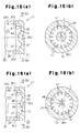
- FIG. 16(a) and 16(b) A twelfth embodiment of the present invention will be described with reference to Figs. 16(a) and 16(b) mainly in terms of the differences from the embodiment shown in Figs. 15(a) and 15(b).
- This embodiment is different from that shown in Figs. 15(a) and 15(b) in that the protrusion 44 is replaced with a plurality of reinforcing ribs 48.
- the reinforcing ribs 48 each have a triangular plate-like form and extend radially from the axis L at equiangular intervals.
- the radially outer reinforcing ribs 47 may be omitted to leave only the radially inner reinforcing ribs 48.
- a thirteenth embodiment of the present invention will be described with reference to Figs. 17(a) and 17(b) mainly in terms of the differences from the embodiment shown in Figs. 9(a) and 9(b).
- This embodiment is different from that shown in Figs. 9(a) and 9(b) in that the top face of each reinforcing rib 49 is curved, and that the number of the reinforcing ribs 49 is different from that of the embodiment shown in Figs. 9(a) and 9(b).
- the rear face 491 of each reinforcing rib 49 includes a concave surface 492 and a convex surface 493.
- the contour of the rear face 491, from the end of the inner wall surface 351 toward the axis L, first approaches the outer end face 36 and then departs from it.
- a fourteenth embodiment of the present invention will be described with reference to Figs. 18(a) and 18(b) mainly in terms of the differences from the embodiment shown in Figs. 1 to 4.
- This embodiment is different from that shown in Figs. 1 to 4 in that the protrusion 50 has a flat end face.
- the protrusion 50 extends from an annular concave surface 371, which smoothly joins the inner wall surface 351 of the annular rim 35.
- An annular convex surface 378 is smoothly joined to the concave portion 371, and a flat face 379 smoothly joins the annular convex surface 378.
- the annular convex surface 378 is a part of a sphere. The closer a point on the annular convex surface 378 is to the axis L, the further that point is from the outer end face 36.
- the flat face 379 is parallel to the outer end face 36.
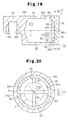
- a fifteenth embodiment of the present invention will be described with reference to Figs. 19 and 20 mainly in terms of the differences from the embodiment shown in Figs. 1 to 4.
- This embodiment is substantially the same as that shown in Figs. 1 to 4, except that a plurality of reinforcing ribs 60 are included.
- the reinforcing ribs 60 (four ribs in this embodiment) extend radially from the axis L and are connected to the inner wall surface 351 of the annular rim 35.
- the rear surface 601 of each reinforcing rib 60 is parallel to the outer end face 36.
- the reinforcing ribs 60 further improve the strength of the head end wall 30 compared with the embodiment shown in Figs. 1 to 4.
- FIG. 21 and 22 A sixteenth embodiment of the present invention will be described with reference to Figs. 21 and 22 mainly in terms of the differences from the embodiment shown in Figs. 19 and 20.
- This embodiment is substantially the same as the embodiment shown in Figs. 19 and 20, except that reinforcing ribs 70 each have a curved rear surface 701.
- the rear surface 701 is curved to match the contour of the inner end face 37 of the head end wall 30.
- the quantity of material necessary for forming the reinforcing ribs 70 is reduced compared with the embodiment shown in Figs. 19 and 20.
- Fig. 23(a) shows a first mold 51 and a second mold 52, which are used for casting the head piece 31.
- the first mold 51 has a portion that does not conform to the shape of the inner end face 37 of the head end wall 30. More specifically, the first mold 51 is designed and formed such that it forms an extra protrusion 54 on the inner end face 37. The protrusion 54 is not present in the finished product.
- a pushing rod 53 is fitted to the first mold 51 to move axially.
- the molds 51 and 52 are mated with each other, and in this state molten metal, based on aluminum, is poured into a casting space between the molds 51 and 52.
- the pushing rod 53 is urged in the axial direction Q shown in Fig. 23(a).
- the molten metal present in the portion corresponding to the extra protrusion 54 is pushed by the distal end of the pushing rod 53. This prevents formation of shrinkage cavities in a workpiece 310, which results after solidification of the molten metal.
- the workpiece 310 is taken out from the molds 51 and 52.
- a recess 541 matching the shape of the distal end of the pushing rod 53 remains in the extra protrusion 54.
- the extra protrusion 54 is removed by cutting with a cutting tool 55 such as an end mill.
- the portion of the inner end face 37 from which the extra protrusion 54 is removed forms the flat face 379 (see Fig. 18(a)).
- shrinkage cavities in the head piece 31 can be prevented. This improves the strength of the head piece 31.
- the extra protrusion 54 may not be cut off completely. In this case, the remaining extra protrusion 54 serves as an annular reinforcing rib.
- the curvature of the inner end face 37 of the head end wall 30 is not limited to the illustration but can be modified suitably.
- the inner end face 37 of the head end wall 30 may be formed by a combination of curved surfaces and tapered surfaces.
- a tapered surface may be located between the annular concave portion 371 and the inner wall surface 351 of the annular rim 35, or a tapered surface may be located between the annular groove-like surface 371 and the convex surface 372.
- the convex portion 372 may not be a part of a spherical face but may be of any type as long as it has a smooth curved surface.
- the flat central surface 377 may be replaced with a conical tapered surface 376 having an apex centered on the axis L.
- a recess may be formed on the flat central surface 377 shown in Fig. 7 or on the flat face 379 shown in Fig. 18(a).
- the first piston member may be connected to the second piston member using an adhesive.
- the first piston member may be connected to the second piston member by means of friction pressure.
- the first piston member may be connected to the second piston member by means of press fitting.
- a positioning recess 361 is formed on the outer end face of the head end wall.
- the present invention can be applied in those pistons that have no positioning recesses 361. Light and strong hollow pistons can be obtained again in such cases.
- a hollow piston has an end wall that receives pressure in a cylinder bore of a compressor.
- a reinforcing protrusion is formed on the inner end face of the end wall. The contour of the protrusion, from the radially outside portion toward the radially inside portion, first approaches the outer end face and then departs from the outer end face. Therefore, the piston is light and strong.
Landscapes
- Engineering & Computer Science (AREA)
- Mechanical Engineering (AREA)
- General Engineering & Computer Science (AREA)
- Manufacturing & Machinery (AREA)
- Compressor (AREA)
- Pistons, Piston Rings, And Cylinders (AREA)
- Compressors, Vaccum Pumps And Other Relevant Systems (AREA)
Applications Claiming Priority (4)
| Application Number | Priority Date | Filing Date | Title |
|---|---|---|---|
| JP2000101026 | 2000-04-03 | ||
| JP2000101020A JP3963064B2 (ja) | 2000-04-03 | 2000-04-03 | 圧縮機におけるピストン |
| JP2000101026A JP2001289162A (ja) | 2000-04-03 | 2000-04-03 | 圧縮機におけるピストン及びピストン製造方法 |
| JP2000101020 | 2000-04-03 |
Publications (2)
| Publication Number | Publication Date |
|---|---|
| EP1143143A2 true EP1143143A2 (fr) | 2001-10-10 |
| EP1143143A3 EP1143143A3 (fr) | 2002-11-13 |
Family
ID=26589352
Family Applications (1)
| Application Number | Title | Priority Date | Filing Date |
|---|---|---|---|
| EP01108328A Withdrawn EP1143143A3 (fr) | 2000-04-03 | 2001-04-02 | Piston de compresseur et son procédé de fabrication |
Country Status (5)
| Country | Link |
|---|---|
| US (1) | US20010047720A1 (fr) |
| EP (1) | EP1143143A3 (fr) |
| KR (1) | KR100472277B1 (fr) |
| CN (1) | CN1316595A (fr) |
| BR (1) | BR0101291A (fr) |
Cited By (1)
| Publication number | Priority date | Publication date | Assignee | Title |
|---|---|---|---|---|
| EP2990645A4 (fr) * | 2013-04-26 | 2016-12-21 | Kawasaki Heavy Ind Ltd | Piston situé dans un rotateur hydraulique, et rotateur hydraulique |
Families Citing this family (2)
| Publication number | Priority date | Publication date | Assignee | Title |
|---|---|---|---|---|
| CN101598121B (zh) * | 2009-07-09 | 2011-04-13 | 南京奥特佳冷机有限公司 | 斜盘式双头活塞式压缩机 |
| AU2014270792B2 (en) * | 2013-05-22 | 2017-08-31 | Hydac Drive Center Gmbh | Axial piston pump having a swash-plate type construction |
Citations (3)
| Publication number | Priority date | Publication date | Assignee | Title |
|---|---|---|---|---|
| JPH10281065A (ja) | 1997-04-02 | 1998-10-20 | Calsonic Corp | 斜板式コンプレッサの片頭型のピストン |
| JPH11107912A (ja) | 1997-10-08 | 1999-04-20 | Sanden Corp | 斜板式圧縮機 |
| JPH11294320A (ja) | 1998-04-15 | 1999-10-26 | Sanden Corp | 往復動式圧縮機 |
Family Cites Families (9)
| Publication number | Priority date | Publication date | Assignee | Title |
|---|---|---|---|---|
| US1489180A (en) * | 1921-06-11 | 1924-04-01 | George A Weidely | Piston construction |
| US1772187A (en) * | 1929-03-23 | 1930-08-05 | Gen Motors Corp | Piston pin |
| JPS56102365A (en) * | 1980-01-21 | 1981-08-15 | Honda Motor Co Ltd | Method of filling molten metal in vertical type die casting machine |
| US4350083A (en) * | 1980-09-29 | 1982-09-21 | Tecumseh Products Company | Heat barrier for refrigeration compressor piston |
| US4829954A (en) * | 1985-08-19 | 1989-05-16 | Morgado Ralph G | Method of forming self-sealing piston |
| CH675455A5 (en) * | 1988-02-17 | 1990-09-28 | Burckhardt Ag Maschf | Reciprocating compressor with drive side-open piston - has oil surge preventing partition inside piston guide section |
| DE4114985A1 (de) * | 1991-05-08 | 1992-11-12 | Buehler Ag | Verfahren zum nachverdichten und druck- oder spritzgiessmaschine hierfuer |
| JPH1077965A (ja) * | 1996-09-03 | 1998-03-24 | Zexel Corp | 可変容量型斜板式圧縮機 |
| US5878652A (en) * | 1997-12-05 | 1999-03-09 | Dresser-Rand Company | Cast, substantially hollow, piston body |
-
2001
- 2001-04-02 BR BR0101291-6A patent/BR0101291A/pt not_active IP Right Cessation
- 2001-04-02 KR KR10-2001-0017421A patent/KR100472277B1/ko not_active Expired - Fee Related
- 2001-04-02 CN CN01119209A patent/CN1316595A/zh active Pending
- 2001-04-02 EP EP01108328A patent/EP1143143A3/fr not_active Withdrawn
- 2001-04-02 US US09/824,324 patent/US20010047720A1/en not_active Abandoned
Patent Citations (3)
| Publication number | Priority date | Publication date | Assignee | Title |
|---|---|---|---|---|
| JPH10281065A (ja) | 1997-04-02 | 1998-10-20 | Calsonic Corp | 斜板式コンプレッサの片頭型のピストン |
| JPH11107912A (ja) | 1997-10-08 | 1999-04-20 | Sanden Corp | 斜板式圧縮機 |
| JPH11294320A (ja) | 1998-04-15 | 1999-10-26 | Sanden Corp | 往復動式圧縮機 |
Cited By (2)
| Publication number | Priority date | Publication date | Assignee | Title |
|---|---|---|---|---|
| EP2990645A4 (fr) * | 2013-04-26 | 2016-12-21 | Kawasaki Heavy Ind Ltd | Piston situé dans un rotateur hydraulique, et rotateur hydraulique |
| US10167855B2 (en) | 2013-04-26 | 2019-01-01 | Kawasaki Jukogyo Kabushiki Kaisha | Piston included in liquid-pressure rotating device and liquid-pressure rotating device |
Also Published As
| Publication number | Publication date |
|---|---|
| EP1143143A3 (fr) | 2002-11-13 |
| CN1316595A (zh) | 2001-10-10 |
| US20010047720A1 (en) | 2001-12-06 |
| BR0101291A (pt) | 2001-11-06 |
| KR100472277B1 (ko) | 2005-03-07 |
| KR20010095238A (ko) | 2001-11-03 |
Similar Documents
| Publication | Publication Date | Title |
|---|---|---|
| JP3777942B2 (ja) | 圧縮機用中空ピストンの製造方法 | |
| EP0896854B1 (fr) | Procédé de fabrication de piston pour compresseur à plateau en biais | |
| JPH09250451A (ja) | 容量可変型揺動斜板式圧縮機のピストン | |
| EP0857530B1 (fr) | Méthode pour l'usinage d'un piston de compresseur | |
| US6478558B2 (en) | Oscillating piston type compressor and method of manufacturing piston thereof | |
| EP1143143A2 (fr) | Piston de compresseur et son procédé de fabrication | |
| US6237467B1 (en) | Hydrostatic machine piston | |
| US6557454B2 (en) | Compressor pistons | |
| EP1143144B2 (fr) | Piston de compresseur et son procédé de fabrication | |
| JP3937690B2 (ja) | 圧縮機 | |
| US20020092151A1 (en) | Cast spherical crown shoe of compressor | |
| US7137197B2 (en) | Method of manufacturing a piston having a hollow piston head | |
| US20030084783A1 (en) | Piston for compressor and method of manufacturing the same | |
| JP2001107853A (ja) | 斜板式圧縮機用ピストンの製造方法 | |
| JPH09203378A (ja) | 斜板式コンプレッサ | |
| US5644949A (en) | Compressor cam and method for manufacturing the same | |
| EP1081377A2 (fr) | Structure de renforcement d'un piston creux d'un compresseur à plateau en biais | |
| JP3963064B2 (ja) | 圧縮機におけるピストン | |
| KR100222357B1 (ko) | 경사판 압축기용 피스톤의 제작 방법 | |
| KR100388826B1 (ko) | 압축기용 중공 피스톤 및 그 제조방법 | |
| KR100558701B1 (ko) | 용량가변형 사판식 압축기용 피스톤 | |
| JP2002054565A (ja) | 可変容量型斜板式圧縮機用ピストンおよびその製造方法 | |
| US20030075041A1 (en) | Piston for fluid machine and the fluid machine having the same | |
| JPH0979137A (ja) | 斜板式コンプレッサ | |
| JP2003193967A (ja) | 斜板式圧縮機用ピストンの製造方法 |
Legal Events
| Date | Code | Title | Description |
|---|---|---|---|
| PUAI | Public reference made under article 153(3) epc to a published international application that has entered the european phase |
Free format text: ORIGINAL CODE: 0009012 |
|
| 17P | Request for examination filed |
Effective date: 20010405 |
|
| AK | Designated contracting states |
Kind code of ref document: A2 Designated state(s): AT BE CH CY DE DK ES FI FR GB GR IE IT LI LU MC NL PT SE TR |
|
| AX | Request for extension of the european patent |
Free format text: AL;LT;LV;MK;RO;SI |
|
| RAP1 | Party data changed (applicant data changed or rights of an application transferred) |
Owner name: KABUSHIKI KAISHA TOYOTA JIDOSHOKKI |
|
| PUAL | Search report despatched |
Free format text: ORIGINAL CODE: 0009013 |
|
| AK | Designated contracting states |
Kind code of ref document: A3 Designated state(s): AT BE CH CY DE DK ES FI FR GB GR IE IT LI LU MC NL PT SE TR |
|
| AX | Request for extension of the european patent |
Free format text: AL;LT;LV;MK;RO;SI |
|
| AKX | Designation fees paid |
Designated state(s): DE FR IT |
|
| 17Q | First examination report despatched |
Effective date: 20030624 |
|
| STAA | Information on the status of an ep patent application or granted ep patent |
Free format text: STATUS: THE APPLICATION IS DEEMED TO BE WITHDRAWN |
|
| 18D | Application deemed to be withdrawn |
Effective date: 20050304 |