EP1143181A2 - Metallrohr mit einer innenseitigen Kunststoffverkleidung sowie Verfahren zu seiner Herstellung - Google Patents
Metallrohr mit einer innenseitigen Kunststoffverkleidung sowie Verfahren zu seiner Herstellung Download PDFInfo
- Publication number
- EP1143181A2 EP1143181A2 EP01108376A EP01108376A EP1143181A2 EP 1143181 A2 EP1143181 A2 EP 1143181A2 EP 01108376 A EP01108376 A EP 01108376A EP 01108376 A EP01108376 A EP 01108376A EP 1143181 A2 EP1143181 A2 EP 1143181A2
- Authority
- EP
- European Patent Office
- Prior art keywords
- metal tube
- plastic
- metal
- tube
- metal pipe
- Prior art date
- Legal status (The legal status is an assumption and is not a legal conclusion. Google has not performed a legal analysis and makes no representation as to the accuracy of the status listed.)
- Granted
Links
- 239000002184 metal Substances 0.000 title claims abstract description 48
- 239000004033 plastic Substances 0.000 title claims abstract description 30
- 229920003023 plastic Polymers 0.000 title claims abstract description 30
- 238000004519 manufacturing process Methods 0.000 title abstract description 3
- 239000007788 liquid Substances 0.000 claims abstract description 6
- 238000005253 cladding Methods 0.000 claims description 8
- 238000000034 method Methods 0.000 claims description 6
- 239000004810 polytetrafluoroethylene Substances 0.000 claims description 6
- 229920001343 polytetrafluoroethylene Polymers 0.000 claims description 6
- 239000006223 plastic coating Substances 0.000 claims 1
- 229910000831 Steel Inorganic materials 0.000 description 2
- 239000011248 coating agent Substances 0.000 description 2
- 238000000576 coating method Methods 0.000 description 2
- 239000000463 material Substances 0.000 description 2
- 239000010959 steel Substances 0.000 description 2
- 241001631457 Cannula Species 0.000 description 1
- 239000002131 composite material Substances 0.000 description 1
- 239000000126 substance Substances 0.000 description 1
- 230000007704 transition Effects 0.000 description 1
Images
Classifications
-
- F—MECHANICAL ENGINEERING; LIGHTING; HEATING; WEAPONS; BLASTING
- F16—ENGINEERING ELEMENTS AND UNITS; GENERAL MEASURES FOR PRODUCING AND MAINTAINING EFFECTIVE FUNCTIONING OF MACHINES OR INSTALLATIONS; THERMAL INSULATION IN GENERAL
- F16L—PIPES; JOINTS OR FITTINGS FOR PIPES; SUPPORTS FOR PIPES, CABLES OR PROTECTIVE TUBING; MEANS FOR THERMAL INSULATION IN GENERAL
- F16L9/00—Rigid pipes
- F16L9/14—Compound tubes, i.e. made of materials not wholly covered by any one of the preceding groups
- F16L9/147—Compound tubes, i.e. made of materials not wholly covered by any one of the preceding groups comprising only layers of metal and plastics with or without reinforcement
-
- B—PERFORMING OPERATIONS; TRANSPORTING
- B01—PHYSICAL OR CHEMICAL PROCESSES OR APPARATUS IN GENERAL
- B01L—CHEMICAL OR PHYSICAL LABORATORY APPARATUS FOR GENERAL USE
- B01L3/00—Containers or dishes for laboratory use, e.g. laboratory glassware; Droppers
- B01L3/02—Burettes; Pipettes
- B01L3/0289—Apparatus for withdrawing or distributing predetermined quantities of fluid
- B01L3/0293—Apparatus for withdrawing or distributing predetermined quantities of fluid for liquids
-
- B—PERFORMING OPERATIONS; TRANSPORTING
- B01—PHYSICAL OR CHEMICAL PROCESSES OR APPARATUS IN GENERAL
- B01L—CHEMICAL OR PHYSICAL LABORATORY APPARATUS FOR GENERAL USE
- B01L2300/00—Additional constructional details
- B01L2300/08—Geometry, shape and general structure
- B01L2300/0832—Geometry, shape and general structure cylindrical, tube shaped
-
- B—PERFORMING OPERATIONS; TRANSPORTING
- B01—PHYSICAL OR CHEMICAL PROCESSES OR APPARATUS IN GENERAL
- B01L—CHEMICAL OR PHYSICAL LABORATORY APPARATUS FOR GENERAL USE
- B01L2300/00—Additional constructional details
- B01L2300/16—Surface properties and coatings
Definitions
- the invention relates to a metal tube with an inside, the adherence of liquids reducing, firm plastic cladding arranged in the metal tube, especially cannula with a PTFE lining.
- the invention relates to a method for producing a such a metal pipe.
- Metal pipes often have to be covered with plastic on the inside be provided. That is for example the case with cannulas for samplers.
- the coating serves to adhere the remains of a taken Prevent sample so that it does not lead to procrastination can come between different samples.
- you create the necessary plastic cladding through liquid plastic that one lets it flow through the metal tube and it is for one Coating of the inner surface ensures.
- Metal pipes of the The above type must be connected to other facilities are, for example with a measuring device, in which flows through the cannulated sample. This requires a hose that is connected to the Cannula must be connected. Inevitably arises dead volume due to connections, which causes material carryover can be. It is therefore endeavored keep the number of connections as small as possible.
- the invention is based on the problem of a metal tube of the type mentioned in such a way that it is inside as inexpensively as possible with a plastic cladding can be provided and as free of dead volume as possible to be connected to another facility.
- Such a metal tube can over the lead out of it Plastic hose directly with, for example a measuring device, so that only a connection between the measuring device and the hose must be available as an interface. Thereby the number of interfaces is as small as possible, so that there is a risk of carry-over through dead spaces is correspondingly low.
- the invention allows everyone Advantages of a plastic hose can be used without that on the stability and geometry of a metal cannula must be dispensed with. By choosing the optimal one Plastic for the plastic hose, in particular PTFE, one achieves a high inner surface quality and high chemical resistance.
- the plastic tube is in very easily held the metal tube without the need for a composite if, according to an advantageous further development the invention of the plastic hose one reaching to the front end of the metal tube Reduced diameter of the metal pipe in this friction is held.
- the second problem namely the creation of a Process for producing a metal tube with a inside, reducing the adherence of liquids, plastic cladding fixed in the metal tube, especially a cannula with a PTFE liner, is solved according to the invention in that in the metal pipe inserted a plastic tube and that Then metal pipe in the front area by cold forming is reduced in diameter so that the Plastic hose there frictionally in the metal tube is held.
- Such a method can be carried out very inexpensively and leads to metal pipes with an optimal inner surface, which with the plastic hose just a single hose transition to one facility, for example a measuring system can be connected.
- the tip of the metal tube closes with the one inserted in it Hose flush if after cold forming machined the front end of the metal tube to a flush finish of the metal pipe and of the plastic hose.
- the invention permits various embodiments. One of them is shown in the drawing and will described below.
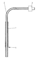
- the drawing shows a metal tube 1 in section Steel, which is a cannula for a sampler can act.
- this metal tube 1 leads from above forth as a plastic tubing 2 made of PTFE into it, which has a plug connection 3 at its upper end has, for example, with a not shown Measuring device can be connected.
- the metal pipe 1 has one created by hammering in the lower area Diameter reduction 4 through which the plastic hose 2 frictionally held in the metal tube 1 is.
Landscapes
- Chemical & Material Sciences (AREA)
- Engineering & Computer Science (AREA)
- General Engineering & Computer Science (AREA)
- Analytical Chemistry (AREA)
- Health & Medical Sciences (AREA)
- Clinical Laboratory Science (AREA)
- Chemical Kinetics & Catalysis (AREA)
- Mechanical Engineering (AREA)
- Sampling And Sample Adjustment (AREA)
- Laminated Bodies (AREA)
- Lining Or Joining Of Plastics Or The Like (AREA)
Abstract
Description
- 1
- Metallrohr
- 2
- Kunststoffschlauch
- 3
- Steckanschluss
- 4
- Durchmesserreduzierung
Claims (6)
- Metallrohr mit einer innenseitigen, das Anhaften von Flüssigkeiten reduzierenden, fest in dem Metallrohr angeordneten Kunststoffverkleidung, insbesondere Kanüle mit einer PTFE-Verkleidung, dadurch gekennzeichnet, dass die Verkleidung durch einen reibschlüssig in dem Metallrohr (1) gehaltenen, am vorderen Ende des Metallrohres (1) mit diesem bündig abschließenden und am anderen Ende aus ihm herausführenden Kunststoffschlauch (2) gebildet ist.
- Metallrohr nach Anspruch 1, dadurch gekennzeichnet, dass der Kunststoffschlauch (2) durch eine bis zum vorderen Ende des Metallrohres (1) reichende Durchmesserreduzierung (4) des Metallrohres (1) in diesem reibschlüssig gehalten ist.
- Metallrohr nach Anspruch 2, dadurch gekennzeichnet, dass die Durchmesserreduzierung (4) sich in etwa über 1/4 der Länge des Metallrohres (1) erstreckt.
- Verfahren zum Herstellung eines Metallrohres mit einer innenseitigen, das Anhaften von Flüssigkeiten reduzierenden, fest in dem Metallrohr angeordneten Kunststoffverkleidung, insbesondere einer Kanüle mit einer PTFE-Verkleidung, dadurch gekennzeichnet, dass in das Metallrohr ein Kunststoffschlauch eingeführt und das Metallrohr anschließend im vorderen Bereich durch Kaltverformen im Durchmesser reduziert wird, so dass der Kunststoffschlauch dort reibschlüssig in dem Metallrohr gehalten ist.
- Verfahren nach Anspruch 4, dadurch gekennzeichnet, dass das Kaltverformen durch Hämmern erfolgt.
- Verfahren nach den Ansprüchen 4 oder 5, dadurch gekennzeichnet, dass nach dem Kaltverformen das vordere Ende des Metallrohres spanabhebend bearbeitet wird, um einen bündigen Abschluss des Metallrohres und des Kunststoffschlauches herbeizuführen.
Applications Claiming Priority (2)
| Application Number | Priority Date | Filing Date | Title |
|---|---|---|---|
| DE10017606 | 2000-04-08 | ||
| DE10017606A DE10017606A1 (de) | 2000-04-08 | 2000-04-08 | Metallrohr mit einer innenseitigen Kunststoffverkleidung sowie Verfahren zu seiner Herstellung |
Publications (3)
| Publication Number | Publication Date |
|---|---|
| EP1143181A2 true EP1143181A2 (de) | 2001-10-10 |
| EP1143181A3 EP1143181A3 (de) | 2003-10-01 |
| EP1143181B1 EP1143181B1 (de) | 2006-11-08 |
Family
ID=7638111
Family Applications (1)
| Application Number | Title | Priority Date | Filing Date |
|---|---|---|---|
| EP01108376A Expired - Lifetime EP1143181B1 (de) | 2000-04-08 | 2001-04-03 | Verfahren zur Herstellung eines Metallrohrs mit einer innenseitigen Kunststoffverkleidung |
Country Status (3)
| Country | Link |
|---|---|
| EP (1) | EP1143181B1 (de) |
| AT (1) | ATE344902T1 (de) |
| DE (2) | DE10017606A1 (de) |
Cited By (2)
| Publication number | Priority date | Publication date | Assignee | Title |
|---|---|---|---|---|
| WO2007146837A2 (en) | 2006-06-14 | 2007-12-21 | Dionex Corporation | Sampling needle and methods of forming and using same |
| CN102565442A (zh) * | 2011-11-14 | 2012-07-11 | 上海神开石油化工装备股份有限公司 | 一种粘度计的吸样嘴装置 |
Families Citing this family (1)
| Publication number | Priority date | Publication date | Assignee | Title |
|---|---|---|---|---|
| DE102015119649B4 (de) | 2015-11-13 | 2020-12-17 | Dionex Softron Gmbh | Verfahren zur Herstellung eines Hohlraumelements mit thermoplastischer Beschichtung |
Family Cites Families (11)
| Publication number | Priority date | Publication date | Assignee | Title |
|---|---|---|---|---|
| DE7140981U (de) * | Felten & Guilleaume Gmbh | Metallrohr für den Transport von Flüssigkeiten und Gasen | ||
| GB449617A (en) * | 1934-12-31 | 1936-06-30 | Gen Electric Co Ltd | Improvements in the manufacture of tubing by plastic deformation |
| AU3788472A (en) * | 1971-01-15 | 1973-07-19 | Jury & Spiers Proprietary Limited | Composite pipe |
| FR2292175A1 (fr) * | 1974-11-19 | 1976-06-18 | Plastic Omnium Cie | Tubes renforces en matiere synthetique, notamment en ptfe |
| US4447076A (en) * | 1979-10-17 | 1984-05-08 | Oreco Iii, Inc. | Conduit assembly |
| GB8300154D0 (en) * | 1983-01-05 | 1983-02-09 | Hill H R | Sheathed pipe |
| WO1992022379A1 (en) * | 1991-06-13 | 1992-12-23 | Applied Research Systems Ars Holding N.V. | Pipetting probe with reduced reagent carryover |
| US5212992A (en) * | 1991-06-14 | 1993-05-25 | Medical Laboratory Automation, Inc. | Capacitive probe sensor with reduced effective stray capacitance |
| US5468453A (en) * | 1993-06-14 | 1995-11-21 | Cirrus Diagnostics, Inc. | Low carryover pipette probe |
| AU3432597A (en) * | 1996-05-23 | 1997-12-09 | Moller Feinmechanik Gmbh & Co. Kg | Sampler for liquids |
| US5935523A (en) * | 1997-05-29 | 1999-08-10 | Medical Laboratory Automation, Inc. | Apparatus for accessing a sealed container |
-
2000
- 2000-04-08 DE DE10017606A patent/DE10017606A1/de not_active Withdrawn
-
2001
- 2001-04-03 AT AT01108376T patent/ATE344902T1/de not_active IP Right Cessation
- 2001-04-03 EP EP01108376A patent/EP1143181B1/de not_active Expired - Lifetime
- 2001-04-03 DE DE50111397T patent/DE50111397D1/de not_active Expired - Lifetime
Non-Patent Citations (1)
| Title |
|---|
| None |
Cited By (5)
| Publication number | Priority date | Publication date | Assignee | Title |
|---|---|---|---|---|
| WO2007146837A2 (en) | 2006-06-14 | 2007-12-21 | Dionex Corporation | Sampling needle and methods of forming and using same |
| EP2027446A4 (de) * | 2006-06-14 | 2011-03-09 | Dionex Corp | Probennadel und verfahren zum formen und verwenden derselben |
| US8313476B2 (en) | 2006-06-14 | 2012-11-20 | Dionex Corporation | Sampling needle and methods of forming and using same |
| CN102565442A (zh) * | 2011-11-14 | 2012-07-11 | 上海神开石油化工装备股份有限公司 | 一种粘度计的吸样嘴装置 |
| CN102565442B (zh) * | 2011-11-14 | 2013-04-10 | 上海神开石油化工装备股份有限公司 | 一种粘度计的吸样嘴装置 |
Also Published As
| Publication number | Publication date |
|---|---|
| DE50111397D1 (de) | 2006-12-21 |
| EP1143181A3 (de) | 2003-10-01 |
| EP1143181B1 (de) | 2006-11-08 |
| ATE344902T1 (de) | 2006-11-15 |
| DE10017606A1 (de) | 2001-10-11 |
Similar Documents
| Publication | Publication Date | Title |
|---|---|---|
| DE3903551C2 (de) | Verbindungsteil einer Leitungskupplung | |
| DE3602499A1 (de) | Kupplungsnippel | |
| DE20310390U1 (de) | Anschlussdichtung mit Ratschenzähnen | |
| DE1908888A1 (de) | Rohrverbindung und Verfahren zu ihrer Herstellung | |
| DE3140928A1 (de) | "verfahren und vorrichtung zum nachtraeglichen einziehen von fernmeldekabeln in versorgungsleitungen | |
| EP2545315B1 (de) | Vorrichtung zum verbinden einer ein fluid führenden leitung mit einem benachbarten bauteil | |
| DE19502764A1 (de) | Verfahren und Vorrichtung zum Prüfen von gasführenden Rohrleitungen | |
| EP0393802A2 (de) | Verfahren zur Vorbehandlung der Verbindungselemente einer gasdichten Rohrverbindung | |
| EP1143181A2 (de) | Metallrohr mit einer innenseitigen Kunststoffverkleidung sowie Verfahren zu seiner Herstellung | |
| DE2251397A1 (de) | Vorrichtung zur genauen fluidteilung | |
| DE69322955T2 (de) | Beschichtungsrohr | |
| DE3503494C2 (de) | Ölfeldrohr | |
| CH369322A (de) | Bowdenzug | |
| DE102008004152A1 (de) | Rohrleitung mit einem Anschlussstück | |
| EP1457775B1 (de) | Schlauch aus hochtemperaturbeständigem Kunststoff, Verfahren zur Gestaltung des Endes eines solchen Schlauches | |
| DE69607841T2 (de) | Verfahren und vorrichtung zum verlegen von rohren | |
| EP0825149A1 (de) | Verfahren und Vorrichtung zur Abgabe von unterschiedlichen Kraftstoffsorten an einer Zapfstelle | |
| EP0694143B1 (de) | Rohrleitungsverbindung, rohrleitungsverbinder und hydraulikvorrichtung zur herstellung von rohrleitungsverbindungen | |
| EP1278001A2 (de) | Pressverbindung zwischen einem Fitting und einem Rohrende | |
| DE202012103586U1 (de) | Vorrichtung zur Entnahme von Fluid aus einer Rohrleitung | |
| DE2342528A1 (de) | Vorrichtung zum verbinden eines wellrohrendes mit dem ende eines glattrohres | |
| DE4243625C2 (de) | Anschlußstutzen | |
| DE102019133972B3 (de) | Schlauch-konnektor-verbindung | |
| DE19633932C2 (de) | Verfahren zum Sanieren von wenigstens teilweise unter der Oberfläche verlegten Rohrleitungen | |
| DE3124613A1 (de) | Verfahren zum auskleiden einer rohrleitung mit einer flexiblen, zylinderfoermigen folie |
Legal Events
| Date | Code | Title | Description |
|---|---|---|---|
| PUAI | Public reference made under article 153(3) epc to a published international application that has entered the european phase |
Free format text: ORIGINAL CODE: 0009012 |
|
| AK | Designated contracting states |
Kind code of ref document: A2 Designated state(s): AT BE CH CY DE DK ES FI FR GB GR IE IT LI LU MC NL PT SE TR |
|
| AX | Request for extension of the european patent |
Free format text: AL;LT;LV;MK;RO;SI |
|
| PUAL | Search report despatched |
Free format text: ORIGINAL CODE: 0009013 |
|
| AK | Designated contracting states |
Kind code of ref document: A3 Designated state(s): AT BE CH CY DE DK ES FI FR GB GR IE IT LI LU MC NL PT SE TR |
|
| AX | Request for extension of the european patent |
Extension state: AL LT LV MK RO SI |
|
| RIC1 | Information provided on ipc code assigned before grant |
Ipc: 7F 16L 9/147 A Ipc: 7G 01N 35/10 B Ipc: 7B 01L 11/00 B Ipc: 7B 01L 3/02 B |
|
| 17P | Request for examination filed |
Effective date: 20040327 |
|
| AKX | Designation fees paid |
Designated state(s): AT BE CH CY DE DK ES FI FR GB GR IE IT LI LU MC NL PT SE TR |
|
| 17Q | First examination report despatched |
Effective date: 20050103 |
|
| GRAP | Despatch of communication of intention to grant a patent |
Free format text: ORIGINAL CODE: EPIDOSNIGR1 |
|
| RTI1 | Title (correction) |
Free format text: METHOD FOR PRODUCING A METAL PIPE WITH INTERNAL PLASTICS COVERING |
|
| GRAS | Grant fee paid |
Free format text: ORIGINAL CODE: EPIDOSNIGR3 |
|
| GRAA | (expected) grant |
Free format text: ORIGINAL CODE: 0009210 |
|
| AK | Designated contracting states |
Kind code of ref document: B1 Designated state(s): AT BE CH CY DE DK ES FI FR GB GR IE IT LI LU MC NL PT SE TR |
|
| PG25 | Lapsed in a contracting state [announced via postgrant information from national office to epo] |
Ref country code: IE Free format text: LAPSE BECAUSE OF FAILURE TO SUBMIT A TRANSLATION OF THE DESCRIPTION OR TO PAY THE FEE WITHIN THE PRESCRIBED TIME-LIMIT Effective date: 20061108 Ref country code: FI Free format text: LAPSE BECAUSE OF FAILURE TO SUBMIT A TRANSLATION OF THE DESCRIPTION OR TO PAY THE FEE WITHIN THE PRESCRIBED TIME-LIMIT Effective date: 20061108 Ref country code: NL Free format text: LAPSE BECAUSE OF FAILURE TO SUBMIT A TRANSLATION OF THE DESCRIPTION OR TO PAY THE FEE WITHIN THE PRESCRIBED TIME-LIMIT Effective date: 20061108 |
|
| REG | Reference to a national code |
Ref country code: GB Ref legal event code: FG4D Free format text: NOT ENGLISH |
|
| REG | Reference to a national code |
Ref country code: CH Ref legal event code: EP |
|
| REG | Reference to a national code |
Ref country code: IE Ref legal event code: FG4D Free format text: LANGUAGE OF EP DOCUMENT: GERMAN |
|
| REF | Corresponds to: |
Ref document number: 50111397 Country of ref document: DE Date of ref document: 20061221 Kind code of ref document: P |
|
| PG25 | Lapsed in a contracting state [announced via postgrant information from national office to epo] |
Ref country code: DK Free format text: LAPSE BECAUSE OF FAILURE TO SUBMIT A TRANSLATION OF THE DESCRIPTION OR TO PAY THE FEE WITHIN THE PRESCRIBED TIME-LIMIT Effective date: 20070208 Ref country code: SE Free format text: LAPSE BECAUSE OF FAILURE TO SUBMIT A TRANSLATION OF THE DESCRIPTION OR TO PAY THE FEE WITHIN THE PRESCRIBED TIME-LIMIT Effective date: 20070208 |
|
| GBT | Gb: translation of ep patent filed (gb section 77(6)(a)/1977) |
Effective date: 20070124 |
|
| PG25 | Lapsed in a contracting state [announced via postgrant information from national office to epo] |
Ref country code: ES Free format text: LAPSE BECAUSE OF FAILURE TO SUBMIT A TRANSLATION OF THE DESCRIPTION OR TO PAY THE FEE WITHIN THE PRESCRIBED TIME-LIMIT Effective date: 20070219 |
|
| RAP2 | Party data changed (patent owner data changed or rights of a patent transferred) |
Owner name: MOELLER MEDICAL GMBH & CO.KG |
|
| REG | Reference to a national code |
Ref country code: CH Ref legal event code: PFA Owner name: MOELLER MEDICAL GMBH & CO.KG Free format text: MOELLER FEINMECHANIK GMBH & CO. KG#WASSERKUPPENSTRASSE 29 - 31#36043 FULDA (DE) -TRANSFER TO- MOELLER MEDICAL GMBH & CO.KG#WASSERKUPPENSTRASSE 29-31#36043 FULDA (DE) Ref country code: CH Ref legal event code: NV Representative=s name: PPS POLYVALENT PATENT SERVICE AG |
|
| ET | Fr: translation filed | ||
| PG25 | Lapsed in a contracting state [announced via postgrant information from national office to epo] |
Ref country code: PT Free format text: LAPSE BECAUSE OF FAILURE TO SUBMIT A TRANSLATION OF THE DESCRIPTION OR TO PAY THE FEE WITHIN THE PRESCRIBED TIME-LIMIT Effective date: 20070409 |
|
| NLT2 | Nl: modifications (of names), taken from the european patent patent bulletin |
Owner name: MOELLER MEDICAL GMBH & CO.KG Effective date: 20070228 |
|
| NLV1 | Nl: lapsed or annulled due to failure to fulfill the requirements of art. 29p and 29m of the patents act | ||
| REG | Reference to a national code |
Ref country code: IE Ref legal event code: FD4D |
|
| REG | Reference to a national code |
Ref country code: FR Ref legal event code: CD |
|
| PLBE | No opposition filed within time limit |
Free format text: ORIGINAL CODE: 0009261 |
|
| STAA | Information on the status of an ep patent application or granted ep patent |
Free format text: STATUS: NO OPPOSITION FILED WITHIN TIME LIMIT |
|
| 26N | No opposition filed |
Effective date: 20070809 |
|
| BERE | Be: lapsed |
Owner name: MOLLER FEINMECHANIK G.M.B.H. & CO. KG Effective date: 20070430 |
|
| PG25 | Lapsed in a contracting state [announced via postgrant information from national office to epo] |
Ref country code: BE Free format text: LAPSE BECAUSE OF NON-PAYMENT OF DUE FEES Effective date: 20070430 |
|
| PG25 | Lapsed in a contracting state [announced via postgrant information from national office to epo] |
Ref country code: GR Free format text: LAPSE BECAUSE OF FAILURE TO SUBMIT A TRANSLATION OF THE DESCRIPTION OR TO PAY THE FEE WITHIN THE PRESCRIBED TIME-LIMIT Effective date: 20070209 |
|
| PG25 | Lapsed in a contracting state [announced via postgrant information from national office to epo] |
Ref country code: AT Free format text: LAPSE BECAUSE OF NON-PAYMENT OF DUE FEES Effective date: 20070403 |
|
| PG25 | Lapsed in a contracting state [announced via postgrant information from national office to epo] |
Ref country code: MC Free format text: LAPSE BECAUSE OF NON-PAYMENT OF DUE FEES Effective date: 20070430 |
|
| REG | Reference to a national code |
Ref country code: CH Ref legal event code: PFA Owner name: MOELLER MEDICAL GMBH Free format text: MOELLER MEDICAL GMBH & CO.KG#WASSERKUPPENSTRASSE 29-31#36043 FULDA (DE) -TRANSFER TO- MOELLER MEDICAL GMBH#WASSERKUPPENSTRASSE 29-31#36043 FULDA (DE) |
|
| PG25 | Lapsed in a contracting state [announced via postgrant information from national office to epo] |
Ref country code: CY Free format text: LAPSE BECAUSE OF FAILURE TO SUBMIT A TRANSLATION OF THE DESCRIPTION OR TO PAY THE FEE WITHIN THE PRESCRIBED TIME-LIMIT Effective date: 20061108 Ref country code: LU Free format text: LAPSE BECAUSE OF NON-PAYMENT OF DUE FEES Effective date: 20070403 |
|
| PG25 | Lapsed in a contracting state [announced via postgrant information from national office to epo] |
Ref country code: TR Free format text: LAPSE BECAUSE OF FAILURE TO SUBMIT A TRANSLATION OF THE DESCRIPTION OR TO PAY THE FEE WITHIN THE PRESCRIBED TIME-LIMIT Effective date: 20061108 |
|
| REG | Reference to a national code |
Ref country code: FR Ref legal event code: CD |
|
| REG | Reference to a national code |
Ref country code: CH Ref legal event code: PFA Owner name: MOELLER MEDICAL GMBH Free format text: MOELLER MEDICAL GMBH#WASSERKUPPENSTRASSE 29-31#36043 FULDA (DE) -TRANSFER TO- MOELLER MEDICAL GMBH#WASSERKUPPENSTRASSE 29-31#36043 FULDA (DE) |
|
| REG | Reference to a national code |
Ref country code: FR Ref legal event code: PLFP Year of fee payment: 16 |
|
| REG | Reference to a national code |
Ref country code: FR Ref legal event code: PLFP Year of fee payment: 17 |
|
| REG | Reference to a national code |
Ref country code: FR Ref legal event code: PLFP Year of fee payment: 18 |
|
| PGFP | Annual fee paid to national office [announced via postgrant information from national office to epo] |
Ref country code: FR Payment date: 20200420 Year of fee payment: 20 Ref country code: CH Payment date: 20200420 Year of fee payment: 20 Ref country code: DE Payment date: 20200420 Year of fee payment: 20 |
|
| PGFP | Annual fee paid to national office [announced via postgrant information from national office to epo] |
Ref country code: IT Payment date: 20200423 Year of fee payment: 20 Ref country code: GB Payment date: 20200427 Year of fee payment: 20 |
|
| REG | Reference to a national code |
Ref country code: DE Ref legal event code: R071 Ref document number: 50111397 Country of ref document: DE |
|
| REG | Reference to a national code |
Ref country code: CH Ref legal event code: PL |
|
| REG | Reference to a national code |
Ref country code: GB Ref legal event code: PE20 Expiry date: 20210402 |
|
| PG25 | Lapsed in a contracting state [announced via postgrant information from national office to epo] |
Ref country code: GB Free format text: LAPSE BECAUSE OF EXPIRATION OF PROTECTION Effective date: 20210402 |