EP1143477B1 - Sicherheitseinrichtung für elektrisches Gerät vom Schutzschalter Typ - Google Patents
Sicherheitseinrichtung für elektrisches Gerät vom Schutzschalter Typ Download PDFInfo
- Publication number
- EP1143477B1 EP1143477B1 EP00440097A EP00440097A EP1143477B1 EP 1143477 B1 EP1143477 B1 EP 1143477B1 EP 00440097 A EP00440097 A EP 00440097A EP 00440097 A EP00440097 A EP 00440097A EP 1143477 B1 EP1143477 B1 EP 1143477B1
- Authority
- EP
- European Patent Office
- Prior art keywords
- shoe
- safety device
- lever
- sectionalisation
- electrical apparatus
- Prior art date
- Legal status (The legal status is an assumption and is not a legal conclusion. Google has not performed a legal analysis and makes no representation as to the accuracy of the status listed.)
- Expired - Lifetime
Links
- 230000002093 peripheral effect Effects 0.000 claims description 8
- 230000009471 action Effects 0.000 claims description 5
- 238000006073 displacement reaction Methods 0.000 claims description 5
- 230000007935 neutral effect Effects 0.000 claims description 4
- 238000013519 translation Methods 0.000 claims description 4
- 230000007246 mechanism Effects 0.000 claims description 3
- 230000000007 visual effect Effects 0.000 claims description 2
- 210000005069 ears Anatomy 0.000 abstract description 3
- 229910000679 solder Inorganic materials 0.000 abstract description 2
- 230000002265 prevention Effects 0.000 abstract 1
- 230000000903 blocking effect Effects 0.000 description 7
- 230000035882 stress Effects 0.000 description 6
- 238000003466 welding Methods 0.000 description 6
- 210000000003 hoof Anatomy 0.000 description 5
- 230000006870 function Effects 0.000 description 3
- 230000008901 benefit Effects 0.000 description 2
- 238000013461 design Methods 0.000 description 2
- 238000009434 installation Methods 0.000 description 2
- 230000037452 priming Effects 0.000 description 2
- 230000000284 resting effect Effects 0.000 description 2
- 238000005476 soldering Methods 0.000 description 2
- 240000008042 Zea mays Species 0.000 description 1
- 230000004913 activation Effects 0.000 description 1
- 230000004075 alteration Effects 0.000 description 1
- 238000013459 approach Methods 0.000 description 1
- 238000000429 assembly Methods 0.000 description 1
- 210000003323 beak Anatomy 0.000 description 1
- 230000005540 biological transmission Effects 0.000 description 1
- 230000000295 complement effect Effects 0.000 description 1
- 238000005520 cutting process Methods 0.000 description 1
- 230000007547 defect Effects 0.000 description 1
- 238000012938 design process Methods 0.000 description 1
- 238000005516 engineering process Methods 0.000 description 1
- 230000002349 favourable effect Effects 0.000 description 1
- 238000005457 optimization Methods 0.000 description 1
- 238000003825 pressing Methods 0.000 description 1
- 230000000750 progressive effect Effects 0.000 description 1
- 230000009131 signaling function Effects 0.000 description 1
- 238000004513 sizing Methods 0.000 description 1
- 230000001360 synchronised effect Effects 0.000 description 1
- 230000008646 thermal stress Effects 0.000 description 1
- 230000009466 transformation Effects 0.000 description 1
- 238000012800 visualization Methods 0.000 description 1
Images





Classifications
-
- H—ELECTRICITY
- H01—ELECTRIC ELEMENTS
- H01H—ELECTRIC SWITCHES; RELAYS; SELECTORS; EMERGENCY PROTECTIVE DEVICES
- H01H71/00—Details of the protective switches or relays covered by groups H01H73/00 - H01H83/00
- H01H71/10—Operating or release mechanisms
- H01H71/50—Manual reset mechanisms which may be also used for manual release
- H01H71/501—Means for breaking welded contacts; Indicating contact welding or other malfunction of the circuit breaker
Definitions
- the present invention relates to a safety device for electrical devices including modular, more specifically for devices capable of cutting, and is intended to prevent the lockout of an apparatus when the contacts have been accidentally welded, due in particular to a magnetothermal defect .
- the lockout is performed by means of a padlocking kit to lock the device in one of its normal operating positions, open or closed contacts.
- This kit applies to the joystick, which is therefore blocked in one of its stable positions corresponding to the aforementioned states. It is attached to the housing of the electrical device via at least one hole in an ear disposed along the opening in which the handle moves.
- the activation of the lockout kit fixing it to the housing of the device by inserting a member in at least one of said orifices, then allows the installation of a padlock that prohibits removal of said kit.
- the operator then knows in principle the state of the contacts, and can work without a deliberate manual alteration of this state is to be feared.
- the threshold force corresponds to a rupture of the internal components of the device, otherwise the offset of the stop would be inoperative and inefficient to solve the problem.
- the drum carrying the handle further comprises a recess which is arranged to coincide with orifices provided in the side walls of the circuit breaker housing, in order to authorize the lockout, and whose respective positions are offset when the contacts are welded. .
- control handle is blocked at the lockout holes when the contacts are welded to each other.
- the invention therefore relates to electrical devices including modular circuit breaker type having at least one movable contact for cooperating with at least one fixed contact, said movable contact being secured to a pivoting contact carrier connected to a control lever pivoting between two stable positions, a first position corresponding to the opening of said contacts and a second position corresponding to the closure of the contacts, said handle moving in an opening in the front of the circuit breaker box, along lateral ears provided with at least one orifice allowing a lockout blocking the handle in the open or closed position of the contacts.
- the safety device comprises rotary control means whose pivoting is controlled simultaneously with the rotation of the movable contact, which can actuate during the closing operation of the contacts a movable member in the housing to bring it closer to said handle, means being provided on the latter and on said member to cooperate when the lever is actuated in the direction of the opening of the contacts and when these remain closed by welding, in order to lock the lever in an intermediate position between said two stable positions, in which it obstructs the said orifices orifices in the side lugs, return means reminding the movable member in a rest position further away from the lever for moving the latter in the position corresponding to the opening of the contacts when there is no welding.
- said movable member cooperates with the housing or a part fixed to the housing so that when the handle is locked in the intermediate position, the forces exerted on said handle are reflected in said housing.
- said control means consist of at least one control arm pivoting at the same time and about the same axis as the movable contact, which can actuate a shoe disposed near the handle and pivoted in the housing around a axis parallel to the previous one.
- the shoe connected to the housing of the device, allows to separate the control of the joystick, and the effort that accompanies the internal mechanism ensuring the operation of the circuit breaker, only when sticking contacts. In other words, as soon as a weld of these occurs, the shoe comes into play and drifts the force applied to the handle towards the housing.
- the force exerted on the handle initially produces a small angular stroke of the lock during which at least a portion of it is deformed .
- the shoe intervenes, and the forces are then transmitted to the circuit breaker housing, said lock then no longer under stress.
- Each control arm is preferably directly integral with a movable contact, but it is also possible to make it integral with the contact carrier.
- the important criterion is that it rotates at the same time as the moving contact, and thus reflects its displacement.
- each of these is equipped at its free end with a finger oriented to exert a pressure transmitting to the shoe at least a portion of the rotational movement of the movable contact.
- the shoe of the invention comprises at one of its ends a pivot shaft to which is fixed a spring, said shoe being further provided with at least one extension intended to cooperate with a control arm.
- the ends of the pivot shaft are free to rotate in bearings fitted to the circuit breaker housing.
- Each extension of the shoe actually makes contact, at the end of the closing operation, with the finger equipping the end of the control arm.
- the rotation printed by the movable contacts or the contact carrier is transmitted to the shoe via these extensions, located on the peripheral path of the fingers, and allows rotation in the opposite direction of the shoe.
- the spring exerts a return action tending to pivot the shoe in the opposite direction of the direction conferred by the control arm or arms, by pressing on an element fixed to the casing of the circuit breaker.
- the goal is to return the hoof to its initial resting position when operating the joystick to open the contacts.
- the shoe is disposed between the handle and the magnetic subassembly, the spring then resting on the yoke of said magnetic subassembly.
- the spring has a wavy shape, the corrugations developing over a length calculated so that its stiffness allows a return to its rest position in a manner synchronized with the movement of the handle in case of opening of the contacts.
- This form is advantageous because the restoring force it produces depends on the length of the spring, and can therefore easily be adjusted.
- the shoe, its pivot shaft and the return spring are made in one piece of plastic material.
- Means for terminating the locking of the lever in an intermediate position have been mentioned previously: according to one possibility, these means consist of the shoe in at least one surface whose orientation at rest is close to the plane containing the pivot axes the lever on the one hand, and the orifices made in the side lugs on the other hand, and then approaches when the shoe is actuated by the or the control arm.
- the periphery of the drum of the handle comprises an outgrowth located substantially opposite the operating lever of said handle, comprising in particular a surface oriented so that a relative sliding is possible with the aforementioned surface of the shoe when they meet, the hoof then blocking the joystick.
- control arm In case of bonding of the contacts, the control arm (s) keep the shoe in the position in which it is brought to close said contacts, close to the lever and more particularly, because of its location, close to the rotary drum supporting the control lever. It then interferes with the trajectory of the outgrowth provided on said drum, and the two surfaces can come into contact. They are oriented in such a way that the action of the protuberance on the free rotating shoe produces a relative sliding, resulting in continuing the rotation of the sabot initiated by the control arm or arms, to result in a complete blockage which does not more intervene these, as opposed to the two surfaces.
- the lock is not subject to any constraint, which is not the case of the spring, that the additional rotation results in forcing a little more, or the housing in which pivots the hoof , essential receiver of said constraints via the bearings in which the shoe shaft rotates.
- the attachment surfaces each comprise, at their free edges intended to come into contact with each other, a rounded boss, the boss of the shoe being at the time of the first contact between the boss of the protuberance of the drum and the periphery of it. This characteristic ensures the priming of the connection between the surfaces of the shoe and the protrusion, before the aforementioned relative sliding.
- the stiffness of the spring allows the shoe to return to its rest position quickly, so that there is no interference with the trajectory of the protrusion when the handle is manipulated in the sense of opening contacts.
- each movable contact comprises a control arm extending radially relative to the axis of rotation of said contact and forming an angle approximately right with the latter, only the extension of the neutral side shoe being provided with a contact surface with the surface of a protrusion positioned on the same side on the drum of the joystick.
- the rotary control means whose pivoting is controlled simultaneously with the rotation of the movable contact consist of a member pivoting about an axis parallel to the axis of pivoting of the contact holder, connected to the latter which rotates, and in turn displaces a shoe disposed near the handle and guided in the housing in the direction of the handle during the closing operation of the contacts.
- the shoe is moved by the rotation of a rotary member rotating about an axis separate from that of the contact carrier, and therefore the movable contact.
- the pivoting member comprises a first radial-shaped arm provided with a pin inserted into a radial notch of the contact holder. Similarly, it may comprise a second radial arm at the end of which is disposed the shoe.
- the second arm comprising the shoe is preferably placed radially substantially at least once. opposite of the first radial arm.
- a lock of the handle must be made in a suitable position preventing lockout, that is to say the right of the orifices fitted to the side lugs surrounding the controller.
- the end of the shoe adjacent the handle has a geometry provided to achieve a locking of the joystick by contact with the surface peripheral thereof when it is actuated in the direction of the opening of the contacts without said shoe moves because of the sticking of the contacts.
- the end of the shoe comprises, in its lower surface, a notch cooperating with a ratchet protruding from the outer peripheral surface of the handle.
- the ratchet can for example protrude from the outer surface of a protrusion of the drum of the handle provided to house the end of a connecting rod participating in the mechanism lock.
- said ratchet is disposed at a distance from the drum of the handle, and that we benefit for the purposes of the invention from a favorable configuration allowing the use of an existing protrusion.
- the shoe is distinct from the pivoting member.
- the second radial arm is provided with a pin inserted into a notch, of parallel shape to said arm, in which it is free in translation.
- This provision with a degree of freedom allows in particular to transmit a force to the hoof without necessarily imposing a path of displacement, which can be fixed by an external guide to these elements.
- the shoe is guided in rectilinear translation in the housing, in a parallel direction to the front of said housing, so that its path meets that of the peripheral configuration of the joystick.
- the shoe can incidentally be used in another signaling function: said shoe preferably moves close to a portion of the casing of the casing provided with a light allowing the visualization of said shoe, which comprises visual elements reflecting the position of the contacts.
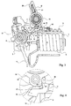
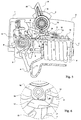
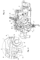
- Each movable contact (4) is equipped with a control arm (8), developing radially substantially at right angles to said contact (4), the center of the mark consisting of the axis of rotation (9) of the lock (S).
- Each arm (8) is provided at its free end with a finger (10) for transmitting the movement imparted by the lock (S) to the movable contact (4).
- a shoe (11) has at one of its ends an extension (12) intended to cooperate with the finger (10) of the control arm (8).
- the other end of this shoe (11) comprises a shaft (13) housed in bearings (15) of the casing (A), to which is fixed a corrugated spring (14), the free end of which is located, in a position of rest of the shoe (11) illustrated in this figure, near the magnetic yoke (7).
- the movement of the shoe (11) aims in fact to bring the surface (17), appearing at an upper shoulder of the shoe (11), from the periphery of the shoe. trajectory of a surface (18) providing an outgrowth (19) of the drum (16) so that their respective trajectories interfere in precise circumstances.
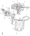
- FIG. 7 shows the invention seen from the phase side of a phase-neutral circuit breaker, and makes it possible to get a more precise idea of a possible configuration of the control arm (8), the pressure finger (10). ) and the shape of the shoe (11).
- This comprises two parts intended to cooperate with the two control arms (8) integral with the two movable contacts.
- the extension (12) appearing in the foreground, which is the one on the phase side, is moreover not provided with a shoulder or an attachment surface as defined above for the locking of the joystick ( M) in the intermediate position.
- the drum (16) of the latter does not have, on this side, protrusion.
- the hooking function is performed only on one side, the neutral side, hence an asymmetry of shapes.
- FIGS. 8 and 9 which also clearly show the one-piece constitution of the shoe (11) and the spring (14), separated by a shaft (13) whose two ends, projecting in particular laterally from the cylinder head (7), are intended to be housed in bearings created directly in the shells forming the housing (A), so as to derive the forces exerted on the handle (M), in the case of soldering the contacts (4, 5). on said housing (A).
- the locking of the handle (M) then takes place at a predetermined position, at the orifices (21) of the ears (O) bordering the window made in the front (1) of the circuit breaker for the movement of the handle (M). .
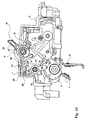
- the differential switch shown in FIG. 10 comprises a control lever (M) operable from the front (1) of the housing (A) and which moves between lateral lugs (O).
- a lock (S ') connects a contact carrier (3) to the handle (M), via rods (2, 42).
- the contact carrier (3) is itself connected to a member (30) pivoting about an axis (31).
- This member (30) comprises a first arm (32) of radial appearance of which an end pin is slidably disposed in a U-shaped housing (33) of the contact holder (3).
- Said member (30) comprises a second arm (34), also of radial shape, of which at least one end trunnion (35) is equivalently placed sliding in a U-shaped housing of a shoe (36). guided in rectilinear translation in the housing (A), along the front (1), in the direction of the handle (M).
- the shoe (36) is disposed on the left of the device, away from the handle (M), since the contacts (4, 5) are open.
- a protrusion (37) equips the periphery of the drum (16) of the handle (M), said protrusion (37) itself comprising a ratchet (38) provided to cooperate with a notch of the shoe (36) (see below ) via a surface (39).
- said shoe (36) is, on the contrary, moved to the right, in the direction of the lever (M) of the switch, in a position such that it could interfere with said elements (37, 38) disposed on the periphery of the drum (16) of the handle (M).
- This is the position corresponding to the closed contacts (4, 5) in which said peripheral elements (37, 38) are, however, angularly distant from the shoe (36).
- Figure 12 shows the position of the shoe (36) when said contacts (4, 5) are glued. They are then in the same position as in Figure 11, but the positioning of the joystick (M) has changed. This has been brought back to its position corresponding theoretically to the opening of the contacts, and the protrusion (37) accommodating an end of the link (2) then comes into contact with the shoe (36), as clearly appears in FIG. figure 13.
- the ratchet (38) located at the periphery of said protrusion (37) has a contact surface (39) (see FIG. 13) oriented so that at the moment of said contact, it is substantially parallel to a homologous surface (40) provided in the lower part of the shoe (36). According to one possibility, this surface (40) appears at a notch made at the lower corner of the shoe (36) proximal of the handle (M).
- this figure represents a window (41), made in the facade (1) facing the shoe (36), and which allows a tracking of the state of the contacts through information disposed on said shoe (36).
- a color code may for example be used on the upper surface of said shoe (36) to indicate that the contacts (4, 5) are in such or such a position.
Landscapes
- Breakers (AREA)
- Mechanical Control Devices (AREA)
- Driving Mechanisms And Operating Circuits Of Arc-Extinguishing High-Tension Switches (AREA)
- Emergency Protection Circuit Devices (AREA)
- Switch Cases, Indication, And Locking (AREA)
Claims (27)
- Sicherheitsvorrichtung zum Verhindern der Sperrung eines modularen, zum Trennen geeigneten, elektrischen Geräts, umfassend mindestens einen mobilen Kontakt (4) der dazu bestimmt ist, mit mindestens einem festen Kontakt (5) zusammenzuwirken, wobei der mobile Kontakt (4) mit einem Kontakthalter (3) verbunden ist, der schwenkbar mit einem Steuergriff (M) verbunden ist, der schwenkbar zwischen zwei stabilen Positionen ist, einer ersten Position, die der Öffnung der Kontakte (4; 5) entspricht und einer zweiten Position, die der Schließung der Kontakte (4; 5) entspricht, wobei der Griff (M) sich in einer Öffnung, die in der Vorderseite (1) des Gehäuses (A) des Schalters ausgeführt ist, entlang den Längsösen (O) verschiebt, die mit mindestens einem Loch (21) versehen sind, was ein Einklemmen ermöglicht, welche den Griff (M) in einer geöffneten Position der Kontakte (4; 5) festklemmt, dadurch gekennzeichnet, dass sie drehbare Steuermittel (8; 30) umfasst, deren Schwenkung simultan zur Rotation des mobilen Kontakts (4) gesteuert wird, die im Verlauf des Schließens der Kontakte (4; 5) eine mobile Einheit (11; 36) in dem Gehäuse (A) betätigen können, um es dem Griff (M) näherzubringen, wobei die Mittel auf letzteren und auf der Einheit (11; 36) vorgesehen sind, um zusammenzuwirken, wenn der Griff (M) in der Richtung der Öffnung der Kontakt (4; 5) betätigt wird betätigt wird und wenn dieser durch Verbinden geschlossen bleibt, in Hinblick darauf, dass der Griff (M) in einer Zwischen-Position zwischen den zwei stabilen Positionen festgeklemmt, in denen er das oder die Löcher (21), die in den Längsösen (O) ausgeführt sind, blockiert, wobei Rückstellmittel (14) die mobile Einheit (11) in eine Zustandsposition zurückzieht, die entfernter von dem Griff (M) ist und es ermöglicht, ihn in eine Position zu verschieben, die der Öffnung der Kontakte (4; 5) entspricht, wenn sie nicht verschweißt sind.
- Sicherheitsvorrichtung zum Verhindern der Sperrung eines modularen, zum Trennen geeigneten, elektrischen Geräts gemäß den vorhergehenden Anspruch, dadurch gekennzeichnet, dass die mobile Einheit (11; 36) mit dem Gehäuse (A) oder einem Teil, das an dem Gehäuse (A) befestigt ist, zusammenwirkt, sodass wenn der Griff (M) in einer Zwischenposition festklemmt, die Beanspruchung, die auf den Griff (M) ausgeübt wird, auf das Gehäuse (A) reflektiert wird.
- Sicherheitsvorrichtung zum Verhindern der Sperrung eines modularen, zum Trennen geeigneten, elektrischen Geräts gemäß einem der Ansprüche 1 oder 2, dadurch gekennzeichnet, dass die Steuermittel aus mindestens einem Steuerarm (8) bestehen, der zur gleichen Zeit und um die gleiche Achse (9) wie der mobile Kontakt (4) schwenkbar ist, der einen Schuh (11) bewegen kann, welcher in der Nähe des Griffs (M) angeordnet ist und in dem Gehäuse (A) um eine Achse (13), parallel zur Vorhergehenden, schwenkbar ist.
- Sicherheitsvorrichtung zum Verhindern der Sperrung eines modularen, zum Trennen geeigneten, elektrischen Geräts gemäß einem der vorhergehenden Ansprüche, dadurch gekennzeichnet, dass jeder Steuerarm (8) mit einem mobilen Kontakt (4) verbunden ist.
- Sicherheitsvorrichtung zum Verhindern der Sperrung eines modularen, zum Trennen geeigneten, elektrischen Geräts gemäß Anspruch 3, dadurch gekennzeichnet, dass jeder Steuerarm mit einem Kontakthalter (3) verbunden ist.
- Sicherheitsvorrichtung zum Verhindern der Sperrung eines modularen, zum Trennen geeigneten, elektrischen Geräts gemäß einem der Ansprüche 3 bis 5, dadurch gekennzeichnet, dass jeder Steuerarm (8) an seinem freien Endstück mit einem Finger (10) ausgestattet ist, der ausgerichtet ist, einen Druck auszuüben, der auf den Schuh (11) mindestens einen Teil der Rotationsbewegung des mobilen Kontakts (4) überträgt.
- Sicherheitsvorrichtung zum Verhindern der Sperrung eines modularen, zum Trennen geeigneten, elektrischen Geräts gemäß einem der Ansprüche 3 bis 6, dadurch gekennzeichnet, dass der Schuh (11) an dem einem seiner Endstücke eine schwenkbare Welle (13) umfasst, an dem eine Feder (14) befestigt ist, wobei der Schuh (11) unter anderem mit mindestens einer Verlängerung (12) versehen ist, die dafür vorgesehen ist, mit dem Steuerarm (8) zusammenzuwirken.
- Sicherheitsvorrichtung zum Verhindern der Sperrung eines modularen, zum Trennen geeigneten, elektrischen Geräts gemäß einem der vorhergehenden Ansprüche, dadurch gekennzeichnet, dass die Endstücke der schwenkbare Welle (13) des Schuhs (11) frei in der Rotation in den Lagern sind, die in dem Gehäuse (A) des Schalters vorgesehen sind.
- Sicherheitsvorrichtung zum Verhindern der Sperrung eines modularen, zum Trennen geeigneten, elektrischen Geräts gemäß einem der Ansprüche 7 und 8, dadurch gekennzeichnet, dass die Feder (14) eine Rückstellaktion ausführt, die dazu strebt, den Schuh (11) entgegen der durch den oder die Steuerarme (8) verliehen Richtung mithilfe eines an dem Gehäuse (A) des Schalters befestigten Elements, zu schwenken.
- Sicherheitsvorrichtung zum Verhindern der Sperrung eines modularen, zum Trennen geeigneten, elektrischen Geräts gemäß einem der vorhergehenden Ansprüche, dadurch gekennzeichnet, dass der Schuh (11) zwischen dem Griff (M) und der magnetischen Untereinheit (B) angeordnet ist, wobei die Feder (14) sich auf der Kammer (7) der magnetischen Untereinheit (B) abstützt.
- Sicherheitsvorrichtung zum Verhindern der Sperrung eines modularen, zum Trennen geeigneten, elektrischen Geräts gemäß einem der Ansprüche 7 bis 10, dadurch gekennzeichnet, dass die Feder (14) eine wellige Form zeigt, wobei die Welligkeit sich auf einer Länge entwickelt, die so berechnet ist, damit ihre Steifheit eine Rückkehr in ihre Erholungsposition auf eine synchronisierte Weise mit der Verschiebung des Griffs (M) im Falle der Öffnung der Kontakte (4; 5) ermöglicht.
- Sicherheitsvorrichtung zum Verhindern der Sperrung eines modularen, zum Trennen geeigneten, elektrischen Geräts gemäß einem der Ansprüche 7 bis 11, dadurch gekennzeichnet, dass der Schuh (11), seine schwenkbare Welle (13) und seine Rückstellfeder (14) aus einem einzigen Stück aus Kunststoffmaterial verwirklicht sind.
- Sicherheitsvorrichtung zum Verhindern der Sperrung eines modularen, zum Trennen geeigneten, elektrischen Geräts gemäß einem der Ansprüche 7 bis 12, dadurch gekennzeichnet, dass der Schuh (11) mindestens eine Oberfläche (17) umfasst, deren Ausrichtung einerseits benachbart zu der Ebene ist, die die Schwenkachsen des Griffs (M) enthält und andererseits zu dem oder den Löchern (21) mit denen die lateralen Ösen (O) versehen sind, und die sich nähert, wenn der Schuh (11) durch den oder die Steuerarme (8) betätig wird.
- Sicherheitsvorrichtung zum Verhindern der Sperrung eines modularen, zum Trennen geeigneten, elektrischen Geräts gemäß einem der vorhergehenden Ansprüche, dadurch gekennzeichnet, dass die Peripherie der Trommel (16) des Griffs (M) einen Vorsprung (19) umfasst, der im Wesentlichen auf der Gegenseite des Manövrierhebels (20) des Griffes (M) angeordnet ist, der insbesondere eine Oberfläche (18) umfasst, die so ausgerichtet ist, dass ein Gleiten relativ zur Oberfläche (17) des Schuhs (11) möglich ist, wenn sie sich treffen, der Schuh (11) klemmt dann den Griff (M) fest.
- Sicherheitsvorrichtung zum Verhindern der Sperrung eines modularen, zum Trennen geeigneten, elektrischen Geräts gemäß einem der vorhergehenden Ansprüche, dadurch gekennzeichnet, dass die Oberflächen (17; 18) auf Höhe ihrer freien Kanten, die vorgesehen sind in Kontakt miteinander zu treten, einen runden Buckel (22; 23) umfassen, wobei der Buckel (22) des Schuhs (11) sich beim ersten Kontakt zwischen dem Buckel (23) des Vorsprungs (19) der Trommel (16) und der Peripherie davon befindet.
- Multipolares Schutzgerät, das mit einer Sicherheitsvorrichtung gemäß der vorhergehenden Ansprüche versehen ist, dadurch gekennzeichnet, dass jeder mobile Kontakt (4) einen Steuerarm (8) umfasst, der sich radial in Bezug auf die Rotationsachse (9) der Kontakte (4) erstreckt und einen näherungsweise rechten Winkel mit Letzterem bildet, wobei alleine die Verlängerung des Schuhs (11), die sich an einer neutralen Seite befindet, mit einer Kontaktoberfläche (17) mit der Oberfläche (18) eines Vorsprungs (19) ausgestattet ist, die an der gleichen Seite auf der Trommel (16) des Steuergriffs (M) positioniert ist.
- Sicherheitsvorrichtung zum Verhindern der Sperrung eines modularen, zum Trennen geeigneten, elektrischen Geräts gemäß einem der Ansprüche 1 und 2, dadurch gekennzeichnet, dass die rotierenden Steuermittel aus einer Einheit (30) bestehen, die schwenkbar um eine Achse (31) parallel zur Schwenkachse (9) der Kontakthalter (3) ist, verbunden mit Letzterem, der ihn zur Rotation veranlasst und bei seiner Umdrehung einen Schuh (36) verschiebt, der in der Nähe des Griffs (M) angeordnet ist und durch das Gehäuse (A) in die Richtung des Griffs (M) geführt wird, bis zur Operation der Schließungen der Kontakte (4; 5).
- Sicherheitsvorrichtung zum Verhindern der Sperrung eines modularen, zum Trennen geeigneten, elektrischen Geräts gemäß einem der vorhergehenden Ansprüche, dadurch gekennzeichnet, dass die Schwenkeinheit (30) einen ersten Arm (32) mit radialem Verlauf umfasst, der mit in einer radialen Kerbe (33) des Kontakthalter (3) eingefügten Lagerzapfens versehen ist.
- Sicherheitsvorrichtung zum Verhindern der Sperrung eines modularen, zum Trennen geeigneten, elektrischen Geräts gemäß einem der Ansprüche 17 und 18, dadurch gekennzeichnet, dass die Schwenkeinheit (30) einen zweiten Arm (34) mit radialem Verlauf umfasst, an dessen Endstück der Schuh (36) angebracht ist.
- Sicherheitsvorrichtung zum Verhindern der Sperrung eines modularen, zum Trennen geeigneten, elektrischen Geräts gemäß einem der Ansprüche 18 und 19, dadurch gekennzeichnet, dass der zweite Arm (34), der den Schuh (36) umfasst, radial im Wesentlichen auf der Gegenseite des ersten radialen Arms (32) liegt.
- Sicherheitsvorrichtung zum Verhindern der Sperrung eines modularen, zum Trennen geeigneten, elektrischen Geräts gemäß einem der Ansprüche 17 bis 20, dadurch gekennzeichnet, dass das Endstück des Schuhs (36) benachbart zum Griff (M) eine Geometrie zeigt, die vorgesehen ist, ein Festklemmen des Griffs (M) durch Kontakt mit der peripheren Oberfläche davon zu verwirklichen, wenn sie in Richtung einer Öffnung der Kontakte (4; 5) betätigt wird, ohne dass sich der Schuh (36) verschiebt, wie es mit einer Verklebung der Kontakte (4; 5) der Fall wäre.
- Sicherheitsvorrichtung zum Verhindern der Sperrung eines modularen, zum Trennen geeigneten, elektrischen Geräts gemäß der vorhergehenden Ansprüche, dadurch gekennzeichnet, dass das Endstück des Schuhs (36), an seiner inneren Oberfläche, eine Kerbe umfasst, die mit einer Ratsche (38) zusammenwirkt, die aus der externen peripheren Oberfläche (37) des Griffs (M) herausragt.
- Sicherheitsvorrichtung zum Verhindern der Sperrung eines modularen, zum Trennen geeigneten, elektrischen Geräts gemäß einem der Ansprüche, dadurch gekennzeichnet, dass die Ratsche (38) aus der externen Oberfläche eines Vorsprungs es (37) der Trommel (16) des Griffs (M) herausragt, der vorgesehen ist, das Endstück eines Schaltgestänges (2) unterzubringen, der an einem Sicherheitsmechanismus (S') mitwirkt.
- Sicherheitsvorrichtung zum Verhindern der Sperrung eines modularen, zum Trennen geeigneten, elektrischen Geräts gemäß einem der Ansprüche 17 bis 23, dadurch gekennzeichnet, dass der Schuh (36) verschieden von der Schwenkeinheit (30) ist.
- Sicherheitsvorrichtung zum Verhindern der Sperrung eines modularen, zum Trennen geeigneten, elektrischen Geräts gemäß der vorhergehenden Ansprüche, dadurch gekennzeichnet, dass der zweite Arm mit radialem Verlauf mit einem Lagerzapfen (35) versehen ist, der in eine Kerbe, mit parallelem Verlauf zum Arm (34), eingefügt ist, in dem er frei in der Translation ist.
- Sicherheitsvorrichtung zum Verhindern der Sperrung eines modularen, zum Trennen geeigneten, elektrischen Geräts gemäß den vorhergehenden Ansprüche, dadurch gekennzeichnet, dass der Schuh (36) in der Translation geradlinig in dem Gehäuse (A), in einer Richtung mit parallelem Verlauf zu einer Außenseite (1) des Gehäuses (A) geführt wird, sodass seine Bahn die der peripheren Konfiguration des Griffs (M) trifft.
- Sicherheitsvorrichtung zum Verhindern der Sperrung eines modularen, zum Trennen geeigneten, elektrischen Geräts gemäß einem der Ansprüche 25 bis 26, dadurch gekennzeichnet, dass der Schuh (36) sich in der Nähe eines Teils der Außenseite (1) des Gehäuses (A) verschiebt, der mit einer Lampe (41) versehen ist, die eine Visualisierung des Schuhs (36) ermöglicht, der visuelle Elemente umfasst, die die Position der Kontakte (4; 5) wiedergeben.
Priority Applications (3)
| Application Number | Priority Date | Filing Date | Title |
|---|---|---|---|
| AT00440097T ATE355604T1 (de) | 2000-04-07 | 2000-04-07 | Sicherheitseinrichtung für elektrisches gerät vom schutzschalter typ |
| DE60033632T DE60033632T2 (de) | 2000-04-07 | 2000-04-07 | Sicherheitseinrichtung für elektrisches Gerät vom Schutzschalter Typ |
| EP00440097A EP1143477B1 (de) | 2000-04-07 | 2000-04-07 | Sicherheitseinrichtung für elektrisches Gerät vom Schutzschalter Typ |
Applications Claiming Priority (1)
| Application Number | Priority Date | Filing Date | Title |
|---|---|---|---|
| EP00440097A EP1143477B1 (de) | 2000-04-07 | 2000-04-07 | Sicherheitseinrichtung für elektrisches Gerät vom Schutzschalter Typ |
Publications (2)
| Publication Number | Publication Date |
|---|---|
| EP1143477A1 EP1143477A1 (de) | 2001-10-10 |
| EP1143477B1 true EP1143477B1 (de) | 2007-02-28 |
Family
ID=8174113
Family Applications (1)
| Application Number | Title | Priority Date | Filing Date |
|---|---|---|---|
| EP00440097A Expired - Lifetime EP1143477B1 (de) | 2000-04-07 | 2000-04-07 | Sicherheitseinrichtung für elektrisches Gerät vom Schutzschalter Typ |
Country Status (3)
| Country | Link |
|---|---|
| EP (1) | EP1143477B1 (de) |
| AT (1) | ATE355604T1 (de) |
| DE (1) | DE60033632T2 (de) |
Cited By (1)
| Publication number | Priority date | Publication date | Assignee | Title |
|---|---|---|---|---|
| WO2017156978A1 (zh) * | 2016-03-14 | 2017-09-21 | 乐清市沃斯托电气有限公司 | 断路器 |
Families Citing this family (2)
| Publication number | Priority date | Publication date | Assignee | Title |
|---|---|---|---|---|
| DE102009007475A1 (de) | 2009-01-30 | 2010-08-05 | Siemens Aktiengesellschaft | Schaltmechanismus für ein Schaltgerät mit einem bei einem verschweißten Kontaktglied und bei einer Öffnungsbetätigung in einer Zwischenschaltstellung verbleibenden Schalthebel |
| CN103367058A (zh) * | 2013-07-31 | 2013-10-23 | 成都电业局双流供电局 | 自动空气开关 |
Family Cites Families (9)
| Publication number | Priority date | Publication date | Assignee | Title |
|---|---|---|---|---|
| FR2390569A1 (fr) * | 1977-05-09 | 1978-12-08 | Hazemeyer Sa | Dispositif pour le cadenassage d'un appareil electrique |
| FR2660794B1 (fr) * | 1990-04-09 | 1996-07-26 | Merlin Gerin | Mecanisme de commande d'un disjoncteur electrique. |
| US5219070A (en) * | 1991-07-12 | 1993-06-15 | Westinghouse Electric Corp. | Lockable rotary handle operator for circuit breaker |
| DE4322215C2 (de) * | 1993-07-03 | 1995-08-24 | Kloeckner Moeller Gmbh | Abschließbarer Drehantrieb für Leistungsschalter |
| DE4439374C1 (de) * | 1994-11-04 | 1996-02-15 | Kloeckner Moeller Gmbh | Abschließbare Handbetätigungsvorrichtung zum Ein- und Ausschalten von gekapselten elektrischen Schaltgeräten, insbesondere von Leistungsschaltern |
| ATE159123T1 (de) * | 1994-11-04 | 1997-10-15 | Kloeckner Moeller Gmbh | Abschliessbare handbetätigungsvorrichtung für gekapselte elektrische schaltgeräte |
| FR2733087B1 (fr) * | 1995-04-13 | 1997-06-06 | Schneider Electric Sa | Appareil electrique et notamment disjoncteur equipe d'un dispositif de securite |
| EP0827173B1 (de) * | 1996-03-15 | 2006-10-18 | Mitsubishi Denki Kabushiki Kaisha | Lastschalter |
| US5927484A (en) * | 1997-05-28 | 1999-07-27 | Eaton Corporation | Circuit breaker with welded contact interlock, gas sealing cam rider and double rate spring |
-
2000
- 2000-04-07 EP EP00440097A patent/EP1143477B1/de not_active Expired - Lifetime
- 2000-04-07 AT AT00440097T patent/ATE355604T1/de not_active IP Right Cessation
- 2000-04-07 DE DE60033632T patent/DE60033632T2/de not_active Expired - Lifetime
Cited By (3)
| Publication number | Priority date | Publication date | Assignee | Title |
|---|---|---|---|---|
| WO2017156978A1 (zh) * | 2016-03-14 | 2017-09-21 | 乐清市沃斯托电气有限公司 | 断路器 |
| GB2552628A (en) * | 2016-03-14 | 2018-01-31 | Yueqing Onesto Electric Co Ltd | Breaker |
| GB2552628B (en) * | 2016-03-14 | 2022-03-30 | Yueqing Onesto Electric Co Ltd | Breaker |
Also Published As
| Publication number | Publication date |
|---|---|
| DE60033632D1 (de) | 2007-04-12 |
| ATE355604T1 (de) | 2006-03-15 |
| DE60033632T2 (de) | 2007-10-31 |
| EP1143477A1 (de) | 2001-10-10 |
Similar Documents
| Publication | Publication Date | Title |
|---|---|---|
| EP2460172B1 (de) | Drehbares steuersystem für einen stromschutzschalter | |
| EP1659601B1 (de) | Mechanische Steuervorrichtung für ein elektrisches Gerät mit drei Schaltstellungen mit einem Wahlhebel der mit eine Nocke wirkt | |
| EP1170769B1 (de) | Schnelleinschaltvorrichtung für Modulschutzschalter | |
| EP2131378B1 (de) | Steuervorrichtung für ein elektrisches Schaltgerät, das mit einer Signalisierungsvorrichtung für die Verschweißung der Kontakte ausgestattet ist, und mit dieser Vorrichtung ausgestattetes elektrisches Schaltgerät | |
| EP2368256B1 (de) | Mechanische auslöseeinrichtung für eine leitungs-schaltanlage | |
| EP1975971A1 (de) | Bedienungsvorrichtung eines elektrischen Sicherungsgeräts und elektrisches Sicherungsgerät, das sie umfasst | |
| EP0338930A1 (de) | Lastschalter oder Differential-Lastschalter | |
| EP0696041B1 (de) | Schutzschalter | |
| WO2001069635A1 (fr) | Commande electrique de disjoncteur | |
| EP1143477A1 (de) | Sicherheitseinrichtung für elektrisches Gerät vom Schutzschalter Typ | |
| EP2717284B1 (de) | Bedienungsvorrichtung eines elektrischen Schutzschaltgeräts, und diese umfassendes elektrisches Schutzschaltgerät | |
| EP2377139B1 (de) | Vorrichtung zur fernbetätigung und damit versehener schutzschalter | |
| EP1703533B1 (de) | Anzeigesystem für magnetische Fehler | |
| EP0657909A1 (de) | Elektrischer Schalter mit Fehlerauslosung | |
| EP2518752B1 (de) | Anzeiger der Störungsauslösung durch die Position des Handsteuerhebels | |
| EP0311668A1 (de) | Schutzschaltgerät mit vereinfachtem auslösemechanismus | |
| FR2708377A1 (fr) | Entraînement tournant verrouillable pour sectionneurs de puissance. | |
| EP1111644B1 (de) | Sicherheitsvorrichtung für elektrisches Gerät | |
| EP2339606B1 (de) | Elektrischer Verriegelungsmechanismus zum Schutz einer Leitung mit Differentialfunktion | |
| EP3249673B1 (de) | Vorrichtung zur signalisierung einer elektrischen störung in einem elektrischen schutzgerät, und elektrisches schutzgerät, das eine solche vorrichtung umfasst | |
| EP2758977B1 (de) | Stromleitungsschutzvorrichtung mit anzeige eines elektrischen fehlers in der leitung | |
| EP2359379B1 (de) | Steuermechanismus für eine fernbediente abschneideeinrichtung, abschneideeinrichtung und fernbediente unterbrecherschaltung mit einem solchen mechanismus | |
| EP1241692B1 (de) | Abschliessvorrichtung mit Vorhängeschloss für ein modulares elektrisches Gerät | |
| EP1026350A1 (de) | Türgriff für Kraftfahrzeug | |
| EP3134910B1 (de) | Vorrichtung mit beweglichem kontakt ohne leitfähige litze |
Legal Events
| Date | Code | Title | Description |
|---|---|---|---|
| PUAI | Public reference made under article 153(3) epc to a published international application that has entered the european phase |
Free format text: ORIGINAL CODE: 0009012 |
|
| AK | Designated contracting states |
Kind code of ref document: A1 Designated state(s): AT BE CH CY DE DK ES FI FR GB GR IE IT LI LU MC NL PT SE |
|
| AX | Request for extension of the european patent |
Free format text: AL;LT;LV;MK;RO;SI |
|
| 17P | Request for examination filed |
Effective date: 20011112 |
|
| AKX | Designation fees paid |
Free format text: AT BE CH CY DE DK ES FI FR GB GR IE IT LI LU MC NL PT SE |
|
| GRAP | Despatch of communication of intention to grant a patent |
Free format text: ORIGINAL CODE: EPIDOSNIGR1 |
|
| RIN1 | Information on inventor provided before grant (corrected) |
Inventor name: ROIATTI, JEAN-MARIE Inventor name: SITZ, THIERRY Inventor name: DECKERT, FRANCIS Inventor name: DIEBOLD, FRANCIS Inventor name: FORSTER, DIDIER Inventor name: HASENFRATZ, DANIEL |
|
| GRAS | Grant fee paid |
Free format text: ORIGINAL CODE: EPIDOSNIGR3 |
|
| GRAA | (expected) grant |
Free format text: ORIGINAL CODE: 0009210 |
|
| AK | Designated contracting states |
Kind code of ref document: B1 Designated state(s): AT BE CH CY DE DK ES FI FR GB GR IE IT LI LU MC NL PT SE |
|
| PG25 | Lapsed in a contracting state [announced via postgrant information from national office to epo] |
Ref country code: IE Free format text: LAPSE BECAUSE OF FAILURE TO SUBMIT A TRANSLATION OF THE DESCRIPTION OR TO PAY THE FEE WITHIN THE PRESCRIBED TIME-LIMIT Effective date: 20070228 Ref country code: FI Free format text: LAPSE BECAUSE OF FAILURE TO SUBMIT A TRANSLATION OF THE DESCRIPTION OR TO PAY THE FEE WITHIN THE PRESCRIBED TIME-LIMIT Effective date: 20070228 Ref country code: AT Free format text: LAPSE BECAUSE OF FAILURE TO SUBMIT A TRANSLATION OF THE DESCRIPTION OR TO PAY THE FEE WITHIN THE PRESCRIBED TIME-LIMIT Effective date: 20070228 Ref country code: NL Free format text: LAPSE BECAUSE OF FAILURE TO SUBMIT A TRANSLATION OF THE DESCRIPTION OR TO PAY THE FEE WITHIN THE PRESCRIBED TIME-LIMIT Effective date: 20070228 Ref country code: DK Free format text: LAPSE BECAUSE OF FAILURE TO SUBMIT A TRANSLATION OF THE DESCRIPTION OR TO PAY THE FEE WITHIN THE PRESCRIBED TIME-LIMIT Effective date: 20070228 |
|
| REG | Reference to a national code |
Ref country code: GB Ref legal event code: FG4D Free format text: NOT ENGLISH |
|
| REG | Reference to a national code |
Ref country code: CH Ref legal event code: EP |
|
| REF | Corresponds to: |
Ref document number: 60033632 Country of ref document: DE Date of ref document: 20070412 Kind code of ref document: P |
|
| REG | Reference to a national code |
Ref country code: IE Ref legal event code: FG4D Free format text: LANGUAGE OF EP DOCUMENT: FRENCH |
|
| PG25 | Lapsed in a contracting state [announced via postgrant information from national office to epo] |
Ref country code: SE Free format text: LAPSE BECAUSE OF FAILURE TO SUBMIT A TRANSLATION OF THE DESCRIPTION OR TO PAY THE FEE WITHIN THE PRESCRIBED TIME-LIMIT Effective date: 20070531 |
|
| PG25 | Lapsed in a contracting state [announced via postgrant information from national office to epo] |
Ref country code: ES Free format text: LAPSE BECAUSE OF FAILURE TO SUBMIT A TRANSLATION OF THE DESCRIPTION OR TO PAY THE FEE WITHIN THE PRESCRIBED TIME-LIMIT Effective date: 20070608 |
|
| PG25 | Lapsed in a contracting state [announced via postgrant information from national office to epo] |
Ref country code: PT Free format text: LAPSE BECAUSE OF FAILURE TO SUBMIT A TRANSLATION OF THE DESCRIPTION OR TO PAY THE FEE WITHIN THE PRESCRIBED TIME-LIMIT Effective date: 20070730 |
|
| NLV1 | Nl: lapsed or annulled due to failure to fulfill the requirements of art. 29p and 29m of the patents act | ||
| GBV | Gb: ep patent (uk) treated as always having been void in accordance with gb section 77(7)/1977 [no translation filed] |
Effective date: 20070228 |
|
| REG | Reference to a national code |
Ref country code: IE Ref legal event code: FD4D |
|
| PG25 | Lapsed in a contracting state [announced via postgrant information from national office to epo] |
Ref country code: GB Free format text: LAPSE BECAUSE OF FAILURE TO SUBMIT A TRANSLATION OF THE DESCRIPTION OR TO PAY THE FEE WITHIN THE PRESCRIBED TIME-LIMIT Effective date: 20070228 |
|
| REG | Reference to a national code |
Ref country code: CH Ref legal event code: PL |
|
| BERE | Be: lapsed |
Owner name: HAGER ELECTRO S.A. Effective date: 20070430 |
|
| PLBE | No opposition filed within time limit |
Free format text: ORIGINAL CODE: 0009261 |
|
| STAA | Information on the status of an ep patent application or granted ep patent |
Free format text: STATUS: NO OPPOSITION FILED WITHIN TIME LIMIT |
|
| 26N | No opposition filed |
Effective date: 20071129 |
|
| PG25 | Lapsed in a contracting state [announced via postgrant information from national office to epo] |
Ref country code: CH Free format text: LAPSE BECAUSE OF NON-PAYMENT OF DUE FEES Effective date: 20070430 Ref country code: LI Free format text: LAPSE BECAUSE OF NON-PAYMENT OF DUE FEES Effective date: 20070430 |
|
| PG25 | Lapsed in a contracting state [announced via postgrant information from national office to epo] |
Ref country code: BE Free format text: LAPSE BECAUSE OF NON-PAYMENT OF DUE FEES Effective date: 20070430 |
|
| PG25 | Lapsed in a contracting state [announced via postgrant information from national office to epo] |
Ref country code: IT Free format text: LAPSE BECAUSE OF FAILURE TO SUBMIT A TRANSLATION OF THE DESCRIPTION OR TO PAY THE FEE WITHIN THE PRESCRIBED TIME-LIMIT Effective date: 20070228 Ref country code: GR Free format text: LAPSE BECAUSE OF FAILURE TO SUBMIT A TRANSLATION OF THE DESCRIPTION OR TO PAY THE FEE WITHIN THE PRESCRIBED TIME-LIMIT Effective date: 20070529 |
|
| PG25 | Lapsed in a contracting state [announced via postgrant information from national office to epo] |
Ref country code: MC Free format text: LAPSE BECAUSE OF NON-PAYMENT OF DUE FEES Effective date: 20070430 |
|
| PG25 | Lapsed in a contracting state [announced via postgrant information from national office to epo] |
Ref country code: CY Free format text: LAPSE BECAUSE OF FAILURE TO SUBMIT A TRANSLATION OF THE DESCRIPTION OR TO PAY THE FEE WITHIN THE PRESCRIBED TIME-LIMIT Effective date: 20070228 |
|
| PG25 | Lapsed in a contracting state [announced via postgrant information from national office to epo] |
Ref country code: LU Free format text: LAPSE BECAUSE OF NON-PAYMENT OF DUE FEES Effective date: 20070407 |
|
| REG | Reference to a national code |
Ref country code: FR Ref legal event code: PLFP Year of fee payment: 17 |
|
| REG | Reference to a national code |
Ref country code: FR Ref legal event code: PLFP Year of fee payment: 18 |
|
| PGFP | Annual fee paid to national office [announced via postgrant information from national office to epo] |
Ref country code: DE Payment date: 20170427 Year of fee payment: 18 Ref country code: FR Payment date: 20170426 Year of fee payment: 18 |
|
| REG | Reference to a national code |
Ref country code: DE Ref legal event code: R119 Ref document number: 60033632 Country of ref document: DE |
|
| PG25 | Lapsed in a contracting state [announced via postgrant information from national office to epo] |
Ref country code: DE Free format text: LAPSE BECAUSE OF NON-PAYMENT OF DUE FEES Effective date: 20181101 |
|
| PG25 | Lapsed in a contracting state [announced via postgrant information from national office to epo] |
Ref country code: FR Free format text: LAPSE BECAUSE OF NON-PAYMENT OF DUE FEES Effective date: 20180430 |