EP2518752B1 - Anzeiger der Störungsauslösung durch die Position des Handsteuerhebels - Google Patents
Anzeiger der Störungsauslösung durch die Position des Handsteuerhebels Download PDFInfo
- Publication number
- EP2518752B1 EP2518752B1 EP12305477.7A EP12305477A EP2518752B1 EP 2518752 B1 EP2518752 B1 EP 2518752B1 EP 12305477 A EP12305477 A EP 12305477A EP 2518752 B1 EP2518752 B1 EP 2518752B1
- Authority
- EP
- European Patent Office
- Prior art keywords
- lever
- obstacle
- link rod
- protection apparatus
- assembly
- Prior art date
- Legal status (The legal status is an assumption and is not a legal conclusion. Google has not performed a legal analysis and makes no representation as to the accuracy of the status listed.)
- Active
Links
Images

Classifications
-
- H—ELECTRICITY
- H01—ELECTRIC ELEMENTS
- H01H—ELECTRIC SWITCHES; RELAYS; SELECTORS; EMERGENCY PROTECTIVE DEVICES
- H01H71/00—Details of the protective switches or relays covered by groups H01H73/00 - H01H83/00
- H01H71/04—Means for indicating condition of the switching device
-
- H—ELECTRICITY
- H01—ELECTRIC ELEMENTS
- H01H—ELECTRIC SWITCHES; RELAYS; SELECTORS; EMERGENCY PROTECTIVE DEVICES
- H01H71/00—Details of the protective switches or relays covered by groups H01H73/00 - H01H83/00
- H01H71/10—Operating or release mechanisms
- H01H71/50—Manual reset mechanisms which may be also used for manual release
- H01H71/52—Manual reset mechanisms which may be also used for manual release actuated by lever
- H01H71/528—Manual reset mechanisms which may be also used for manual release actuated by lever comprising a toggle or collapsible link between handle and contact arm, e.g. sear pin mechanism
-
- H—ELECTRICITY
- H01—ELECTRIC ELEMENTS
- H01H—ELECTRIC SWITCHES; RELAYS; SELECTORS; EMERGENCY PROTECTIVE DEVICES
- H01H71/00—Details of the protective switches or relays covered by groups H01H73/00 - H01H83/00
- H01H71/04—Means for indicating condition of the switching device
- H01H2071/046—Means for indicating condition of the switching device exclusively by position of operating part, e.g. with additional labels or marks but no other movable indicators
-
- H—ELECTRICITY
- H01—ELECTRIC ELEMENTS
- H01H—ELECTRIC SWITCHES; RELAYS; SELECTORS; EMERGENCY PROTECTIVE DEVICES
- H01H71/00—Details of the protective switches or relays covered by groups H01H73/00 - H01H83/00
- H01H71/10—Operating or release mechanisms
- H01H71/50—Manual reset mechanisms which may be also used for manual release
- H01H71/52—Manual reset mechanisms which may be also used for manual release actuated by lever
- H01H71/526—Manual reset mechanisms which may be also used for manual release actuated by lever the lever forming a toggle linkage with a second lever, the free end of which is directly and releasably engageable with a contact structure
Definitions
- the present invention relates to circuit-breaker-type electrical protection devices, and more particularly relates to an electrical fault signaling device on one of the lines protected by the device, the occurrence of such a defect manifesting itself concretely in a device. particular position of the control lever of said apparatus.
- the purpose is to allow the user to know immediately if the device has been opened manually or if the opening of the contacts results from an incident.
- Such information in addition to its security as it provides information on the exact state of the protected line, may influence the decision-making approach taken by the user before a possible rearming of the product, regardless of his knowledge of electricity .
- this information is given in such a way that it is visible even in dark environments, which is particularly advantageous with regard to the location of the electrical panels in many configurations.
- the object of the invention is to propose a signaling technique that relies very much on the device as it exists, without it is necessary to rethink all or part of the product, but at least modify it at least.
- This type of apparatus comprises at least one pair of respectively fixed and movable contacts, the control lever which has been mentioned to move their relative position between a first position of separation and a second position of contact.
- This lever is in fact connected to the movable contact via a mechanical lock based on a toggle comprising on the one hand a link and on the other hand a pivoting assembly against biasing means.
- This assembly comprises a movable contact carrier and a trigger mounted relative rotation, the trigger cooperating also with at least one actuator adapted to reflect an electrical fault on the line. It is typically a magnetic actuator for the detection of short circuits, and a thermal actuator detecting overloads on the line.
- One end of the link of the toggle is rotatably mounted at the periphery of the handle, while the other end is positioned in abutment on an outgrowth of the contact carrier against which it is held by a spout of the trigger.
- a link balance / trigger / contact carrier is then implemented.
- an action on the said trigger causes it to rotate relative to the contact-holder, and the tilting of the lock under the effect of the return means by breaking the aforementioned equilibrium, rupture causing the release of the end of the rod beyond the protrusion relative to the axis of rotation of the trigger / contact carrier assembly.
- Reminder means linked to the handle then recall the rod and its end released towards the axis of rotation of said lever along a path external to said assembly.
- the action on the handle in the direction of closing or opening the contacts respects the balance rod / trigger / contact holder.
- the end of the link retains the same position relative to the trigger / contact carrier assembly, and makes a path respecting the mentioned balance. This path is the same, but in the opposite direction, that which is performed when there is manual closing of the product.
- the broken balance leading to expel the end of the rod of the trigger / contact assembly the end in question of the rod footprint a different path when the handle returns to its open position.
- the electrical apparatus comprises an obstacle placed on said path, blocking the rod / lever assembly in an intermediate position. signaling the triggering of the lock following an electrical fault on a line, said obstacle being at least partially retractable and / or deformable when the force exerted on the handle is greater than the force resulting from the return means of the joystick.
- This obstacle acts only when the trajectory of the link is changed by breaking the equilibrium, leaving unchanged the operation during the arming operation, that is to say closing the contacts.
- the operation is not further modified during manual opening, said obstacle having no effect when the trajectory of the end of the rod is imposed by its equilibrium state with the contact-holder assembly. trigger.
- the resetting of the product following a fault can only be carried out following an acknowledgment, operated in the following manner: it is necessary to manually operate the handle in the open position of the contacts before the product can be reset.
- the obstacle is at least partially retractable and / or deformable is exploited during this acknowledgment operation, insofar as it implements a greater effort than that which comes from the mainspring, resulting in to move or deform the obstacle during the action on the lever to bring it to the open position of the contacts.
- At least a portion of said obstacle is provided with a flexible material so that the complete rotation of the handle deforms it elastically by means of the released end of the link.
- the obstacle according to the invention comprises a protuberance extending towards the inside of the front of the housing of the apparatus which exceeds the control handle, or extending towards the inside of a wall. orienting substantially parallel to said facade of a flange-type element secured to the housing.
- This solution reflects the position of the lock in the housing of the electrical device concerned by the invention, in the vicinity of said facade.
- the obstacle according to the invention can therefore be integrated either with an existing part, conventionally provided in the environment of the lock, for example of the flange, envelope or other type, but this is not the preferential solution, directly to the case.
- the protrusion may be made of a flexible material, and it deforms when the end of the link is driven by the manual rotation of the handle to open the contacts of the device.
- the wall oriented substantially parallel to the front of a flange-type element secured to the housing can also be provided flexible, at least in the fastening area of the protuberance.
- the obstacle may also include, in addition to the protrusion, the protrusion of the contact carrier with which it cooperates to form a more complex obstacle.
- This possibility arises from the kinematics of the assembly, which is such that if the rod is retained in the intermediate position at the opening of the contacts, the contact carrier is itself on the path of its end, positioned next to the protuberance.
- the acknowledgment operation could then also be implemented by making the protrusion of the contact carrier flexible, and therefore deformable.
- the trigger tip may comprise a recess forming a clearance in a portion likely to interfere with the protrusion constituting the obstacle, during their relative motion.
- the path of the end of the rod released by the movable contact / trigger assembly is indeed very close to the components of said assembly, and it Of course, the obstacle does not interfere with the latter in normal operation.
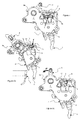
- the piece shown is a flange (1) with a protuberance (2) forming the obstacle which is the heart of the invention, a piece which is pressed against a portion of the handle and the lock.
- a flange (1) With reference to the figure 1 , the piece shown is a flange (1) with a protuberance (2) forming the obstacle which is the heart of the invention, a piece which is pressed against a portion of the handle and the lock.
- Such lock mainly comprises three elements, a link (3) and a trigger assembly (4) / contact carrier (5) carrying the movable contact (6), the assembly forming a toggle.
- the trigger (4) is visible in figure 2 , having a recess (14) forming clearance for its free movement relative to the obstacle (2) placed on the flange (1).
- the invention does not relate to the operation of the lock itself, it will not be detailed in the following. Only aspects / phases of interest within the meaning of the invention will be explained. Thus, such a clearance (14) is for example not necessary on a trigger of a traditional lock operating without the system of the invention.
- this flange (1) is however necessary for the explanation which corresponds to the figure 4 , in which the reverse manipulation is performed: the handle (8) is controlled so that the contacts (6, 7) are spaced from each other, so as to open the line.
- the path t followed by the end (3b) of the rod (3) is strictly identical to the displacement corresponding to the closure of the contacts as illustrated in FIG. Figures 3a and 3b but in the opposite direction.
- the equilibrium link (3) / trigger (4) / contact carrier (5) is retained, the operation is simply reversed with respect to the arming phase described above.
- the protuberance (2) constituting the obstacle set up according to the invention does not interfere with the path t, the end (3b) of the rod (3) being too low.
- a magnetic or thermal actuator exerts an action on the trigger (4), resulting in the rupture of the equilibrium link (3) / trigger (4) / contact carrier (5).
- the rod (3), and in particular its end (3b) is ejected upwards, as appears in figure 5a .
- the contact carrier return spring (5) recalls the trigger assembly (4) / contact carrier (5) in open contact position (6, 7).
- return means (not visible) attached to the handle (8) tend to recall the entire handle (8) / link (3) in the position contacts (6, 7) open.
- the return means respectively of the contact-holder assembly (5) / trigger (4) and of the handle (8) / rod (3) assembly are provided in such a way that their speed of movement is not the same. even. It is indeed quite fundamental that the contacts (6, 7) deviate at a high speed, whereas the return of the handle (8) / link (3) in open contacts position does not need to be fast. Their return is therefore always after the trigger assembly (4) / contact carrier (5).
- the protuberance (2) is provided in a flexible material, so that the manipulation of the handle (8) in the direction of the arrow F 'is possible by bending said protuberance (2), which deforms and lets the rod pass (3) in the direction of the trigger assembly (4) / contact carrier (5), so that the end (3b) is inserted between the spout (10) and the protrusion (9) to recover its place and reform the initial equilibrium link (3) / trigger (4) / contact carrier (5).
- the figure 5b shows that the end (3b) is actually retained by the protuberance (2) and the protrusion (9), located opposite one another: we could very well consider that the deformation of the obstacle that they together constitute either supported by said protrusion (9), then provided elastically deformable material, or by the protuberance (2) and the protrusion (9) together.
Landscapes
- Switch Cases, Indication, And Locking (AREA)
- Breakers (AREA)
Claims (7)
- Elektrisches Leitungsschutzgerät vom Typ Trennschalter, umfassend mindestens ein Paar von festen (7) bzw. beweglichen (6) Kontakte, einen Hebel (8) zur Steuerung der Kontakte (6, 7) zwischen einer ersten Abstandsposition und einer zweiten Kontaktposition, wobei der Hebel (8) mit dem beweglichen Kontakt (6) mit Hilfe eines mechanischen Schlosses verbunden ist, das auf einem Kippschalter basiert, umfassend einerseits eine Stange (3) und andererseits eine Einheit, die gegen Rückstellmittel schwenkt, und umfassend einen beweglichen Kontaktträger (5) und einen Auslöser (4), die in relativer Drehung montiert sind, wobei der Auslöser (4) mit mindestens einem Aktuator zusammenwirkt, der geeignet ist, einen elektrischen Fehler auf der Leitung wiederzugeben, wobei eines der Enden (3a) der Stange (3) drehbar an der Peripherie des Hebels (8) montiert ist, und sich das andere Ende (3b) im Gleichgewicht an einer Ausstülpung (9) des Kontaktträgers (5) in Anlage befindet und durch eine Nase (10) des Auslösers (4) gehalten wird, wobei eine Betätigung des Auslösers (4) zu seiner Drehung in Bezug zum Kontaktträger (5) und zum Kippen des Schlosses unter der Wirkung der Rückstellmittel durch Aufhebung des Gleichgewichts führt, was zur Freigabe des Endes (3b) der Stange (3) über die Ausstülpung (9) hinaus in Bezug zur Drehachse der Einheit Auslöser (4)/Kontaktträger (5) führt, wobei Rückstellmittel, die mit dem Hebel (8) verbunden sind, die Stange (3) und ihr freigegebenes Ende (3b) zu der Drehachse des Hebels (8) hin und entlang einer Bahn außerhalb der Einheit zurückführen, dadurch gekennzeichnet, dass es ein Hindernis (2) umfasst, das auf der Bahn angeordnet ist und die Einheit Stange (3)/Hebel (8) in einer Zwischenposition feststellt, die das Auslösen des Schlosses in Folge eines elektrischen Fehlers auf einer Leitung anzeigt, wobei das Hindernis (2) zumindest teilweise einziehbar und/oder verformbar ist, wenn die auf den Hebel (8) ausgeübte Kraft größer als die Kraft ist, die von den Rückstellmitteln des Hebels (8) kommt, und dass das Hindernis einen Vorsprung (2) umfasst, der sich zum Inneren der Vorderseite des Gehäuses des Geräts, aus der der Hebel (8) herausragt, erstreckt, oder sich zum Inneren einer Wand erstreckt, die im Wesentlichen parallel zu und in der Nähe der Vorderseite eines Elements vom Typ Flansch (1), der mit dem Gehäuse verbunden ist und mit dem freigegebenen Ende (3b) der Stange (3) zusammenwirkt, ausgerichtet ist.
- Elektrisches Leitungsschutzgerät nach dem vorhergehenden Anspruch, dadurch gekennzeichnet, dass mindestens ein Teil des Hindernisses (2) aus einem biegsamen Material vorgesehen ist, damit die vollständige Drehung des Hebels (8) dieses elastisch mit Hilfe des freigegebenen Endes (3b) der Stange (3) verformt.
- Elektrisches Leitungsschutzgerät nach Anspruch 1, dadurch gekennzeichnet, dass der Vorsprung (2) aus einem biegsamen Material hergestellt ist.
- Elektrisches Leitungsschutzgerät nach einem der vorhergehenden Ansprüche, dadurch gekennzeichnet, dass die Wand, die parallel zur Vorderseite eines Elements vom Typ Flansch (1), der mit dem Gehäuse verbunden ist, ausgerichtet ist, zumindest in der Befestigungszone des Vorsprungs (2) biegsam ist.
- Elektrisches Leitungsschutzgerät nach einem der vorhergehenden Ansprüche, dadurch gekennzeichnet, dass das Hindernis den Vorsprung (2) umfasst, der mit der Ausstülpung (9) des Kontaktträgers (5) zusammenwirkt.
- Elektrisches Leitungsschutzgerät nach einem der vorhergehenden Ansprüche, dadurch gekennzeichnet, dass die Ausstülpung (9) des Kontaktträgers (5) biegsam ist.
- Elektrisches Leitungsschutzgerät nach einem der vorhergehenden Ansprüche, dadurch gekennzeichnet, dass die Nase (10) des Auslösers (4) eine Ausnehmung (14) umfasst, die eine Aussparung bildet, die in einem Abschnitt vorgesehen ist, der geeignet ist, mit dem Vorsprung (2) während ihrer relativen Bewegung zu interferieren.
Applications Claiming Priority (1)
| Application Number | Priority Date | Filing Date | Title |
|---|---|---|---|
| FR1101340A FR2974664B1 (fr) | 2011-04-29 | 2011-04-29 | Indicateur de declenchement de defaut par la position de la manette |
Publications (2)
| Publication Number | Publication Date |
|---|---|
| EP2518752A1 EP2518752A1 (de) | 2012-10-31 |
| EP2518752B1 true EP2518752B1 (de) | 2016-09-28 |
Family
ID=46051653
Family Applications (1)
| Application Number | Title | Priority Date | Filing Date |
|---|---|---|---|
| EP12305477.7A Active EP2518752B1 (de) | 2011-04-29 | 2012-04-27 | Anzeiger der Störungsauslösung durch die Position des Handsteuerhebels |
Country Status (2)
| Country | Link |
|---|---|
| EP (1) | EP2518752B1 (de) |
| FR (1) | FR2974664B1 (de) |
Cited By (1)
| Publication number | Priority date | Publication date | Assignee | Title |
|---|---|---|---|---|
| CN110970274A (zh) * | 2019-12-23 | 2020-04-07 | 国网江苏省电力有限公司滨海县供电分公司 | 一种小型断路器 |
Families Citing this family (3)
| Publication number | Priority date | Publication date | Assignee | Title |
|---|---|---|---|---|
| CN103346047B (zh) * | 2013-05-30 | 2016-03-30 | 浙江天正电气股份有限公司 | 一种带故障脱扣指示装置的小型断路器 |
| CN103413732A (zh) * | 2013-08-29 | 2013-11-27 | 温州罗格朗电器有限公司 | 一种断路器的操作机构 |
| CN104733253B (zh) * | 2015-03-23 | 2017-03-22 | 厦门宏发开关设备有限公司 | 一种具有三色显示的开关断路器 |
Family Cites Families (5)
| Publication number | Priority date | Publication date | Assignee | Title |
|---|---|---|---|---|
| US2828388A (en) * | 1955-11-02 | 1958-03-25 | Fed Pacific Electric Co | Circuit breakers |
| US3183325A (en) * | 1961-05-03 | 1965-05-11 | Fed Pacific Electric Co | Trip indicating circuit breakers |
| EP0338930A1 (de) * | 1988-04-22 | 1989-10-25 | Hager Electro S.A. | Lastschalter oder Differential-Lastschalter |
| DE3825443A1 (de) * | 1988-07-27 | 1990-02-01 | Asea Brown Boveri | Elektrisches schaltgeraet |
| FR2649826B1 (fr) * | 1989-07-11 | 1995-11-24 | Merlin Gerin | Mecanisme de commande pour disjoncteur electrique |
-
2011
- 2011-04-29 FR FR1101340A patent/FR2974664B1/fr not_active Expired - Fee Related
-
2012
- 2012-04-27 EP EP12305477.7A patent/EP2518752B1/de active Active
Cited By (2)
| Publication number | Priority date | Publication date | Assignee | Title |
|---|---|---|---|---|
| CN110970274A (zh) * | 2019-12-23 | 2020-04-07 | 国网江苏省电力有限公司滨海县供电分公司 | 一种小型断路器 |
| CN110970274B (zh) * | 2019-12-23 | 2022-03-08 | 国网江苏省电力有限公司滨海县供电分公司 | 一种小型断路器 |
Also Published As
| Publication number | Publication date |
|---|---|
| EP2518752A1 (de) | 2012-10-31 |
| FR2974664B1 (fr) | 2013-12-20 |
| FR2974664A1 (fr) | 2012-11-02 |
Similar Documents
| Publication | Publication Date | Title |
|---|---|---|
| EP1542253B1 (de) | Anzeigeeinrichtung einer Auslöseeinrichtung eines elektrischen Schutzgeräts | |
| EP1975971B1 (de) | Bedienungsvorrichtung eines elektrischen Sicherungsgeräts und elektrisches Sicherungsgerät, das sie umfasst | |
| EP2460172B1 (de) | Drehbares steuersystem für einen stromschutzschalter | |
| EP2518752B1 (de) | Anzeiger der Störungsauslösung durch die Position des Handsteuerhebels | |
| EP1743346B1 (de) | Überspannungsschutzeinrichtung mit lichtbogenlöschelementen | |
| EP2733720B1 (de) | Thermomagnetischer Auslöser zur Auslösung eines Mehrphasen-Überlastschalters | |
| EP3499541B1 (de) | Elektrisches schutzgerät, das ein pyrotechnisches betätigungssystem umfasst | |
| FR2931998A1 (fr) | Dispositif de commande d'un appareil de coupure electrique comportant un dispositif de signalisation de la soudure des contacts, et appareil de coupure electrique comportant un tel dispositif | |
| EP2975628A1 (de) | Vorrichtung zur signalisierung einer elektrischen störung in einem elektrischen schutzgerät, und gerät, das eine solche vorrichtung umfasst | |
| EP2377139B1 (de) | Vorrichtung zur fernbetätigung und damit versehener schutzschalter | |
| EP2717284B1 (de) | Bedienungsvorrichtung eines elektrischen Schutzschaltgeräts, und diese umfassendes elektrisches Schutzschaltgerät | |
| EP0657909A1 (de) | Elektrischer Schalter mit Fehlerauslosung | |
| EP1703533B1 (de) | Anzeigesystem für magnetische Fehler | |
| FR3051593B1 (fr) | Dispositif de signalisation d'un defaut electrique dans un appareil de protection electrique, et appareil de protection electrique comportant un tel dispositif. | |
| EP2359379B1 (de) | Steuermechanismus für eine fernbediente abschneideeinrichtung, abschneideeinrichtung und fernbediente unterbrecherschaltung mit einem solchen mechanismus | |
| FR2940517A1 (fr) | Dispositif de telecommande pourvu de moyens de signalisation et disjoncteur telecommande equipe d'un tel dispositif de telecommande | |
| FR2959594A1 (fr) | Dispositif de telecommande et disjoncteur telecommande equipe d'un tel dispositif. | |
| EP2642502B1 (de) | Auslöseblock für elektrisches Sicherungsgerät, und mit einem solchen Block ausgestattetes elektrisches Sicherungsgerät | |
| FR2940515A1 (fr) | Dispositif de telecommande et disjoncteur telecommande equipe d'un tel dispositif | |
| EP2758977A1 (de) | Stromleitungsschutzvorrichtung mit anzeige eines elektrischen fehlers in der leitung | |
| EP3134910B1 (de) | Vorrichtung mit beweglichem kontakt ohne leitfähige litze | |
| EP1747564B1 (de) | Überspannungs-schutzeinrichtung mit einem verbesserten display-system | |
| FR2462017A1 (fr) | Coupe-circuit comportant un moyen de signalisation de precoupure, de fusion de cartouche ou d'absence de cartouche | |
| EP0327460A1 (de) | Elektrischer Schalter mit automatischer Ausschaltung, insbesondere Differentialschutz | |
| EP3029703A1 (de) | Schutzschalter, bevorzugt fehlerstromschutzschalter |
Legal Events
| Date | Code | Title | Description |
|---|---|---|---|
| PUAI | Public reference made under article 153(3) epc to a published international application that has entered the european phase |
Free format text: ORIGINAL CODE: 0009012 |
|
| AK | Designated contracting states |
Kind code of ref document: A1 Designated state(s): AL AT BE BG CH CY CZ DE DK EE ES FI FR GB GR HR HU IE IS IT LI LT LU LV MC MK MT NL NO PL PT RO RS SE SI SK SM TR |
|
| AX | Request for extension of the european patent |
Extension state: BA ME |
|
| 17P | Request for examination filed |
Effective date: 20130411 |
|
| GRAP | Despatch of communication of intention to grant a patent |
Free format text: ORIGINAL CODE: EPIDOSNIGR1 |
|
| RIC1 | Information provided on ipc code assigned before grant |
Ipc: H01H 71/52 20060101ALI20160323BHEP Ipc: H01H 71/04 20060101AFI20160323BHEP |
|
| INTG | Intention to grant announced |
Effective date: 20160419 |
|
| GRAS | Grant fee paid |
Free format text: ORIGINAL CODE: EPIDOSNIGR3 |
|
| GRAA | (expected) grant |
Free format text: ORIGINAL CODE: 0009210 |
|
| AK | Designated contracting states |
Kind code of ref document: B1 Designated state(s): AL AT BE BG CH CY CZ DE DK EE ES FI FR GB GR HR HU IE IS IT LI LT LU LV MC MK MT NL NO PL PT RO RS SE SI SK SM TR |
|
| REG | Reference to a national code |
Ref country code: GB Ref legal event code: FG4D Free format text: NOT ENGLISH |
|
| REG | Reference to a national code |
Ref country code: CH Ref legal event code: EP |
|
| REG | Reference to a national code |
Ref country code: AT Ref legal event code: REF Ref document number: 833378 Country of ref document: AT Kind code of ref document: T Effective date: 20161015 |
|
| REG | Reference to a national code |
Ref country code: IE Ref legal event code: FG4D Free format text: LANGUAGE OF EP DOCUMENT: FRENCH |
|
| REG | Reference to a national code |
Ref country code: DE Ref legal event code: R096 Ref document number: 602012023472 Country of ref document: DE |
|
| REG | Reference to a national code |
Ref country code: CH Ref legal event code: NV Representative=s name: DR. GRAF AND PARTNER AG INTELLECTUAL PROPERTY, CH |
|
| REG | Reference to a national code |
Ref country code: LT Ref legal event code: MG4D |
|
| PG25 | Lapsed in a contracting state [announced via postgrant information from national office to epo] |
Ref country code: LT Free format text: LAPSE BECAUSE OF FAILURE TO SUBMIT A TRANSLATION OF THE DESCRIPTION OR TO PAY THE FEE WITHIN THE PRESCRIBED TIME-LIMIT Effective date: 20160928 Ref country code: RS Free format text: LAPSE BECAUSE OF FAILURE TO SUBMIT A TRANSLATION OF THE DESCRIPTION OR TO PAY THE FEE WITHIN THE PRESCRIBED TIME-LIMIT Effective date: 20160928 Ref country code: HR Free format text: LAPSE BECAUSE OF FAILURE TO SUBMIT A TRANSLATION OF THE DESCRIPTION OR TO PAY THE FEE WITHIN THE PRESCRIBED TIME-LIMIT Effective date: 20160928 Ref country code: FI Free format text: LAPSE BECAUSE OF FAILURE TO SUBMIT A TRANSLATION OF THE DESCRIPTION OR TO PAY THE FEE WITHIN THE PRESCRIBED TIME-LIMIT Effective date: 20160928 Ref country code: NO Free format text: LAPSE BECAUSE OF FAILURE TO SUBMIT A TRANSLATION OF THE DESCRIPTION OR TO PAY THE FEE WITHIN THE PRESCRIBED TIME-LIMIT Effective date: 20161228 |
|
| REG | Reference to a national code |
Ref country code: NL Ref legal event code: MP Effective date: 20160928 |
|
| REG | Reference to a national code |
Ref country code: AT Ref legal event code: MK05 Ref document number: 833378 Country of ref document: AT Kind code of ref document: T Effective date: 20160928 |
|
| PG25 | Lapsed in a contracting state [announced via postgrant information from national office to epo] |
Ref country code: LV Free format text: LAPSE BECAUSE OF FAILURE TO SUBMIT A TRANSLATION OF THE DESCRIPTION OR TO PAY THE FEE WITHIN THE PRESCRIBED TIME-LIMIT Effective date: 20160928 Ref country code: GR Free format text: LAPSE BECAUSE OF FAILURE TO SUBMIT A TRANSLATION OF THE DESCRIPTION OR TO PAY THE FEE WITHIN THE PRESCRIBED TIME-LIMIT Effective date: 20161229 Ref country code: NL Free format text: LAPSE BECAUSE OF FAILURE TO SUBMIT A TRANSLATION OF THE DESCRIPTION OR TO PAY THE FEE WITHIN THE PRESCRIBED TIME-LIMIT Effective date: 20160928 Ref country code: SE Free format text: LAPSE BECAUSE OF FAILURE TO SUBMIT A TRANSLATION OF THE DESCRIPTION OR TO PAY THE FEE WITHIN THE PRESCRIBED TIME-LIMIT Effective date: 20160928 |
|
| REG | Reference to a national code |
Ref country code: FR Ref legal event code: PLFP Year of fee payment: 6 |
|
| PG25 | Lapsed in a contracting state [announced via postgrant information from national office to epo] |
Ref country code: RO Free format text: LAPSE BECAUSE OF FAILURE TO SUBMIT A TRANSLATION OF THE DESCRIPTION OR TO PAY THE FEE WITHIN THE PRESCRIBED TIME-LIMIT Effective date: 20160928 Ref country code: EE Free format text: LAPSE BECAUSE OF FAILURE TO SUBMIT A TRANSLATION OF THE DESCRIPTION OR TO PAY THE FEE WITHIN THE PRESCRIBED TIME-LIMIT Effective date: 20160928 |
|
| PG25 | Lapsed in a contracting state [announced via postgrant information from national office to epo] |
Ref country code: PT Free format text: LAPSE BECAUSE OF FAILURE TO SUBMIT A TRANSLATION OF THE DESCRIPTION OR TO PAY THE FEE WITHIN THE PRESCRIBED TIME-LIMIT Effective date: 20170130 Ref country code: SM Free format text: LAPSE BECAUSE OF FAILURE TO SUBMIT A TRANSLATION OF THE DESCRIPTION OR TO PAY THE FEE WITHIN THE PRESCRIBED TIME-LIMIT Effective date: 20160928 Ref country code: SK Free format text: LAPSE BECAUSE OF FAILURE TO SUBMIT A TRANSLATION OF THE DESCRIPTION OR TO PAY THE FEE WITHIN THE PRESCRIBED TIME-LIMIT Effective date: 20160928 Ref country code: AT Free format text: LAPSE BECAUSE OF FAILURE TO SUBMIT A TRANSLATION OF THE DESCRIPTION OR TO PAY THE FEE WITHIN THE PRESCRIBED TIME-LIMIT Effective date: 20160928 Ref country code: ES Free format text: LAPSE BECAUSE OF FAILURE TO SUBMIT A TRANSLATION OF THE DESCRIPTION OR TO PAY THE FEE WITHIN THE PRESCRIBED TIME-LIMIT Effective date: 20160928 Ref country code: IS Free format text: LAPSE BECAUSE OF FAILURE TO SUBMIT A TRANSLATION OF THE DESCRIPTION OR TO PAY THE FEE WITHIN THE PRESCRIBED TIME-LIMIT Effective date: 20170128 Ref country code: BG Free format text: LAPSE BECAUSE OF FAILURE TO SUBMIT A TRANSLATION OF THE DESCRIPTION OR TO PAY THE FEE WITHIN THE PRESCRIBED TIME-LIMIT Effective date: 20161228 Ref country code: CZ Free format text: LAPSE BECAUSE OF FAILURE TO SUBMIT A TRANSLATION OF THE DESCRIPTION OR TO PAY THE FEE WITHIN THE PRESCRIBED TIME-LIMIT Effective date: 20160928 Ref country code: PL Free format text: LAPSE BECAUSE OF FAILURE TO SUBMIT A TRANSLATION OF THE DESCRIPTION OR TO PAY THE FEE WITHIN THE PRESCRIBED TIME-LIMIT Effective date: 20160928 |
|
| REG | Reference to a national code |
Ref country code: DE Ref legal event code: R097 Ref document number: 602012023472 Country of ref document: DE |
|
| PG25 | Lapsed in a contracting state [announced via postgrant information from national office to epo] |
Ref country code: DK Free format text: LAPSE BECAUSE OF FAILURE TO SUBMIT A TRANSLATION OF THE DESCRIPTION OR TO PAY THE FEE WITHIN THE PRESCRIBED TIME-LIMIT Effective date: 20160928 |
|
| PLBE | No opposition filed within time limit |
Free format text: ORIGINAL CODE: 0009261 |
|
| STAA | Information on the status of an ep patent application or granted ep patent |
Free format text: STATUS: NO OPPOSITION FILED WITHIN TIME LIMIT |
|
| 26N | No opposition filed |
Effective date: 20170629 |
|
| PG25 | Lapsed in a contracting state [announced via postgrant information from national office to epo] |
Ref country code: SI Free format text: LAPSE BECAUSE OF FAILURE TO SUBMIT A TRANSLATION OF THE DESCRIPTION OR TO PAY THE FEE WITHIN THE PRESCRIBED TIME-LIMIT Effective date: 20160928 |
|
| GBPC | Gb: european patent ceased through non-payment of renewal fee |
Effective date: 20170427 |
|
| REG | Reference to a national code |
Ref country code: IE Ref legal event code: MM4A |
|
| PG25 | Lapsed in a contracting state [announced via postgrant information from national office to epo] |
Ref country code: MC Free format text: LAPSE BECAUSE OF FAILURE TO SUBMIT A TRANSLATION OF THE DESCRIPTION OR TO PAY THE FEE WITHIN THE PRESCRIBED TIME-LIMIT Effective date: 20160928 |
|
| PG25 | Lapsed in a contracting state [announced via postgrant information from national office to epo] |
Ref country code: GB Free format text: LAPSE BECAUSE OF NON-PAYMENT OF DUE FEES Effective date: 20170427 Ref country code: LU Free format text: LAPSE BECAUSE OF NON-PAYMENT OF DUE FEES Effective date: 20170427 |
|
| REG | Reference to a national code |
Ref country code: BE Ref legal event code: MM Effective date: 20170430 |
|
| REG | Reference to a national code |
Ref country code: FR Ref legal event code: PLFP Year of fee payment: 7 |
|
| PG25 | Lapsed in a contracting state [announced via postgrant information from national office to epo] |
Ref country code: IE Free format text: LAPSE BECAUSE OF NON-PAYMENT OF DUE FEES Effective date: 20170427 |
|
| PG25 | Lapsed in a contracting state [announced via postgrant information from national office to epo] |
Ref country code: BE Free format text: LAPSE BECAUSE OF NON-PAYMENT OF DUE FEES Effective date: 20170430 |
|
| PG25 | Lapsed in a contracting state [announced via postgrant information from national office to epo] |
Ref country code: MT Free format text: LAPSE BECAUSE OF FAILURE TO SUBMIT A TRANSLATION OF THE DESCRIPTION OR TO PAY THE FEE WITHIN THE PRESCRIBED TIME-LIMIT Effective date: 20160928 |
|
| PG25 | Lapsed in a contracting state [announced via postgrant information from national office to epo] |
Ref country code: AL Free format text: LAPSE BECAUSE OF FAILURE TO SUBMIT A TRANSLATION OF THE DESCRIPTION OR TO PAY THE FEE WITHIN THE PRESCRIBED TIME-LIMIT Effective date: 20160928 |
|
| PG25 | Lapsed in a contracting state [announced via postgrant information from national office to epo] |
Ref country code: HU Free format text: LAPSE BECAUSE OF FAILURE TO SUBMIT A TRANSLATION OF THE DESCRIPTION OR TO PAY THE FEE WITHIN THE PRESCRIBED TIME-LIMIT; INVALID AB INITIO Effective date: 20120427 |
|
| PG25 | Lapsed in a contracting state [announced via postgrant information from national office to epo] |
Ref country code: CY Free format text: LAPSE BECAUSE OF NON-PAYMENT OF DUE FEES Effective date: 20160928 |
|
| PG25 | Lapsed in a contracting state [announced via postgrant information from national office to epo] |
Ref country code: MK Free format text: LAPSE BECAUSE OF FAILURE TO SUBMIT A TRANSLATION OF THE DESCRIPTION OR TO PAY THE FEE WITHIN THE PRESCRIBED TIME-LIMIT Effective date: 20160928 |
|
| PG25 | Lapsed in a contracting state [announced via postgrant information from national office to epo] |
Ref country code: TR Free format text: LAPSE BECAUSE OF FAILURE TO SUBMIT A TRANSLATION OF THE DESCRIPTION OR TO PAY THE FEE WITHIN THE PRESCRIBED TIME-LIMIT Effective date: 20160928 |
|
| P01 | Opt-out of the competence of the unified patent court (upc) registered |
Effective date: 20230606 |
|
| PGFP | Annual fee paid to national office [announced via postgrant information from national office to epo] |
Ref country code: DE Payment date: 20240429 Year of fee payment: 13 |
|
| PGFP | Annual fee paid to national office [announced via postgrant information from national office to epo] |
Ref country code: CH Payment date: 20240501 Year of fee payment: 13 |
|
| PGFP | Annual fee paid to national office [announced via postgrant information from national office to epo] |
Ref country code: IT Payment date: 20240422 Year of fee payment: 13 Ref country code: FR Payment date: 20240425 Year of fee payment: 13 |
|
| REG | Reference to a national code |
Ref country code: DE Ref legal event code: R119 Ref document number: 602012023472 Country of ref document: DE |
|
| REG | Reference to a national code |
Ref country code: CH Ref legal event code: H13 Free format text: ST27 STATUS EVENT CODE: U-0-0-H10-H13 (AS PROVIDED BY THE NATIONAL OFFICE) Effective date: 20251125 |
|
| PG25 | Lapsed in a contracting state [announced via postgrant information from national office to epo] |
Ref country code: DE Free format text: LAPSE BECAUSE OF NON-PAYMENT OF DUE FEES Effective date: 20251104 |
|
| PG25 | Lapsed in a contracting state [announced via postgrant information from national office to epo] |
Ref country code: FR Free format text: LAPSE BECAUSE OF NON-PAYMENT OF DUE FEES Effective date: 20250430 |
|
| PG25 | Lapsed in a contracting state [announced via postgrant information from national office to epo] |
Ref country code: CH Free format text: LAPSE BECAUSE OF NON-PAYMENT OF DUE FEES Effective date: 20250430 |
|
| PG25 | Lapsed in a contracting state [announced via postgrant information from national office to epo] |
Ref country code: IT Free format text: LAPSE BECAUSE OF NON-PAYMENT OF DUE FEES Effective date: 20250427 |