EP1143569A2 - Connecteur électrique - Google Patents
Connecteur électrique Download PDFInfo
- Publication number
- EP1143569A2 EP1143569A2 EP01302124A EP01302124A EP1143569A2 EP 1143569 A2 EP1143569 A2 EP 1143569A2 EP 01302124 A EP01302124 A EP 01302124A EP 01302124 A EP01302124 A EP 01302124A EP 1143569 A2 EP1143569 A2 EP 1143569A2
- Authority
- EP
- European Patent Office
- Prior art keywords
- housing
- detecting member
- stopping
- hood
- legs
- Prior art date
- Legal status (The legal status is an assumption and is not a legal conclusion. Google has not performed a legal analysis and makes no representation as to the accuracy of the status listed.)
- Withdrawn
Links
- 238000005452 bending Methods 0.000 claims description 28
- 238000003780 insertion Methods 0.000 claims description 3
- 230000037431 insertion Effects 0.000 claims description 3
- 241000282979 Alces alces Species 0.000 abstract 1
- 230000000717 retained effect Effects 0.000 description 6
- 238000012423 maintenance Methods 0.000 description 3
- 238000000465 moulding Methods 0.000 description 3
- 239000002184 metal Substances 0.000 description 1
- 230000001105 regulatory effect Effects 0.000 description 1
Images


Classifications
-
- H—ELECTRICITY
- H01—ELECTRIC ELEMENTS
- H01R—ELECTRICALLY-CONDUCTIVE CONNECTIONS; STRUCTURAL ASSOCIATIONS OF A PLURALITY OF MUTUALLY-INSULATED ELECTRICAL CONNECTING ELEMENTS; COUPLING DEVICES; CURRENT COLLECTORS
- H01R13/00—Details of coupling devices of the kinds covered by groups H01R12/70 or H01R24/00 - H01R33/00
- H01R13/64—Means for preventing incorrect coupling
- H01R13/641—Means for preventing incorrect coupling by indicating incorrect coupling; by indicating correct or full engagement
Definitions
- the present invention relates to an electrical connector, particularly a connector provided with a fitting detecting function.
- JP 11-26089 One example of a connector provided with a fitting detecting member for checking the fitting state of male and female connector housings is desribed in JP 11-26089.
- This connector has a locking arm provided on an upper face of a female housing that fits within a hood of a male connector, this locking arm engaging with a locking member provided in the male connector.
- a pair of protecting walls protrude from left and right sides of the locking arm, and a detecting member is attached to the posterior of the locking arm. The detecting member can be inserted from a waiting position at the exterior of the locking arm to an operating position within a bending space of the locking arm.
- the detecting member makes contact with the locking arm, thereby preventing further movement of the detecting member towards the operating position. That is, the fitting state of the two housings can be detected according to whether the detecting member moves or not.
- a pair of detecting arms extend towards the anterior from the detecting member.
- the anterior ends of these resilient stopping arms engage with a posterior end face of the protecting wall, thereby preventing the detecting member from moving from the waiting position towards the anterior.
- Outwardly extending protrusions (extending to the exterior of the protecting wall) are provided on side faces of the resilient stopping arm. Inner faces of the hood of the male housing engage with the outwardly extending protrusions while the two housings are being fitted together, thereby bending the detecting arms inwards and releasing them from their retained state with the protecting wall. This allows the detecting member to be pushed in towards the operating position.
- the detecting arms After the detecting member has been pushed in to the operating position, the detecting arms are maintained in a bent state whereby the outwardly extending protrusions make contact with the inner faces of the hood, the resilient force of the detecting arms preventing the detecting member from leaving the operating position.
- the resilient stopping arm While the connector is being used after the fitting operation has taken place, the resilient stopping arm remains in a bent state. If the resilient stopping arm remains in this state for a long period, the creep phenomenon may affect the resilience thereof, and the resilient stopping arm may lose its resilience.
- the present invention has taken the above problem into consideration, and aims to present a connector wherein a resilient stopping arm does not lose its resilience.
- a connector comprising a first housing having a hood and a second housing insertable within said hood in a fitting direction to a fully inserted condition, the second housing having a bendable latching arm extending in the fitting direction and engageable with a latch member of said first housing in the fully inserted condition, and the connector further including a detecting member movable from a waiting position to an advanced condition in which said detecting member enters a bending space of said latching arm to prevent bending movement thereof, wherein said second housing has upstanding side walls extending in the fitting direction on either side of said latching arm and at a distance therefrom, said detecting member having two resilient legs extending respectively between said latching arm and a corresponding side wall, each leg having an outwardly extending protrusion engageable through a corresponding aperture of a said respective side wall and for maintaining said detecting member in the waiting position, said hood being adapted to engage said protrusions on insertion of said second housing, and to force said protrusions inwards
- the recesses of the hood comprises channels open to the rear side, thus permitting moulding of the first housing without the use of removable inserts.
- associated contact surfaces of the protrusion, first housing and second housing are chamfered or tapered sufficiently to ensure good operability.
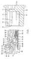
- a connector of the present embodiment is formed from a male connector housing 10 that fits with a female connector housing 20.
- a fitting detecting member 40 for ascertaining the fitting state of the connector, is attached to the female housing 20. Fitting face sides of the two housings 10 and 20 will hereafter be considered as the anterior sides.
- the male housing 10 is provided with a wall member 11 and a cylindrical hood 12, this hood 12 protruding towards the anterior from the wall member 11.
- the female housing 20 can be fitted within the hood 12.
- a hook-shaped locking member 14 protrudes downwards from an upper portion of the hood 12.
- a resilient locking arm 26 of the female housing 20 engages with this locking member 14.
- the female housing 20 has four cavities 21 aligned therein in positions corresponding to the male terminal fittings 13.
- a female terminal fitting 22 can be housed within each cavity 21, each female terminal fitting 22 being crimped from the posterior to the end of an electric wire W.
- a step-shaped stopping member 23 is formed at an upper face of each cavity 21.
- Metal lances 22A formed by cutting into upper faces of the female terminal fittings engage with the stopping members 23.
- a retainer attachment hole 24 intersects with each cavity 21 of the female housing 20, a retainer (not shown) being attached through these retainer attachment holes 24 and retaining the female terminal fittings in an unremovable manner.
- a posterior end portion of the female housing 20 protrudes to the posterior relative to the upper portion (relative to the figures) of the cavities 21.
- a pair of step-shaped fitting operating members 25 protrude from left and right side faces (relative to Figure 3) of the female housing 20, the female housing 20 being pushed into the male housing 10 by means of these fitting operating members 25.
- the cantilevered locking arm 26 protrudes upwards from an upper face of the female housing 20, from a central location relative to the width-wide direction thereof.
- the locking arm 26 has its base end at the anterior end of the female housing 20 and an arm portion thereof extends towards the posterior from this base end.
- a posterior end of the locking arm 26 is located at a specified distance inwards from the posterior end of the upper face of the female housing 20.
- the locking arm 26 is capable of bending, the arm portion thereof bending into a bending space S located below this arm portion.
- a posterior lower face of the arm portion grows thinner towards the posterior, forming a tapered face 26A.
- a locking protrusion 27 protrudes from the upper face of the locking arm 26 from a central location relative to the lengthwise direction thereof. When the two housings 10 and 20 are correctly fitted together, this locking protrusion 27 engages with the locking member 14 of the male housing 10.
- An anterior face of the locking protrusion 27 is a tapered face.
- a pushing operating member 28 protrudes from the posterior end of the upper face of the locking arm 26. Pushing this pushing operating member 28 from above causes the locking arm 26 to bend to a release position.
- a pair of side walls 29 are formed to the sides of the locking arm 26 on the upper face of the female housing 20. These side walls 29 protrude upwards and extend along the entire length of the female housing 20. Spaces having a specified width are maintained between inner faces of these side walls 29 and the locking arm 26. Outer faces of the side walls 29 form a unified face with outer side faces of the female housing 20. When the two housings 10 and 20 are being fitted together, inner side faces of the hood 12 of the male housing 10 slide against the outer faces of the side walls 29.
- a pair of protecting ribs 30 protrude upwards from upper faces of the side walls 29 at locations adjacent to the pushing operating member 28 of the locking arm 26. These protecting ribs 30 rise to the same height as the pushing operating member 28 and prevent the locking arm 26 from accidentally being bent.
- attachment grooves 31 are open to the posterior of the female housing 20.
- Ceiling faces of the attachment grooves 31 have approximately the same height as the lower face of the locking arm 26.
- Lower faces of the attachment grooves 31 adjoin the upper face of the female housing 20.
- anterior end faces of the attachment grooves 31 are located at approximately the same position as an anterior end of the locking protrusion 27 of the locking arm 26.
- the side walls 29 extend in to the anterior part of the attachment grooves 31.
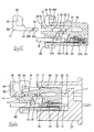
- the detecting member 40 is attached from the posterior to the upper face of the female housing 20 via the attachment grooves 31. As shown in Figure 1, the detecting member 40 is attached in a waiting position to the posterior of the locking arm 26 (that is, to the exterior of the bending space S). As shown in Figure 10, after the two housings 10 and 20 have been fitted together, the detecting member 40 is inserted into the bending space S and is thus moved to an operating position, whereby it is capable of regulating the bending of the locking arm 26.
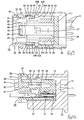
- the detecting member 40 is provided with a rectangular plate-shaped main body 41 and a pair of resilient stopping legs 42 that extend towards the anterior from both side edges of an anterior face of this main body 41.
- the main body 41 is slightly smaller than the heights of the bending space S of the locking arm 26 and the attachment grooves 31.
- the width of the main body 41 is approximately the same as the distance between both side faces of the two attachment grooves 31.
- Both resilient stopping legs 42 are capable of bending inwards resiliently.
- a hook-shaped protrusion extends outwards from an anterior end portion of each resilient stopping leg 42.
- the distance between protruding anterior ends of the resilient stopping arms 42 is approximately the same as the width of the upper face of the female housing 20.
- Retaining protrusions 43 extend outwards from the outwardly protruding anterior ends of the resilient stopping legs 42.
- Anterior and posterior faces of these retaining protrusions 43 form large tapered faces 43A and small tapered faces 43B respectively.
- Side faces of the resilient stopping legs 42 form unified faces with side faces of the main body 41. As shown in Figure 5, lower faces of the resilient stopping legs 42 are level with lower faces of the main body 41, and the resilient stopping legs 42 are slightly shorter in height than the mian body 41.
- an operating member 44 for moving the detecting member 40, protrudes from a posterior end of the upper face of the mian body 41.
- This operating member 44 is plate-shaped and a posterior face thereof forms a unified face with a posterior face of the main body 41.
- a pair of protecting walls 45 protrude towards the anterior from both end portions of the operating member 44. Anterior ends of these protecting walls 45 are located somewhat towards the posterior relative to the anterior face of the main body 41. Anterior faces of the protecting walls 45 are arc shaped.
- the resilient stopping legs 42 are first bent inwards, and the anterior ends thereof are inserted into the attachment grooves 31.
- a pair of guiding grooves 32 having the same dimensions as the resilient stopping legs 42, are formed in inner side faces of the attachment grooves 31.
- the resilient stopping legs 42 are fitted into these guiding grooves 32 and make sliding contact with inner faces thereof, thereby guiding the insertion of the resilient stopping legs 42.
- both side ends of the main body 41 are inserted into the atachment grooves 31 and, as shown in Figure 1, the detecting member 40 is attached in the waiting poisition with the main body 41 being located outside the bending space S of the locking arm 26.
- a pair of temporary stopping holes 33 are provided in anterior ends of the guiding grooves 32, these temporary stopping holes 33 being open to the side outer portions of the side walls 29.
- the retaining protrusions 43 of the resilient stopping legs 42 and the hook-shaped protrusions thereof can be inserted into the temporary stopping holes 33.
- the hook-shaped protrusions of the resilient stopping legs 42 engage with anterior and posterior hole edges of the temporary stopping holes 33, thereby maintaining the detecting member 40 in a state whereby it cannot move to the anterior or posterior from the waiting position.
- the temporary stopping holes 33 have a quadrangular shape and are located at a height corresponding to the guiding grooves 32.
- anterior portions of the hole edges of the temporary stopping holes 33 (the posterior face of pillar members 35) have inward-facing tapered faces 33A formed thereon.
- the detecting member 40 When the detecting member 40 is in an attached state in the waiting position, the retaining protrusions 43 of the resilient stopping legs 42 protrude outwards from the outer face of the female housing 20. If the two housings 10 and 20 are fitted together from this state, an anterior end of the hood 12 of the male housing 10 makes contact with these retaining protrusions 43. Furthermore, the detecting member 40, in this waiting position, protrudes to the posterior for a specified distance from the posterior end of the female housing 20. When the detecting member 40 is in an attached state with the female housing 20, the two protecting walls 45 of the detecting member 40 are inserted in the spaces between the side walls 29 and the locking arm 26.
- the resilient stopping legs 42 are inserted into main stopping holes 34 that are provided in the side walls 29 at a specified distance towards the anterior from the temporary stopping holes 33.
- the main stopping holes 34 are open to the anterior of the female housing 20, and the pillar members 35 remain between these main stopping holes 34 and the temporary stopping holes 33.
- the hook-shaped protrusions of the resilient stopping legs 42 engage with posterior hole edges (anterior faces of the pillar members 35) of the main stopping holes 34, thereby preventing the detecting member 40, which is in the operating position, from moving towards the posterior.
- the posterior hole edges of the main stopping holes 34 have inwardly-inclined tapered faces 34A formed thereon.
- the portion surrounded by the operating member 44 and the protecting walls 45 of the main body 41 is inserted within the bending space S of the locking arm 26.
- the anterior end portion of the main body 41 is inserted to a position to the anterior of the tapered face 26A at the lower face of the locking arm 26.
- An anterior face of the operating member 44 makes contact with a posterior end face of the locking arm 26, thereby preventing the detecting member 40 from moving towards the anterior from the operating position.
- the protecting walls 45 are located laterally relative to side faces of the locking arm 26.
- a pair of grooves 15 are formed in the inner side faces of the hood 12 of the male housing 10. These grooves 15 are slit like, begin at a location at a specified distance towards the posterior from the anterior edge of the hood 12, and are open to the posterior of the male housing 10. The grooves 15 are located at a height corresponding to the main stopping holes 34 of the female housing 20 that has been fitted within the hood 12. The width of the grooves 15 is approximately the same as the height of the main stopping holes 34.
- the male housing 10 When the male housing 10 is to be moulded, molten plastic is injected into a mould (not shown). After the plastic has solidified, the mould is removed in the fitting direction of the two housings 10 and 20 (the anterior-posterior direction).
- the grooves 15 are slit like and open to the posterior of the male housing 10. Consequently, the mould that is removed to the posterior is provided with protruding portions for moulding the recessed grooves 15. As a result, insert moulds or other complicated configurations for moulding the recessed grooves 15 are not required.
- the present embodiment is configured as described above. Next, the operation thereof will be described.
- the two housings 10 and 20 are fitted together.
- the inner side faces of the hood 12 make sliding contact with the outer faces of the side walls 29 of the female housing 20, and the locking protrusion 27 of the locking arm 26 makes contact with the locking member 14, the tapered faces thereof guiding one another and the locking arm 26 moving downwards into the bending space S (see Figure 6).
- the detecting member 40 While the detecting member 40 is in the waiting position, the resilient stopping arms 42 thereof engage with the hole edges of the temporary stopping holes 33, and the locking arm 26 is in the bending space S that is located to the anterior of the detecting member 40. Consequently, the detecting member 40 is doubly prevented from moving towards the anterior. The inability of the detecting member 40 to move in the anterior direction allows one to ascertain that the two housings 10 and 20 are partially fitted together.
- the anterior end of the hood 12 of the male housing 10 makes contact with the retaining protrusions 43 of the resilient stopping legs 42 protruding from the outer faces of the side walls 29 of the female housing 20.
- the tapered faces 43A at the anterior ends of the retaining protrusions 43 release the resilient stopping legs 42 from their retained state in the hole edges of the temporary stopping holes 33 while guiding these resilient stopping legs 42 inwards.
- the resilient stopping legs 42 are released from their retained state in the temporary stopping holes 33.
- the locking arm 26 returns to its original position and the locking protrusion 27 is retained by the locking member 14, thereby maintaining the two correctly fitted housings 10 and 20 in an inseparable state.
- the bending space S becomes vacant as the locking arm 26 returns to its original position, thereby allowing the detecting member 40 to move towards the anterior.
- the thick members 16 of the hood 12 of the male housing 10 are located along the sides of the temporary stopping holes 33, thereby covering them, and the recessed grooves 15 are located to the sides of the main stopping holes 34, the recessed grooves 15 and the main stopping holes 34 facing each other as a result.
- the detecting member 40 moves to the anterior, the main body 41 of the detecting member 40 entering the bending space S and the resilient stopping legs 42 bending inwards from the state shown in Figure 7.
- the detecting member 40 reaches the operating position after the resilient stopping legs 42 have made contact with the inner faces of the pillar members 35 and the retaining protrusions 43 reach the main stopping holes 34.
- the retaining protrusions 43 reach the main stopping holes 34, this causes the resilient stopping legs 42 to return from their bent state to their original position, causing the retaining protrusions 43 to leave the main stopping holes 34 and enter the recessed grooves 15 of the male housing 10 (see Figure 9).
- the resilient stopping legs 42 have returned to their free state, and the hook-shaped protrusions of rhe resilient stopping legs 42 are engaged with the posterior hole edges of the main stopping holes 34, thereby preventing the detecting member 40, which is in the operating position, from moving towards the posterior.
- the main body 41 of the detecting member 40 which is in the operating position, is inserted into the bending space S of the locking arm 26, the anterior edge of the upper face of the main body 41 being adjacent to the lower face of the locking arm 26, thereby preventing the locking arm 26 from bending accidentally while the two housings 10 and 20 are in a fitted state.
- the anterior face of the operating member 44 makes contact with the posterior end face of the locking arm 26, thereby preventing the detecting member 40 from moving towards the anterior.
- a portion of the posterior end of the locking arm 26 is surrounded by the operating member 44 and the proteting walls 45; these protect the posterior end of the locking arm 26 and the pushing operating member 28.
- a releasing jig is inserted from the posterior of the male housing 10 into the recessed grooves 15 and is used to bend the resilient stopping legs 42 inwards.
- the jig makes contact with the tapered faces 43A at the anterior ends of the retaining protrusions 43, thereby guiding the resilient stopping legs 42 inwards, bending them and releasing their retained state as the tapered faces 43B at the posterior side of the retaining protrusions 43 are guided against the tapered faces 34A of the hole edges at the posterior side of the main stopping holes 34.
- the operating member 44 is pulled, pulling the detecting member 40 from the operating position to the waiting position.
- the locking arm 26 is bent, releasing the retained state of the two housings 10 and 20, and these two housings 10 and 20 are separated.
- the fitting operation described above is performed once more. Since the resilient stopping legs 42 remained in the free state while the connector was being used, the resilience thereof was not damaged, and the detecting member 40 can reliably be maintained in either the waiting position or the operating position.
- the inner faces of the male housing 10 are provided with the recessed grooves 15 into which the retaining protrusions 43 of the resilient stopping legs 42 enter.
- the grooves 15 are formed in a slit shape. Consquently, when the male housing 10 is moulded, it can be removed from the mould in an anterior-posterior direction. As a result, the mould does not require special configurations such as insert moulds for the grooves 15, and the configuration of the mould remains simple.
Landscapes
- Details Of Connecting Devices For Male And Female Coupling (AREA)
Applications Claiming Priority (2)
| Application Number | Priority Date | Filing Date | Title |
|---|---|---|---|
| JP2000104618A JP2001291557A (ja) | 2000-04-06 | 2000-04-06 | コネクタ |
| JP2000104618 | 2000-04-06 |
Publications (1)
| Publication Number | Publication Date |
|---|---|
| EP1143569A2 true EP1143569A2 (fr) | 2001-10-10 |
Family
ID=18618128
Family Applications (1)
| Application Number | Title | Priority Date | Filing Date |
|---|---|---|---|
| EP01302124A Withdrawn EP1143569A2 (fr) | 2000-04-06 | 2001-03-08 | Connecteur électrique |
Country Status (3)
| Country | Link |
|---|---|
| US (1) | US6443760B2 (fr) |
| EP (1) | EP1143569A2 (fr) |
| JP (1) | JP2001291557A (fr) |
Cited By (1)
| Publication number | Priority date | Publication date | Assignee | Title |
|---|---|---|---|---|
| DE102009057688A1 (de) * | 2009-12-09 | 2011-06-16 | Kostal Kontakt Systeme Gmbh | Elektrischer Nullkraftsteckverbinder |
Families Citing this family (26)
| Publication number | Priority date | Publication date | Assignee | Title |
|---|---|---|---|---|
| JP2003142209A (ja) * | 2001-11-07 | 2003-05-16 | Sumitomo Wiring Syst Ltd | コネクタ |
| JP3901053B2 (ja) * | 2002-08-05 | 2007-04-04 | 住友電装株式会社 | コネクタ |
| JP3997481B2 (ja) * | 2002-11-12 | 2007-10-24 | 住友電装株式会社 | コネクタ |
| JP3841352B2 (ja) * | 2003-06-11 | 2006-11-01 | 日本航空電子工業株式会社 | コネクタ |
| US20050202706A1 (en) * | 2004-03-09 | 2005-09-15 | Neal Bonavia | Snap ring connector system |
| JP2007012289A (ja) * | 2005-06-28 | 2007-01-18 | Yamaha Motor Co Ltd | カプラ及び該カプラを備えた車両 |
| JP2007103120A (ja) * | 2005-10-03 | 2007-04-19 | Sumitomo Wiring Syst Ltd | コネクタ |
| JP2007200767A (ja) * | 2006-01-27 | 2007-08-09 | Yazaki Corp | コネクタ |
| JP4821652B2 (ja) * | 2007-02-27 | 2011-11-24 | 住友電装株式会社 | コネクタ |
| CN201075488Y (zh) * | 2007-04-11 | 2008-06-18 | 富士康(昆山)电脑接插件有限公司 | 电连接器 |
| US7972164B2 (en) * | 2009-03-24 | 2011-07-05 | Tyco Electronics Corporation | Connector assembly with a latch |
| JP5635390B2 (ja) * | 2010-12-21 | 2014-12-03 | 矢崎総業株式会社 | 抜け防止コネクタ |
| WO2014181411A1 (fr) * | 2013-05-08 | 2014-11-13 | 住友電装株式会社 | Connecteur |
| JP6008250B2 (ja) * | 2013-08-05 | 2016-10-19 | 住友電装株式会社 | コネクタ |
| JP6056706B2 (ja) * | 2013-08-23 | 2017-01-11 | 住友電装株式会社 | コネクタ |
| JP2015082363A (ja) * | 2013-10-21 | 2015-04-27 | 住友電装株式会社 | コネクタ |
| US10038278B2 (en) * | 2016-03-17 | 2018-07-31 | Te Connectivity Corporation | Electrical connector having a connector position assurance element |
| ES2922285T3 (es) * | 2016-07-15 | 2022-09-12 | Hirschmann Automotive Gmbh | Conector resistente a las altas temperaturas para un sensor de picado de un motor de combustión |
| US9865968B1 (en) * | 2017-01-25 | 2018-01-09 | Delphi Technologies, Inc. | Connector housing with an integral connector position assurance device |
| JP6996487B2 (ja) * | 2018-12-25 | 2022-01-17 | 株式会社オートネットワーク技術研究所 | コネクタ |
| JP7435373B2 (ja) | 2020-09-07 | 2024-02-21 | 株式会社オートネットワーク技術研究所 | コネクタ |
| JP7380496B2 (ja) * | 2020-09-14 | 2023-11-15 | 株式会社オートネットワーク技術研究所 | コネクタ |
| JP2022157979A (ja) * | 2021-04-01 | 2022-10-14 | 住友電装株式会社 | コネクタ |
| JP7533365B2 (ja) * | 2021-06-02 | 2024-08-14 | 株式会社オートネットワーク技術研究所 | コネクタ |
| JP7585257B2 (ja) * | 2022-05-19 | 2024-11-18 | 矢崎総業株式会社 | Cpa取付け構造、cpa付きコネクタ、及びワイヤーハーネス |
| JP7460293B2 (ja) * | 2022-05-19 | 2024-04-02 | 矢崎総業株式会社 | コネクタハウジング、cpa付きコネクタ、及びワイヤーハーネス |
Family Cites Families (3)
| Publication number | Priority date | Publication date | Assignee | Title |
|---|---|---|---|---|
| JP2907373B2 (ja) * | 1994-05-10 | 1999-06-21 | 矢崎総業株式会社 | コネクタのロック結合検知構造 |
| JP3235478B2 (ja) * | 1996-07-23 | 2001-12-04 | 住友電装株式会社 | コネクタ |
| JPH1126089A (ja) | 1997-07-08 | 1999-01-29 | Yazaki Corp | ロック検知コネクタ |
-
2000
- 2000-04-06 JP JP2000104618A patent/JP2001291557A/ja active Pending
-
2001
- 2001-03-08 EP EP01302124A patent/EP1143569A2/fr not_active Withdrawn
- 2001-03-29 US US09/820,344 patent/US6443760B2/en not_active Expired - Fee Related
Cited By (2)
| Publication number | Priority date | Publication date | Assignee | Title |
|---|---|---|---|---|
| DE102009057688A1 (de) * | 2009-12-09 | 2011-06-16 | Kostal Kontakt Systeme Gmbh | Elektrischer Nullkraftsteckverbinder |
| US8246368B2 (en) | 2009-12-09 | 2012-08-21 | Kostal Kontakt Systeme Gmbh | Electrical connector with a housing movable relative to a carrier and a lever latching on the housing with a latching sound |
Also Published As
| Publication number | Publication date |
|---|---|
| US20010029124A1 (en) | 2001-10-11 |
| JP2001291557A (ja) | 2001-10-19 |
| US6443760B2 (en) | 2002-09-03 |
Similar Documents
| Publication | Publication Date | Title |
|---|---|---|
| US6443760B2 (en) | Connector | |
| EP0843386B1 (fr) | Connecteur à levier | |
| EP0959532B1 (fr) | Connecteur à levier de verrouillage | |
| US6439915B2 (en) | Connector | |
| US5713761A (en) | Electrical connector with water diversion members | |
| US6036552A (en) | Connector provided with a retainer | |
| US5803756A (en) | Electrical connector with short circuit terminal | |
| JP3301329B2 (ja) | コネクタ | |
| EP1020958A2 (fr) | Connecteur | |
| EP0954060A2 (fr) | Connecteur électrique d'éléments de verrouillage secondaires déviables | |
| US6568948B2 (en) | Connector | |
| JP4013412B2 (ja) | コネクタ | |
| JPH0845596A (ja) | コネクタ | |
| JP2002305052A (ja) | コネクタ | |
| EP0822617A2 (fr) | Connecteur électrique | |
| US6368165B2 (en) | Connector | |
| EP1162704B1 (fr) | Connecteur et procédé de détachement des boítiers correspondants | |
| US6450840B2 (en) | Connector with insertable retainer | |
| EP0803936B1 (fr) | Connecteur avec élément de fixation de la position des contacts | |
| US6607407B2 (en) | Connector with retainer | |
| US6435919B1 (en) | Connector and mould | |
| US20010051467A1 (en) | Connector | |
| GB2288494A (en) | Connector with a contact-aligning device | |
| JPH1050386A (ja) | コネクタ | |
| US6634907B2 (en) | Connector |
Legal Events
| Date | Code | Title | Description |
|---|---|---|---|
| PUAI | Public reference made under article 153(3) epc to a published international application that has entered the european phase |
Free format text: ORIGINAL CODE: 0009012 |
|
| 17P | Request for examination filed |
Effective date: 20010330 |
|
| AK | Designated contracting states |
Kind code of ref document: A2 Designated state(s): AT BE CH CY DE DK ES FI FR GB GR IE IT LI LU MC NL PT SE TR |
|
| AX | Request for extension of the european patent |
Free format text: AL;LT;LV;MK;RO;SI |
|
| STAA | Information on the status of an ep patent application or granted ep patent |
Free format text: STATUS: THE APPLICATION HAS BEEN WITHDRAWN |
|
| 18W | Application withdrawn |
Withdrawal date: 20011212 |