EP1145772A2 - Ultraschallwandler und Verfahren zur Herstellung eines Ultraschallwandlers - Google Patents
Ultraschallwandler und Verfahren zur Herstellung eines Ultraschallwandlers Download PDFInfo
- Publication number
- EP1145772A2 EP1145772A2 EP01108898A EP01108898A EP1145772A2 EP 1145772 A2 EP1145772 A2 EP 1145772A2 EP 01108898 A EP01108898 A EP 01108898A EP 01108898 A EP01108898 A EP 01108898A EP 1145772 A2 EP1145772 A2 EP 1145772A2
- Authority
- EP
- European Patent Office
- Prior art keywords
- conductor track
- ultrasonic transducer
- transducer
- conductor
- piezoelectric body
- Prior art date
- Legal status (The legal status is an assumption and is not a legal conclusion. Google has not performed a legal analysis and makes no representation as to the accuracy of the status listed.)
- Granted
Links
Images



Classifications
-
- B—PERFORMING OPERATIONS; TRANSPORTING
- B06—GENERATING OR TRANSMITTING MECHANICAL VIBRATIONS IN GENERAL
- B06B—METHODS OR APPARATUS FOR GENERATING OR TRANSMITTING MECHANICAL VIBRATIONS OF INFRASONIC, SONIC, OR ULTRASONIC FREQUENCY, e.g. FOR PERFORMING MECHANICAL WORK IN GENERAL
- B06B1/00—Methods or apparatus for generating mechanical vibrations of infrasonic, sonic, or ultrasonic frequency
- B06B1/02—Methods or apparatus for generating mechanical vibrations of infrasonic, sonic, or ultrasonic frequency making use of electrical energy
- B06B1/06—Methods or apparatus for generating mechanical vibrations of infrasonic, sonic, or ultrasonic frequency making use of electrical energy operating with piezoelectric effect or with electrostriction
- B06B1/0607—Methods or apparatus for generating mechanical vibrations of infrasonic, sonic, or ultrasonic frequency making use of electrical energy operating with piezoelectric effect or with electrostriction using multiple elements
- B06B1/0622—Methods or apparatus for generating mechanical vibrations of infrasonic, sonic, or ultrasonic frequency making use of electrical energy operating with piezoelectric effect or with electrostriction using multiple elements on one surface
Definitions
- the invention relates to an ultrasonic transducer a number of transducer elements, which is a piezoelectric Has component for generating the ultrasound.
- the invention further relates to a method for producing a Ultrasonic transducer with a number of transducer elements.
- Such an ultrasonic transducer with a number of transducer elements is also used as a group emitter or group emitter sensor designated. Leave with such a group spotlight through phase-delayed control of the individual converter elements Ultrasound signals in different directions in couple a workpiece to be examined and also from different ones Receive directions. By changing the phase relationship when controlling the individual converter elements is on when the ultrasound transducer is in a fixed position Panning through the workpiece to be tested is possible.
- Such group emitters are usually by a variety arranged linearly or in matrix form next to one another each provided with electrodes, spatially separated from each other Transducer elements formed.
- each provided with electrodes spatially separated from each other Transducer elements formed.
- EP 0 796 669 A2 known to generate the transducer elements in that a flat piezoelectric body with itself on each flat side extending in the longitudinal direction and arranged parallel to each other Electrodes is provided, the electrodes on one flat side is perpendicular to the electrodes of the other Extend flat side. The overlap area of each mutually opposite electrically controlled electrodes then defines the active transducer element.
- the top and bottom of the piezoelectric Body inserted between the electrode grooves be roughly cuboid in shape, as defined by the electrodes It is better to acoustically decouple transducer elements from one another. Because each electrode goes to the edge of the piezoelectric Body is guided, eliminates the need to be internal Contacting converter elements with their own electrical line, and is the manufacture of a matrix array facilitated.
- test frequencies In order to achieve a high spatial resolution with the ultrasonic transducer, are becoming ever higher test frequencies, especially over 10 MHz.
- the higher test frequencies require one comparatively thin piezoelectric body.
- the thickness of the piezoceramic is below 0.1 mm.
- the electrodes are geometrically finely structured.
- the individual transducer elements should be included a test frequency of greater than 10 MHz a width of about have less than 0.3 mm.
- the invention is based on the object, a simple producible ultrasonic transducer and a method for its Specify manufacturing.
- the main advantage of this ultrasonic transducer is that to see that the geometric distribution of the transducer elements essentially by a geometric conductor pattern of the Trace foil is set.
- the conductor tracks or at least partial areas of the individual conductor tracks put the contact electrodes for the piezoelectric body firmly.
- the piezoelectric Body excited by the application of a voltage pulse and this makes the individual transducer elements more suitable Way controlled.
- These are contact electrodes through the individual conductor tracks or at least through partial areas of the individual conductor tracks of the conductor track foil.
- the conductor tracks or partial areas of them are either directly or indirectly through a thin intermediate layer on the piezoelectric body.
- Electrodes vapor-deposited on the piezoceramic are not necessary. This eliminates a manufacturing process step the piezoelectric component, resulting in cost savings let achieve.
- the transducer elements are thereby through the interaction of the piezoelectric body formed with the conductor foil.
- the manufacture of the ultrasonic transducer is special simple. Because the formation of the conductor pattern for determination of the individual transducer elements can be in a special Process process in the production of the conductor track film realized without the material-specific conditions of the piezoelectric component.
- the piezoelectric body is in particular a commercially available one Piezoceramic body provided.
- a piezo composite can also be used as a piezoelectric Body are used.
- Generally used as a piezo composite denotes a component in which piezoelectric, in particular piezoceramic sticks, in a passive phase, especially plastic, are embedded.
- a piezo composite is less brittle than a full ceramic and especially in bendable to some extent. Another advantage is its good Damping property, which is essentially due to the elastic Properties of the plastic matrix is determined.
- the use of a conductor track film to form the ultrasonic transducer also has the advantage that contacting the necessary to control the individual converter elements Control lines with the individual conductor tracks in simple Way is possible.
- the individual electrodes are evaporated onto the piezoceramic, on which directly the respective transducer element assigned control lines are contacted.
- the contacting is usually done by soldering or conductive gluing.
- the connection of the control lines is increasing problems with finer geometric structures.
- the usage a conductor track foil has the decisive advantage here that determine the geometric pattern of the transducer elements Conductor tracks, for example, via the piezoelectric Component are led into a contact area. in the The narrow conductor tracks preferably end in the contact area in sufficiently large contact areas for contacting the individual Control lines.
- the piezoelectric body has a simple geometric Shape without special structuring.
- it is formed as a flat, cuboid body.
- Such cuboid piezoceramic components are in easy to manufacture.
- the ultrasonic transducer For easy manufacture of the ultrasonic transducer is on the back of the piezoelectric body, this back facing away from the conductor foil, a single ground electrode intended.
- the geometric distribution or the geometric The pattern of the converter elements is therefore unique determined by the trace foil.
- the piezoelectric Body curved. Because of the two-part design of the ultrasonic transducer, this is manufacturing technology to realize without much effort, because in the curved piezoelectric body, in particular piezoceramic, none Notches must be made. Rather hugs the elastic conductor foil on the curved piezoelectric Body.
- the piezoelectric Component incisions between the individual transducer elements on. Although this poses particularly with very fine geometric Structures and when using a piezoceramic manufacturing problems as mentioned at the beginning were. However, the incisions will improve acoustic decoupling between the individual transducer elements achieved. This will improve the quality of the ultrasound transducer improved.
- an ultrasonic transducer 2 has a housing 4, which is indicated by a dotted line is.
- a piezoelectric Body in particular a plate-shaped piezoceramic 6, a conductor track film 8 and a damping body 10 arranged.
- the conductor track film 8 is on the piezoceramic 6 upset.
- FIG. 1 and FIG Differentiate the two exemplary embodiments according to FIG. 1 and FIG essentially to the extent that according to FIG the piezoceramic 6 between the conductor foil 8 and the Damping body 10 is arranged, and that according to FIG Conductor foil 8 between the piezoceramic 6 and the damping body 10 is arranged.
- the conductor track film 8 is on the piezoceramic 6 for example by gluing or by mechanical Press applied.
- the mechanical pressing 2 takes place in that the conductor foil 8 is sandwich-like between the damping body 10 and the piezoceramic 6 is pinched.
- the piezoceramic 6 is in particular a cuboid body simple geometry formed with a first flat side 12, on which the conductor track film 8 is attached.
- the flat side 12 the piezoceramic 6 has a rear side 14 on.
- Contact point 16 is a ground line 20 with the Ground electrode 16 contacted.
- the piezoceramic 6 also has its first one Flat side 12 on another electrode 21.
- the conductor tracks 24 lay a geometric one Structure or a geometric pattern of the conductor track film 8 fixed (cf. for the formation of the conductor track film 8 in particular 5 and 6).
- it is necessary that the evaporated further electrode 21 between the individual Conductor tracks 24 of the conductor track pattern are electrically interrupted is to make a flat contact across the entire piezoceramic 6 to avoid between the individual conductor tracks 24.
- the further electrode 21 must be in one of the geometric Structure of the conductor pattern corresponding manner be structured.
- Electrode 21 is not absolutely necessary. Such Training without an additional electrode 21 is shown in FIG. 2, according to which the conductor foil 8 immediately without Interposing a vapor-deposited electrode 21 on the piezoceramic 6 is arranged.
- each conductor 24 of the conductor foil 8 18 provided to which a control line 26 is connected is.
- the ultrasonic transducer 2 applied with a voltage pulse, so that the piezoceramic 6 is made to vibrate.
- the vibration frequency the piezoceramic 6 and thus the test frequency of the ultrasonic transducer 2 is essentially determined by the thickness D of the piezoceramic 6 determined. To achieve test frequencies above 10 MHz, it is necessary that the thickness D is about 0.1 mm and is smaller.
- the sound generated by the ultrasonic transducer 2 becomes in the signal or radiation direction represented by an arrow 28 emitted.
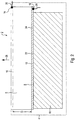
- the ultrasonic transducer 2 is a group radiator or group beam sensor trained and for this purpose has a number of individual Transducer elements 30, which are best shown in FIGS 4 can be seen where they are shown hatched. In 3 and 4, the ultrasonic transducer 2 is only partially without Housing 4 and damping body 10 shown.
- the geometric distribution of the individual converter elements 30 is according to FIG 3 only by the conductor tracks 24 of the conductor track film 8, so determined by the conductor pattern.
- each transducer element 30, for example the transducer element 30A a conductor track 24, for example the conductor track 24A.
- the converter element 30A Via the conductor track 24A, which acts as a contact electrode 22, the converter element 30A can be selective and controlled independently of the other converter elements 30 become.
- the transducer element 30A is due to the interaction of the conductor track 24A with the piezoceramic 6, since the Conductor 24A the geometric dimension of the transducer element 30A determined.
- the piezoceramic 6 becomes selective, that is, only in a certain one Area excited and vibrating in that area which one forms the hatched transducer element 30A. Due to the selective excitation there is a certain acoustic decoupling achieved to adjacent transducer elements 30.
- the ultrasonic transducer 2 according to FIG. 4 is therefore clear in its manufacture more expensive than that according to FIG 3. The latter is available So especially for uses where the quality the price of the ultrasonic transducer plays a subordinate role is decisive.
- the embodiment according to FIG. 4 has a decisive advantage on. Namely, it is a very simple one via the conductor tracks 24 Contacting the control lines 26 allows. With the conventional In contrast, ultrasonic transducers are contacting the control lines 26 directly on the evaporated Electrode, not least because of the fine geometric Structures, very heavy. To the high test frequencies to be able to fully exploit the achievable spatial resolution the individual transducer elements 30 preferably have a width B. which, in the case of test frequencies above 10 MHz 0.3 mm and below.
- a contact point 18 is located at the end of each conductor track 24 provided for connecting a control line 26.
- the conductor tracks 24 represent those for the determination of the transducer elements 30 essential geometric structure of the conductor track film 8 They are also preferred over their entire length as connection electrodes 21 trained and thus define in the embodiment 5 elongated transducer elements 30.
- Conductor tracks 24 form a so-called linear ultrasound transducer array.
- Such an array it is possible to pass through phase-delayed control of the individual converter elements 30 Ultrasonic signals in different signal or switch-off directions 28 to deliver. If the phase relationships are changed, so can the signal direction of the emitted ultrasound signal (and equally a received reflection signal) can be varied.
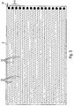
- the conductor track geometry has the conductor track film 8 according to FIG. 6 on.
- this is the geometric structure of the transducer elements 30 determining conductor track patterns by conductor track sections formed in the form of conductor track pads 36. This are designed in matrix form on the conductor track film 8. in the 6 form a 3x3 matrix.
- Each the conductor track pads 36 are connected via a connecting line 38 of the respective conductor track 24 is connected to a contact point 18. All contact points 18 of the individual conductor pads 36 are arranged in a contact area 40 of the conductor track film 8.
- the conductor track pads 36 form the electrodes 22 and are in either in direct electrical contact with the piezoceramic 6 (see FIG. 2) or are of this by a thin, which only slightly influences the capacitive coupling Layer, for example one for laminating the conductor track film 8 adhesive layer applied to the piezoceramic 6, electrically isolated.
Landscapes
- Engineering & Computer Science (AREA)
- Mechanical Engineering (AREA)
- Transducers For Ultrasonic Waves (AREA)
- Ultra Sonic Daignosis Equipment (AREA)
Abstract
Description
- FIG 1
- einen Querschnitt durch einen Ultraschallwandler längs der Leiterbahnen einer auf einer Piezokeramik aufge- brachten Leiterbahnfolie,
- FIG 2
- einen Querschnitt längs der Leiterbahnen durch eine al- ternative Ausgestaltung eines Ultraschallwandlers,
- FIG 3
- einen Querschnitt senkrecht zu den Leiterbahnen durch einen Ultraschallwandler
- FIG 4
- eine Querschnitt senkrecht zu den Leiterbahnen durch ei- ne alternative Ausbildung des Ultraschallwandlers,
- FIG 5
- eine Aufsicht auf eine Leiterbahnfolie, und
- FIG 6
- eine Aufsicht auf eine alternative Leiterbahnfolie.
Claims (10)
- Ultraschallwandler (2) mit einem piezoelektrischen Körper (6), der eine Anzahl von Wandlerelementen (30) aufweist,
dadurch gekennzeichnet, dass der piezoelektrische Körper (6) auf einer seiner Flachseiten (12) mit einer Leiterbahnfolie (8) versehen ist, deren Leiterbahnmuster (24,36) im Wesentlichen die geometrische Verteilung der Wandlerelemente (30) bestimmt. - Ultraschallwandler (2) nach Anspruch 1,
dadurch gekennzeichnet, dass der piezoelektrische Körper (6) eine einfache geometrische Form ohne spezielle Strukturierung aufweist. - Ultraschallwandler (2) nach Anspruch 1 oder 2,
dadurch gekennzeichnet, dass die Leiterbahnfolie (8) auf den piezoelektrische Körper (6) aufgeklebt oder durch mechanische Anpressung mit ihm verbunden ist. - Ultraschallwandler (2) nach einem der vorhergehenden Ansprüche,
dadurch gekennzeichnet, dass zum Ansteuern der einzelnen Wandlerelemente (30) Steuerleitungen (26) vorgesehen sind, die an der Leiterbahnfolie (8) kontaktiert sind. - Ultraschallwandler (2) nach einem der vorhergehenden Ansprüche,
dadurch gekennzeichnet, dass auf der der Leiterbahnfolie (8) abgewandten Rückseite (14) des piezoelektrischen Körpers (6) eine einzige Masseelektrode (16) vorgesehen ist. - Ultraschallwandler (2) nach einem der vorhergehenden Ansprüche,
dadurch gekennzeichnet, dass die Leiterbahnfolie (8) zwischen einem Dämpfungskörper (10) und dem piezoelektrischen Körper (6) angeordnet ist. - Ultraschallwandler (2) nach einem der vorhergehenden Ansprüche,
dadurch gekennzeichnet, dass der piezoelektrische Körper (6) gekrümmt ausgebildet ist. - Ultraschallwandler (2)nach einem der vorhergehenden Ansprüche,
dadurch gekennzeichnet, dass die piezoelektrische Komponente (6) zwischen den einzelnen Wandlerelementen (30) Einschnitte (32) aufweist. - Verfahren zur Herstellung eines Ultraschallwandlers (2) mit einer Anzahl von Wandlerelementen (30),
dadurch gekennzeichnet, dass auf einen piezoelektrischen Körper (6) eine Leiterbahnfolie (8) mit einem Leiterbahnmuster (24,26) aufgebracht wird, und dass das Leiterbahnmuster (24,26) im Wesentlichen die geometrische Verteilung der einzelnen Wandlerelemente (30) bestimmt. - Verfahren nach Anspruch 9,
dadurch gekennzeichnet, dass zum Ansteuern der einzelnen Wandlerelemente (30) vorgesehene Steuerleitungen (26) an der Leiterbahnfolie (8) kontaktiert werden.
Applications Claiming Priority (2)
| Application Number | Priority Date | Filing Date | Title |
|---|---|---|---|
| DE10018355 | 2000-04-13 | ||
| DE2000118355 DE10018355A1 (de) | 2000-04-13 | 2000-04-13 | Ultraschallwandler und Verfahren zur Herstellung eines Ultraschallwandlers |
Publications (3)
| Publication Number | Publication Date |
|---|---|
| EP1145772A2 true EP1145772A2 (de) | 2001-10-17 |
| EP1145772A3 EP1145772A3 (de) | 2003-09-03 |
| EP1145772B1 EP1145772B1 (de) | 2008-12-10 |
Family
ID=7638623
Family Applications (1)
| Application Number | Title | Priority Date | Filing Date |
|---|---|---|---|
| EP20010108898 Revoked EP1145772B1 (de) | 2000-04-13 | 2001-04-10 | Ultraschallwandler und Verfahren zur Herstellung eines Ultraschallwandlers |
Country Status (2)
| Country | Link |
|---|---|
| EP (1) | EP1145772B1 (de) |
| DE (2) | DE10018355A1 (de) |
Cited By (5)
| Publication number | Priority date | Publication date | Assignee | Title |
|---|---|---|---|---|
| WO2005107962A1 (de) * | 2004-05-08 | 2005-11-17 | Forschungzentrum Karlsruhe Gmbh | Ultraschallwandler sowie verfahren zur herstellung desselben |
| CN101733244A (zh) * | 2010-02-23 | 2010-06-16 | 邱咏 | 超声波换能器振子 |
| WO2012116952A1 (de) * | 2011-03-03 | 2012-09-07 | Intelligendt Systems & Services Gmbh | Prüfkopf zum prüfen eines werkstückes mit einer eine mehrzahl von wandlerelementen enthaltenden ultraschallwandleranordnung und verfahren zum herstellen eines solchen prüfkopfes |
| EP2631015A3 (de) * | 2012-02-24 | 2016-08-24 | Fraunhofer-Gesellschaft zur Förderung der angewandten Forschung e.V. | Ultraschallwandler zur Anregung und/oder zur Detektion von Ultraschall unterschiedlicher Frequenzen |
| GB2588218A (en) * | 2019-10-17 | 2021-04-21 | Darkvision Tech Inc | Acoustic transducer and method of manufacturing |
Families Citing this family (4)
| Publication number | Priority date | Publication date | Assignee | Title |
|---|---|---|---|---|
| DE102006038597B4 (de) * | 2006-08-17 | 2015-05-28 | Continental Automotive Gmbh | Schallwandler und Verfahren zu dessen Herstellung |
| DE102008011399A1 (de) | 2008-02-27 | 2009-09-03 | Hella Kgaa Hueck & Co. | Ultraschallwandler mit einem piezoelektrischen Element |
| US9404896B2 (en) * | 2012-11-19 | 2016-08-02 | General Electric Company | Two-dimensional TR probe array |
| DE102018103258B4 (de) * | 2018-02-14 | 2020-01-23 | Framatome Gmbh | Ultraschallprüfvorrichtung und Verfahren zur Herstellung eines Ultraschallprüfkopfs für eine derartige Ultraschallprüfvorrichtung |
Family Cites Families (11)
| Publication number | Priority date | Publication date | Assignee | Title |
|---|---|---|---|---|
| US4117074A (en) * | 1976-08-30 | 1978-09-26 | Tiersten Harry F | Monolithic mosaic piezoelectric transducer utilizing trapped energy modes |
| JPS57169671A (en) * | 1981-04-10 | 1982-10-19 | Nippon Dempa Kogyo Co Ltd | Ultrasonic probe |
| DE3149732A1 (de) * | 1981-12-15 | 1983-07-21 | Siemens AG, 1000 Berlin und 8000 München | Ultraschallwandleranordnung |
| JPH0660896B2 (ja) * | 1984-11-02 | 1994-08-10 | 株式会社日立製作所 | 超音波探触子 |
| DE3611669A1 (de) * | 1985-04-10 | 1986-10-16 | Hitachi Medical Corp., Tokio/Tokyo | Ultraschallwandler |
| US4670683A (en) * | 1985-08-20 | 1987-06-02 | North American Philips Corporation | Electronically adjustable mechanical lens for ultrasonic linear array and phased array imaging |
| JPH02234600A (ja) * | 1989-03-07 | 1990-09-17 | Mitsubishi Mining & Cement Co Ltd | 圧電変換素子 |
| JP2745147B2 (ja) * | 1989-03-27 | 1998-04-28 | 三菱マテリアル 株式会社 | 圧電変換素子 |
| US5291090A (en) * | 1992-12-17 | 1994-03-01 | Hewlett-Packard Company | Curvilinear interleaved longitudinal-mode ultrasound transducers |
| US5541468A (en) * | 1994-11-21 | 1996-07-30 | General Electric Company | Monolithic transducer array case and method for its manufacture |
| EP0796669A3 (de) * | 1996-03-19 | 1998-04-29 | Siemens Aktiengesellschaft | Ultraschallwandler |
-
2000
- 2000-04-13 DE DE2000118355 patent/DE10018355A1/de not_active Withdrawn
-
2001
- 2001-04-10 EP EP20010108898 patent/EP1145772B1/de not_active Revoked
- 2001-04-10 DE DE50114555T patent/DE50114555D1/de not_active Expired - Lifetime
Cited By (14)
| Publication number | Priority date | Publication date | Assignee | Title |
|---|---|---|---|---|
| WO2005107962A1 (de) * | 2004-05-08 | 2005-11-17 | Forschungzentrum Karlsruhe Gmbh | Ultraschallwandler sowie verfahren zur herstellung desselben |
| DE102004022838A1 (de) * | 2004-05-08 | 2005-12-01 | Forschungszentrum Karlsruhe Gmbh | Ultraschallwandler sowie Verfahren zur Herstellung desselben |
| US7471034B2 (en) | 2004-05-08 | 2008-12-30 | Forschungszentrum Karlsruhe Gmbh | Ultrasound transducer and method of producing the same |
| CN101733244A (zh) * | 2010-02-23 | 2010-06-16 | 邱咏 | 超声波换能器振子 |
| WO2012116952A1 (de) * | 2011-03-03 | 2012-09-07 | Intelligendt Systems & Services Gmbh | Prüfkopf zum prüfen eines werkstückes mit einer eine mehrzahl von wandlerelementen enthaltenden ultraschallwandleranordnung und verfahren zum herstellen eines solchen prüfkopfes |
| US9423382B2 (en) | 2011-03-03 | 2016-08-23 | Areva Gmbh | Test head for testing a workpiece having an ultrasonic transducer configuration containing a plurality of ultrasonic transducers and process for producing such a test head |
| EP2631015A3 (de) * | 2012-02-24 | 2016-08-24 | Fraunhofer-Gesellschaft zur Förderung der angewandten Forschung e.V. | Ultraschallwandler zur Anregung und/oder zur Detektion von Ultraschall unterschiedlicher Frequenzen |
| GB2588218A (en) * | 2019-10-17 | 2021-04-21 | Darkvision Tech Inc | Acoustic transducer and method of manufacturing |
| GB2588218B (en) * | 2019-10-17 | 2021-10-27 | Darkvision Tech Ltd | Acoustic transducer and method of manufacturing |
| CN114502927A (zh) * | 2019-10-17 | 2022-05-13 | 暗视技术公司 | 声换能器和制造方法 |
| EP4045880A1 (de) | 2019-10-17 | 2022-08-24 | Darkvision Technologies Inc. | Schallwandler und verfahren zur herstellung |
| EP4045880A4 (de) * | 2019-10-17 | 2023-11-01 | Darkvision Technologies Inc. | Schallwandler und verfahren zur herstellung |
| CN114502927B (zh) * | 2019-10-17 | 2025-04-29 | 暗视技术公司 | 声换能器和制造方法 |
| US12569884B2 (en) | 2019-10-17 | 2026-03-10 | Darkvision Technologies Inc | Acoustic transducer and method of manufacturing |
Also Published As
| Publication number | Publication date |
|---|---|
| EP1145772A3 (de) | 2003-09-03 |
| EP1145772B1 (de) | 2008-12-10 |
| DE10018355A1 (de) | 2001-12-20 |
| DE50114555D1 (de) | 2009-01-22 |
Similar Documents
| Publication | Publication Date | Title |
|---|---|---|
| DE4010294C2 (de) | ||
| DE3525724C2 (de) | ||
| DE69710314T2 (de) | Schallwandler mit mehreren elementen und gemeinsamer massenelektrode | |
| EP0025092B1 (de) | Ultraschallwandleranordnung und Verfahren zu ihrer Herstellung | |
| DE102009000379B4 (de) | Ultraschalltransducer für einen Näherungssensor | |
| DE102004054293A1 (de) | Verfahren zur Herstellung eines mehrschichtigen keramischen akustischen Wandlers | |
| DE112007002645T5 (de) | Ultraschallsonde | |
| DE3021449A1 (de) | Ultraschallwandleranordnung und verfahren zu seiner herstellung | |
| DE1913979A1 (de) | Flachlautsprecher mit piezoelektrischen Antriebselementen | |
| EP1145772A2 (de) | Ultraschallwandler und Verfahren zur Herstellung eines Ultraschallwandlers | |
| DE4435914C2 (de) | Piezoelektrischer Antrieb für einen Tintenstrahlaufzeichnungskopf und Verfahren zu dessen Herstellung | |
| DE102013107154A1 (de) | Antriebsvorrichtung | |
| DE69832570T2 (de) | Piezoelektrischer Resonator und elektronisches Bauelement damit | |
| EP0924957B1 (de) | Anschlusskontaktierung | |
| WO2018141544A1 (de) | Planardynamischer wandler | |
| EP0166180A1 (de) | Hydrophon | |
| EP4291338B1 (de) | Vorrichtung und verfahren zur herstellung einer vorrichtung | |
| DE2838288C3 (de) | Piezoelektrischer Schwinger | |
| DE102013222076A1 (de) | Schallwandler und Herstellungsverfahren für einen Schallwandler | |
| EP0040374A1 (de) | Ultraschallwandleranordnung und Verfahren zu seiner Herstellung | |
| DE3019410A1 (de) | Verfahren zum herstellen einer ultraschallwandleranordnung | |
| DE3784078T2 (de) | Echographie-wandler mit verbindungsschaltung. | |
| DE19704389C2 (de) | Aktor aus Einzelelementen | |
| DE69524817T2 (de) | Diagnoseultraschallwandleranordnung mit Elevationsfokus | |
| DE69936836T2 (de) | Piezoelektrischer transformator |
Legal Events
| Date | Code | Title | Description |
|---|---|---|---|
| PUAI | Public reference made under article 153(3) epc to a published international application that has entered the european phase |
Free format text: ORIGINAL CODE: 0009012 |
|
| AK | Designated contracting states |
Kind code of ref document: A2 Designated state(s): AT BE CH CY DE DK ES FI FR GB GR IE IT LI LU MC NL PT SE TR |
|
| AX | Request for extension of the european patent |
Free format text: AL;LT;LV;MK;RO;SI |
|
| PUAL | Search report despatched |
Free format text: ORIGINAL CODE: 0009013 |
|
| AK | Designated contracting states |
Kind code of ref document: A3 Designated state(s): AT BE CH CY DE DK ES FI FR GB GR IE IT LI LU MC NL PT SE TR |
|
| AX | Request for extension of the european patent |
Extension state: AL LT LV MK RO SI |
|
| 17P | Request for examination filed |
Effective date: 20040207 |
|
| AKX | Designation fees paid |
Designated state(s): DE ES FR GB NL |
|
| GRAP | Despatch of communication of intention to grant a patent |
Free format text: ORIGINAL CODE: EPIDOSNIGR1 |
|
| GRAS | Grant fee paid |
Free format text: ORIGINAL CODE: EPIDOSNIGR3 |
|
| GRAA | (expected) grant |
Free format text: ORIGINAL CODE: 0009210 |
|
| AK | Designated contracting states |
Kind code of ref document: B1 Designated state(s): DE ES FR GB NL |
|
| REG | Reference to a national code |
Ref country code: GB Ref legal event code: FG4D Free format text: NOT ENGLISH |
|
| REF | Corresponds to: |
Ref document number: 50114555 Country of ref document: DE Date of ref document: 20090122 Kind code of ref document: P |
|
| RAP2 | Party data changed (patent owner data changed or rights of a patent transferred) |
Owner name: INTELLIGENDT SYSTEMS & SERVICES GMBH |
|
| PG25 | Lapsed in a contracting state [announced via postgrant information from national office to epo] |
Ref country code: ES Free format text: LAPSE BECAUSE OF FAILURE TO SUBMIT A TRANSLATION OF THE DESCRIPTION OR TO PAY THE FEE WITHIN THE PRESCRIBED TIME-LIMIT Effective date: 20090321 |
|
| NLT2 | Nl: modifications (of names), taken from the european patent patent bulletin |
Owner name: INTELLIGENDT SYSTEMS & SERVICES GMBH Effective date: 20090701 |
|
| PLBI | Opposition filed |
Free format text: ORIGINAL CODE: 0009260 |
|
| 26 | Opposition filed |
Opponent name: L-3 COMMUNICATIONS ELAC NAUTIK GMBH Effective date: 20090908 |
|
| PLAX | Notice of opposition and request to file observation + time limit sent |
Free format text: ORIGINAL CODE: EPIDOSNOBS2 |
|
| NLT1 | Nl: modifications of names registered in virtue of documents presented to the patent office pursuant to art. 16 a, paragraph 1 |
Owner name: INTELLIGENDT SYSTEMS & SERVICES GMBH |
|
| NLR1 | Nl: opposition has been filed with the epo |
Opponent name: L-3 COMMUNICATIONS ELAC NAUTIK GMBH |
|
| REG | Reference to a national code |
Ref country code: FR Ref legal event code: CD Ref country code: FR Ref legal event code: TP |
|
| PLBB | Reply of patent proprietor to notice(s) of opposition received |
Free format text: ORIGINAL CODE: EPIDOSNOBS3 |
|
| REG | Reference to a national code |
Ref country code: GB Ref legal event code: 732E Free format text: REGISTERED BETWEEN 20100325 AND 20100331 |
|
| PGFP | Annual fee paid to national office [announced via postgrant information from national office to epo] |
Ref country code: FR Payment date: 20110427 Year of fee payment: 11 |
|
| PGFP | Annual fee paid to national office [announced via postgrant information from national office to epo] |
Ref country code: NL Payment date: 20110420 Year of fee payment: 11 Ref country code: GB Payment date: 20110419 Year of fee payment: 11 |
|
| PGFP | Annual fee paid to national office [announced via postgrant information from national office to epo] |
Ref country code: DE Payment date: 20110620 Year of fee payment: 11 |
|
| PLAB | Opposition data, opponent's data or that of the opponent's representative modified |
Free format text: ORIGINAL CODE: 0009299OPPO |
|
| R26 | Opposition filed (corrected) |
Opponent name: L-3 COMMUNICATIONS ELAC NAUTIK GMBH Effective date: 20090908 |
|
| RDAF | Communication despatched that patent is revoked |
Free format text: ORIGINAL CODE: EPIDOSNREV1 |
|
| REG | Reference to a national code |
Ref country code: NL Ref legal event code: V1 Effective date: 20121101 |
|
| GBPC | Gb: european patent ceased through non-payment of renewal fee |
Effective date: 20120410 |
|
| RDAG | Patent revoked |
Free format text: ORIGINAL CODE: 0009271 |
|
| STAA | Information on the status of an ep patent application or granted ep patent |
Free format text: STATUS: PATENT REVOKED |
|
| REG | Reference to a national code |
Ref country code: FR Ref legal event code: ST Effective date: 20121228 |
|
| PG25 | Lapsed in a contracting state [announced via postgrant information from national office to epo] |
Ref country code: GB Free format text: LAPSE BECAUSE OF NON-PAYMENT OF DUE FEES Effective date: 20120410 |
|
| 27W | Patent revoked |
Effective date: 20120924 |
|
| REG | Reference to a national code |
Ref country code: DE Ref legal event code: R119 Ref document number: 50114555 Country of ref document: DE Effective date: 20121101 |
|
| PG25 | Lapsed in a contracting state [announced via postgrant information from national office to epo] |
Ref country code: FR Free format text: LAPSE BECAUSE OF NON-PAYMENT OF DUE FEES Effective date: 20120430 |