EP1145773A2 - Siebkasten für Pulverteilchensieb - Google Patents
Siebkasten für Pulverteilchensieb Download PDFInfo
- Publication number
- EP1145773A2 EP1145773A2 EP01115065A EP01115065A EP1145773A2 EP 1145773 A2 EP1145773 A2 EP 1145773A2 EP 01115065 A EP01115065 A EP 01115065A EP 01115065 A EP01115065 A EP 01115065A EP 1145773 A2 EP1145773 A2 EP 1145773A2
- Authority
- EP
- European Patent Office
- Prior art keywords
- frame
- sifter
- fine powder
- powder
- rough
- Prior art date
- Legal status (The legal status is an assumption and is not a legal conclusion. Google has not performed a legal analysis and makes no representation as to the accuracy of the status listed.)
- Withdrawn
Links
Images


Classifications
-
- B—PERFORMING OPERATIONS; TRANSPORTING
- B07—SEPARATING SOLIDS FROM SOLIDS; SORTING
- B07B—SEPARATING SOLIDS FROM SOLIDS BY SIEVING, SCREENING, SIFTING OR BY USING GAS CURRENTS; SEPARATING BY OTHER DRY METHODS APPLICABLE TO BULK MATERIAL, e.g. LOOSE ARTICLES FIT TO BE HANDLED LIKE BULK MATERIAL
- B07B1/00—Sieving, screening, sifting, or sorting solid materials using networks, gratings, grids, or the like
- B07B1/46—Constructional details of screens in general; Cleaning or heating of screens
- B07B1/4609—Constructional details of screens in general; Cleaning or heating of screens constructional details of screening surfaces or meshes
- B07B1/4618—Manufacturing of screening surfaces
-
- B—PERFORMING OPERATIONS; TRANSPORTING
- B07—SEPARATING SOLIDS FROM SOLIDS; SORTING
- B07B—SEPARATING SOLIDS FROM SOLIDS BY SIEVING, SCREENING, SIFTING OR BY USING GAS CURRENTS; SEPARATING BY OTHER DRY METHODS APPLICABLE TO BULK MATERIAL, e.g. LOOSE ARTICLES FIT TO BE HANDLED LIKE BULK MATERIAL
- B07B1/00—Sieving, screening, sifting, or sorting solid materials using networks, gratings, grids, or the like
- B07B1/28—Moving screens not otherwise provided for, e.g. swinging, reciprocating, rocking, tilting or wobbling screens
- B07B1/38—Moving screens not otherwise provided for, e.g. swinging, reciprocating, rocking, tilting or wobbling screens oscillating in a circular arc in their own plane; Plansifters
-
- B—PERFORMING OPERATIONS; TRANSPORTING
- B07—SEPARATING SOLIDS FROM SOLIDS; SORTING
- B07B—SEPARATING SOLIDS FROM SOLIDS BY SIEVING, SCREENING, SIFTING OR BY USING GAS CURRENTS; SEPARATING BY OTHER DRY METHODS APPLICABLE TO BULK MATERIAL, e.g. LOOSE ARTICLES FIT TO BE HANDLED LIKE BULK MATERIAL
- B07B1/00—Sieving, screening, sifting, or sorting solid materials using networks, gratings, grids, or the like
- B07B1/46—Constructional details of screens in general; Cleaning or heating of screens
-
- B—PERFORMING OPERATIONS; TRANSPORTING
- B07—SEPARATING SOLIDS FROM SOLIDS; SORTING
- B07B—SEPARATING SOLIDS FROM SOLIDS BY SIEVING, SCREENING, SIFTING OR BY USING GAS CURRENTS; SEPARATING BY OTHER DRY METHODS APPLICABLE TO BULK MATERIAL, e.g. LOOSE ARTICLES FIT TO BE HANDLED LIKE BULK MATERIAL
- B07B2201/00—Details applicable to machines for screening using sieves or gratings
- B07B2201/02—Fastening means for fastening screens to their frames which do not stretch or sag the screening surfaces
Definitions
- the present invention relates to a sifter frame used as a sifter for separating the particle sizes of powder particles such as flour and the like, and more specifically, but not exclusively, to a structure of an intimate contact type sifter frame used by being stacked into multi-stages to sift and separate powder particles.
- Sifters are conventionally used to separate the particle sizes of powder particles such as flour and the like. The sifter will be described below with respect to the separation of the particle sizes of flour by way of example.
- Sifter types known as plan sifter, square sifter and the like are used in the flour milling industry from old times to separate the particle sizes of flour, and at present various types of sifters such as the modifications of the above sifters and intermediate type sifters (such as a junior type sifter and the like) are put into practical use. These sifters are fundamentally arranged such that powder having a small particle size in powder supplied onto the sifter is caused to pass through the sifter downwardly while a multiplicity of stacked sifter frames are caused to make a circular motion to separate the particle sizes of the supplied powder.
- a reason why the flour sifter is composed of the sifter frames stacked to the multi-stages as described above is to make the sifter area as large as possible, which is desirable to effectively separate flour by moving the flour on the surface of the sifter.
- the area of the sifter per unit area of installation is increased to save the installation area in such a manner that the sifter is composed to sifter frames stacked to the multi-stages and a sifter surface on which flour moves is formed so that the sifter surface vertically meanders in the sifter.
- the sifter is usually composed of a group of stacked square sifter frames tightened from the upper and lower sides thereof or a group of sifter frames which are stacked to ten to twenty stages and accommodated in a sifter frame box called a box so that they are horizontally tightened and fixed and also tightened and fixed from the upper side thereof. Then, the box and the like are driven by a drive unit composed of an eccentric shaft provided with a balance weight and a drive shaft to make a circular motion within a horizontal plane at high speed.
- sifter frame which has a structure for limiting a portion to be replaced only to a sifter net. That is, there are generally used a pair of a frame member of about 1m x 1m (referred to as an outer frame) and a frame member having a sifter net stretched therein as an object to be replaced (referred to as an inner frame) with the inner frame being engaged with the outer frame.
- the conventional type sifter frame shown in these figures has a combination type structure arranged such that a rectangular inner frame 500 (refer to FIG. 13) is fitted within the inner frame fitting portion of an outer frame 600 (refer to FIG. 14), the inner frame 500 having a sifter net 501 stretched over the upper surface thereof to separate flour to powder on a sifter (rough powder) and powder below the sifter (through: fine powder), and the outer frame 600 being in contact with the three circumferential sides of the inner frame and having a longitudinal path in an upward/downward direction (refer to FIG. 15).
- the above inner frame 500 shown in FIG. 13 is fitted within the inner frame fitting portion of an outer frame 600 (refer to FIG. 14)
- the inner frame 500 having a sifter net 501 stretched over the upper surface thereof to separate flour to powder on a sifter (rough powder) and powder below the sifter (through: fine powder)
- the outer frame 600 being in contact with the three circumferential sides of the inner frame and having
- FIG. 13 is composed of wood frame member 502 - 505 of, for example, wood for constituting a rectangular four-side frame and a sifter net 501 having a predetermined sifting mesh and stretched over reinforcing wood bars 506, 507 formed to a cross shape and disposed inwardly of the rectangular frame member.
- a crimp net having a rough mesh is usually stretched below the sifter net 501 in parallel therewith and a cleaner such as, for example, a triangular flat cleaner having a hemispheric projection is movably interposed between the upper and lower nets so that clogging of the sifter net 501 is prevented by causing the cleaner to beat the net when the sifter is in operation.
- the outer frame 600 shown in FIG. 14 is composed of an inner frame fitting portion within which the above inner frame 500 is fitted in contact with or biased to an outer side wall outer block member 610 as one of the four sides of the rectangular frame forming the outer block of the outer frame 600 and longitudinal paths 601, 602, 602 disposed outwardly of the inner frame fitting portion in an upward/downward direction along the inside of each of the remaining three sides except the side wall 610 of the above one side.
- the outer frame 600 is composed of a pair of parallel inner side walls (frame members) 607, 607 disposed to form the above inner frame fitting portion, three inner frame fitting stand frames 604, 605, 606 fixed over the lower surfaces of the inner side walls 607, 607.
- a pair of outer side walls 608, 608 is disposed separately to form the fine powder dropping ports 602, 602 to the outside of each of the above outer inside walls 607, 607, and the outer side wall 610 is disposed in contact with the outside of the inner frame fitting stand frame 606.
- An outer side wall 609 is separately disposed to form a rough powder dropping port 601 (usually, called an over port) outwardly of the inner frame fitting stand frame 604, and a receiving plate (fine powder flowing plate) 603 is provided as a bottom surface for introducing fine powder (through) having passed through the sifter net 501 of the inner frame to be fitted to the above right and left dropping ports 602, 602.
- the inner side walls 607, 607 are fixed to the outer side walls 608, 608 at suitable positions through intermediate brackets 613, 613, and the inner frame fitting stand frame 604 is fixed to the outer side wall 609 through an intermediate bracket 615 in the same way.
- Numeral 614 denotes blocks disposed at four corners to close the unnecessary space portions in the outer frame as well as to increase the strength of a fitting structure in an upward/downward direction.
- the receiving plate 603 is composed of a stainless steel sheet or the like fixed to the respective lower surfaces of the above inner frame fitting stand frames 604, 605, 606 by screws. With this arrangement, each of the right and left ends of the receiving plate 603 has a gap corresponding to the thickness of the stand frames 604, 605 between the lower surface of the inner side wall 607 and the receiving plate 603, and these gaps form slit-shaped fine powder dropping ports 617 for dropping fine powder dropped onto the receiving plate 603 into the right and left fine powder dropping ports 602. Note, the receiving plate 603 is disposed substantially at the intermediate position in the upward-downward direction of the sifter frame in a bottom-lifted-state (refer to FIG. 16).
- a direction in which a pair of the fine powder dropping ports 602 is separated from each other is referred to as a right/left direction and a direction orthogonal to the right/left direction in a horizontal direction is referred to as a forward/backward direction.
- a group of the sifter frames having the above arrangement can be constructed by stacking a multiplicity of the sifter frames in such a manner that the positions of the rough powder dropping ports 601 are successively reversed (alternately disposed) on the respective stages (refer to FIG. 16). Then, powder particles-having moved (flown) on the sifter net 501 of a certain stage drop into the rough powder dropping port 501 of the inner frame 5 along the inclined surface 502a of the frame member 502 in contact with the rough powder dropping port 601 and move onto the sifter net of the sifter frame of the next lower stage. Further, fine powder having passed through the sifter net 501 drops onto the receiving plate 603 and further drops into the fine powder dropping ports 602 through the right and left slit-shaped fine powder dropping port 617.
- press beams 620, 620 are disposed between the outer side walls 609, 610 below the receiving plate 603 of the outer frame 600 so that the press beams 620, 620 extend to the upper surfaces of the inner side wall 607 and the frame member 504 (or 505) of the inner frame of the lower stage sifter frame to cover them in contact therewith (refer to FIG. 16).
- the sifter is naturally required to securely prevent the mixture of rough powder with fine powder caused through the gap defined at the inner frame fitting position.
- the lower portion of the frame member 502 of the inner frame 500 is provided with a stepped portion as shown in FIG. 15 (b) and the stepped leg portion 502b is engaged with the stepped portion 604a of the inner frame fitting stand frame 604 formed in correspondence with the outer frame to form seal portions.
- FIG. 15(a) is an unfolded view for explaining the relationship between the outer frame 600 and the inner frame 500 fitted therewith
- FIG. 16 is an unfolded view for explaining a state that the sifter frames each arranged as described above are stacked with the rough powder dropping ports 601 thereof successively disposed alternately.
- surfaces 700, 701 shown cross-hatched serve as seal surfaces for strongly pressing the inner frame 500 of the lower stage sifter frame downwardly by the upper stage sifter frame (outer frame 600) so as to increase the seal pressure of the above seal portions and at the same time to seal and partition a region (rough powder region) where rough powder flows from a region where fine powder flows (fine powder region).
- a suitable seal sheet is applied to the surfaces 700, 701 as necessary.
- the inventors have found the following fact by examining a cause of the mixture of rough powder with fine powder, taking the present state mentioned above into consideration. That is, there is a problem that although the mixture of rough powder with fine powder in the conventional sifter frame is not caused on the above seal surfaces 700, 701 which are in intimate contact with each other under pressure, the mixture of them is caused at the portion where the frame member 502 is fitted with the inner frame fitting stand frame 604.
- brackets 616 provided to form the inner frame fitting portion of the outer frame are engaged with the extreme (front) end surfaces (surfaces facing to the rough powder dropping port) 504a, 505a of the right and left frame members 504, 505 of the inner frame to seal a fine powder region and a rough powder region, no pressure is applied to make the intimate contact of the both surfaces of the fitting portion in the structure. More specifically, the direction of a horizontal force for causing the both surfaces to come into intimate contact with each other is different 90° from a vertical force for causing the upper and lower sifter frames to come into intimate contact with each other.
- the rough powder having entered the above gap further moves and enters the fine powder region as shown by dotted lines 802, 803, by which the aforesaid mixture is caused.
- Preferred embodiments of the present invention provide a novel powder separating sifter frame, alleviating the above various problems, and capable of reducing the storing volume by limiting the portion of the sifter frame to be prepared and stored, as well as satisfying a requirement for saving labour needed by a replacement job, and securely preventing the mixing of rough powder with fine powder, which has been sometimes caused by a conventional sifter frame.
- a sifter frame for a powder particle sifter comprising:
- an air-tight seal sheet is applied to at least one of said arc-shaped or inclined engaging surfaces where the projecting horn portions of the outer block frame members of said inner frame are engaged with said receiving portions formed on said outer frame on which said projecting horn portions are to be placed.
- the side surface of said inner frame adjacent said rough powder dropping port is formed to be flush with the side surface of said partition wall facing said rough powder dropping port, and a shield sheet member for covering up at least part of the side surface of said outer frame is provided on the side surface of said inner frame.
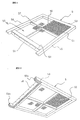
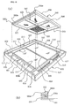
- numeral 5 in FIG. 1 and FIG. 2 denotes an inner frame composed of a substantially rectangular four-side frame formed from outer block frame members 52, 53, 54, 55 each composed of, in the embodiment, a wood square column member, and sifter net region 50 is formed in the inner frame 5.
- Reinforcing wood bars 56, 57 formed to a cross shape are disposed between the frame members 52 and 53 and the frame members 54 and 55 respectively, and a sifter net 51 is stretched over the top surfaces of the frame members 52, 53, 54, 55 and the reinforcing wood bars 56, 57.
- the frame members 52 - 55 are arranged such that the upper surfaces thereof are flush with the lower surfaces thereof as well as the frame member 52 is composed of a square column member having a larger cross sectional area so that the frame member 52 has a modulus of section larger than those of the other three frame members 53 - 55.
- a reason why the upper surfaces of the inner frame is formed to have the same level is to make surfaces, which are to be sealed when sifter frames are stacked to multi-stages, flat.
- a reason why the frame member 52 is composed of the square column member having a cross sectional area larger than those of the other three frame members is that a maximum bending rigidity is required for the frame member 52.
- One of the features of the inner frame 5 of this embodiment is that when the inner frame 5 is fitted within an outer frame to be described later, a thin flat metal bar 58 is fixed to the front side surface of the frame member 52 which is to be in contact with a rough powder dropping port (69 to be described later) by means of screws or the like and further that the lower end of the flat bar 58 projects downwardly of the lower surface of the frame member 52 by a predetermined distance (refer to FIGS. 1, 2).
- the flat metal bar 58 is mounted on the front side surface of the frame member 52 in the embodiment to securely prevent the invasion of rough powder into fine powder through engaging surfaces where the frame member 52 of the inner frame engages the receiving stand (68 to be described later) of the outer frame. This is provided to position the frame member 52 thereon in such a manner that the meeting line of the above engaging surfaces facing the rough powder dropping port is covered with the flat metal bar 58 as described above.
- a packing may be interposed between the flat bar 58 and the frame member 52.
- the embodiment employs a characteristic arrangement that the extreme (front) ends of the right and left frame members 54, 55, which are to be in contact with fine powder dropping ports (65 to be described later) when the inner frame 5 is fitted within the outer frame to be described later, project towards the rough powder dropping port side, beyond position of the frame member 52, and the lower corner portions of the extreme (front) ends of the right and left frame members 54, 55 have convex arc-shaped surfaces 54a, 55a.
- elastic seal packing members 88 each having a predetermined uniform thickness are applied to the convex arc-shaped surfaces 54a, 55a and the lower surface of the frame member 52 shown by cross-hatching.
- the above arrangement is employed in the embodiment to form seal surfaces on which a compression force (depressing force) acts in a generally vertical direction while enabling the easy and smooth mounting and dismounting of the inner frame on and from the outer frame in such a manner that the lower corner portions at the extreme ends of the frame members 54, 55 are formed to the convex arc-shaped surfaces 54a, 55a engaged with the concave arc-shaped surfaces 82a, 82a of the outer frame corresponding thereto in order to that the invasion of rough powder into a fine powder region from the rough powder dropping port is securely prevented.
- the elastic seal packing members are applied to further improve the sealing property of the engaging surfaces.
- the sifter frame of the embodiment is similar to the conventional sifter frame except the above characteristic arrangement, and, for example, a crimp net may be stretched in the vicinity of the lower side of the sifter net 51 in parallel therewith with a cleaner (neither shown) movably interposed between the nets to prevent the clogging of the net.
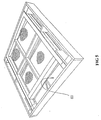
- FIG 3 and FIG. 4 show the outer frame 6 constituting the sifter frame of the embodiment.
- the outer frame 6 is a rectangular four-sided frame, formed by outer side walls (outer block members) 62, 63, 64, 64 each composed of a wood sheet.
- a pair of inner side walls 61, 61 each composed of a flat metal bar are disposed between the outer side walls 62, 63 spaced apart from the outer side walls 64, 64 in parallel therewith so that the fine powder dropping ports 65, 65 are defined to the inside of a pair of the confronting outer side walls 64, 64 of the above outer side walls 62, 63, 64, 64, and further a pair of receiving stands (inner frame extreme end projection receiving stands) 82, 82 each composed of a resin member are disposed at the both ends (inside surfaces of the inner side walls 61, 61) of the rough powder dropping port 69 formed to the inside of the outer side wall 62.
- the receiving stands 82, 82 are provided with the concave arc-shaped surfaces 82a, 82a to and with which the convex arc-shaped surfaces 54a, 55a of the lower corner portions of the extreme ends of the frame members 54, 55 of the aforesaid inner frame 5 correspond and are engaged.
- a recessed portion 60 into and with which the above inner frame 5 is inserted and fitted substantially in close contact therewith is formed by the outer side wall 63, a pair of the inner side walls 61, 61 and a pair of the receiving stands 82, 82.
- numeral 68 denotes a partition wall for partitioning a fine powder receiving region provided with a receiving plate 67 from the rough powder dropping port 69 defined to the inside of the outer side wall 62 and the partition wall 68 also serves as a receiving plate on which the frame member 52 of the inner frame is to be place.
- the rough powder dropping port 69 is formed as a space region surrounded by the partition wall 68, a pair of the receiving stands 82 and the outer side wall 62 in parallel with the partition wall 68 and passing through in a generally vertical direction.
- the fine powder receiving region is formed in such a manner that inner frame receiving stands 73, 74 each composed of a wood bar as high as the partition wall 68 are disposed between a pair of the inner side walls 61, 61 on the lower surfaces thereof, and a rectangular stainless steel receiving plate 67 is attached and fixed to the lower surfaces of the inner frame receiving stands 73, 74 by wood screws.
- the receiving plate 67 is high at the central portion thereof in a right/left direction (direction in which the fine powder dropping ports 65, 65 are spaced apart from each other) and forms gently descending inclinations toward the right and left directions (toward the fine powder dropping ports 65), whereby fine powder having passed through the sifter net 51 promptly drops into the fine powder dropping ports 65.
- Lower inner side walls 76, 76 constituting a pair in a vertical direction with the inner side walls 61, 61 are disposed under both the right and left ends of the receiving plate 67 and the lower surfaces of the lower inner side walls 76, 76 are flush with the lower surfaces of the outer side walls 62, 63, 64 and extend over and cover the upper surfaces of the inner side wall 61 of the outer frame of a sifter frame stacked to the lower stage and the inner frame member 54 (or 55).
- the inner frame receiving stand 74 is disposed in contact with the outer side wall 63 and the other inner frame receiving stand 73 is disposed at an intermediate position between the partition wall 68 and the inner frame receiving stand 74.
- the receiving plate 67 provides a space for the fine powder region for receiving fine powder (through) having passed through the sifter net 51 of the inner frame 5 inserted into and fitted within the inner frame fitting portion.
- the fine powder is dropped into the fine powder dropping ports 65 from slit-shaped fine powder dropping ports 75 each defined between the lower surface of the inner side wall 61 and the receiving plate 67.
- the upper surface of the partition wall also serves as the inner frame receiving stand 68 and the upper surfaces of the inner frame receiving stands 73, 74 in the inner frame fitting portion 60 are located at such a depth that when the inner frame 5 is placed on the above surfaces by being inserted into and fitted within the inner frame fitting portion 60, the upper surfaces of the inner side wall 61 and the outer side walls 62, 63, 64 are flush with the upper surface of the inner frame 5.
- the partition wall which serves as the inner frame receiving stand 68 has a predetermined width of a stepped and lowered portion at its upper corner on the rough powder dropping port 69 side.
- the seal packing member 88 applied to the front half portion of the lower surface of the frame member 52 continuously to the convex arc-shaped surface 54a (55a) at the extreme end of the frame member 54 (55) of the inner frame 5 is engaged with the stepped lower portion 68a so that a seal property is more effectively exhibited by the seal packing member 88.
- a central portion reinforcing member 86 is disposed between the outer side wall 62 and the outer side wall 63 at the centre of the lower surface of the receiving plate 67 to support the receiving plate 67 from the lower surface thereof. Note, both ends of the central portion reinforcing member 86 are fixed to the outer side walls 62, 63 and a bracket 66 is also fixed on the reinforcing member 86. Although the central portion reinforcing member 86 is used to increase the structural strength of the outer frame, since the lower side region of the receiving plate 67 is a region where rough powder moves (transfers) on the sifter net, there is a problem that it is not desirable to attach a member having a high dimension to this area.
- the member 86 since the member 86 is used for reinforcement, it is desired that the member 86 has a sufficient strength and rigidity against a bending moment. To satisfy these two requirements, it is desirable in many cases to use a reinforcing member of metal which has a strength and rigidity larger than those of a wood member even if its cross sectional area is smaller than that of the wood member.
- the strength of the overall structure is improved in such a manner that blocks 71, 71, 81, 81 are fixed at the four corners (both ends of the fine powder dropping ports 65) of the frame constituting the rectangular four-side outer block and reinforcing intermediate brackets 72, 72 are fixed between the outer side walls 62, 63 and the inner side walls 61, 61.
- Numerals 83, 83 denote partition wall brackets fixed to close the gaps between the inner side walls 61 and the lower inner side walls 76 at the both ends of the rough powder dropping port 69.
- Another feature of the outer frame 6 of the embodiment is the provision of a lower stage inner frame pressing projection 87. That is, the lower stage inner frame pressing projection 87 is disposed below the central portion reinforcing member 86 in such a manner that an end of the projection 87 is fixed to the outer side wall 63 and the lower surface thereof is flush with the lower surfaces of the side walls 62, 63, 64. With this arrangement, the central portion of the frame member 52 of the inner frame of a sifter frame stacked to the lower stage is depressed downwardly.
- the length of the lower stage inner frame pressing projection 87 is set to such a length that the extended end of the projection reaches the upper surface of the frame member 52 of the inner frame of the lower stage but does not reach the sifter net 51 thereof.
- the central portion of the frame member 52 of the inner frame of the sifter frame stacked to the lower stage receives a vertically downward depressing force, so that a sealing force, which is produced on the engaged seal surfaces between the frame member 52 of the inner frame and the partition wall also serving as the receiving stand 68 of the outer frame to be fitted with each other, can be obtained at the central portions of these members and thus a sufficient seal effect can be secured.
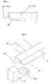
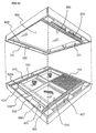
- FIG. 5 shows a state assembly of a sifter frame formed by fitting the inner frame 5 with the outer frame 6 each described above.
- a multiplicity of the sifter frames each assembled as shown in FIG. 5 are successively stacked with the forward/rearward directions thereof disposed alternately (with the positions of the rough powder dropping ports 69 disposed alternately in the forward/backward direction) to provide a sifter.
- powder to be treated moves along a meandering path shown by a two-dot-and-dash-line shown in FIG. 3 so as to sift and separate fine powder contained in the powder to be treated.
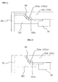
- the embodiment shown in FIG. 11 has a feature that the lower corner portions, at the extreme end of a projection projecting to the rough powder dropping port 69 of a pair of the frame members 154, 155 of an inner frame are formed with an inclined (taper) seal surface 154a (155a; the engaging surface of a corresponding receiving stand 182 is denoted by 182a) instead of the arc-shaped surface 354a (355a) of the second embodiment. Otherwise the second embodiment is similar to the above embodiments.
- the lower corner portion at the extreme ends of two projections on a pair of frame members 254, 255 of an inner frame projecting to the rough powder dropping port 69 are formed with an inclined (taper) seal surface 254a (255a; the engaging surface of a corresponding receiving stand 282 is denoted by 282a) instead of the arc-shaped surface 354a (355a) of the second embodiment, and otherwise the third embodiment is similar to that of the first embodiment.
- the portion in which the sifter net is stretched can be prepared as a limited arrangement in the same way as prior art, there can be obtained an effect that a volume of sifter frames to be prepared for replacement can be reduced and labour for a replacement job can be saved. Further, mixing of rough powder with fine powder which may be caused by the conventional shifter frame can be substantially completely prevented.
Landscapes
- Engineering & Computer Science (AREA)
- Manufacturing & Machinery (AREA)
- Combined Means For Separation Of Solids (AREA)
Applications Claiming Priority (5)
| Application Number | Priority Date | Filing Date | Title |
|---|---|---|---|
| JP24550594A JPH08108140A (ja) | 1994-10-11 | 1994-10-11 | 粉粒体篩装置に用いる多段積層式用の篩枠 |
| JP24550594 | 1994-10-11 | ||
| JP26579294 | 1994-10-28 | ||
| JP26579294A JP3479565B2 (ja) | 1994-10-28 | 1994-10-28 | 粉粒体篩装置に用いる多段積層式用の篩枠 |
| EP94308333A EP0706836B1 (de) | 1994-10-11 | 1994-11-11 | Siebkasten für Pulverteilchensieb |
Related Parent Applications (1)
| Application Number | Title | Priority Date | Filing Date |
|---|---|---|---|
| EP94308333A Division EP0706836B1 (de) | 1994-10-11 | 1994-11-11 | Siebkasten für Pulverteilchensieb |
Publications (2)
| Publication Number | Publication Date |
|---|---|
| EP1145773A2 true EP1145773A2 (de) | 2001-10-17 |
| EP1145773A3 EP1145773A3 (de) | 2001-10-24 |
Family
ID=26537265
Family Applications (2)
| Application Number | Title | Priority Date | Filing Date |
|---|---|---|---|
| EP94308333A Expired - Lifetime EP0706836B1 (de) | 1994-10-11 | 1994-11-11 | Siebkasten für Pulverteilchensieb |
| EP01115065A Withdrawn EP1145773A3 (de) | 1994-10-11 | 1994-11-11 | Siebkasten für Pulverteilchensieb |
Family Applications Before (1)
| Application Number | Title | Priority Date | Filing Date |
|---|---|---|---|
| EP94308333A Expired - Lifetime EP0706836B1 (de) | 1994-10-11 | 1994-11-11 | Siebkasten für Pulverteilchensieb |
Country Status (3)
| Country | Link |
|---|---|
| US (2) | US5598931A (de) |
| EP (2) | EP0706836B1 (de) |
| DE (1) | DE69429809T2 (de) |
Cited By (2)
| Publication number | Priority date | Publication date | Assignee | Title |
|---|---|---|---|---|
| WO2006040517A1 (en) * | 2004-10-14 | 2006-04-20 | Satake Corporation | A sieve frame |
| EP3960311A4 (de) * | 2019-04-24 | 2023-01-18 | Buhler (Wuxi) Commercial Co., Ltd. | Siebrahmen und siebvorrichtung damit |
Families Citing this family (14)
| Publication number | Priority date | Publication date | Assignee | Title |
|---|---|---|---|---|
| JP4001924B2 (ja) | 1996-08-20 | 2007-10-31 | ビューラー・アクチェンゲゼルシャフト | プランシフター |
| DE19706601C1 (de) * | 1997-02-20 | 1998-11-12 | Buehler Ag | Siebrahmen für Plansichter und Verfahren zu dessen Herstellung |
| US6672460B2 (en) * | 1997-09-02 | 2004-01-06 | Southwestern Wire Cloth, Inc. | Vibrating screen assembly with integrated gasket and frame |
| US6439392B1 (en) * | 1997-09-02 | 2002-08-27 | Southwestern Wire Cloth, Inc. | Vibrating screen assembly with tubular frame |
| US7210582B2 (en) * | 2004-05-05 | 2007-05-01 | M-I L.L.C. | Screen and screen frame for improved screen to shaker placement, handling and retention |
| WO2007061447A2 (en) * | 2005-11-15 | 2007-05-31 | Sefar Filtration Inc. | Disposable pre-tensioned sieve frame and method of making same |
| DE102006005967A1 (de) * | 2006-02-08 | 2007-08-09 | Bühler AG | Sieb |
| USD571168S1 (en) * | 2007-08-16 | 2008-06-17 | Dean Sais | Archaeological equipment sifter |
| US8679328B2 (en) * | 2012-04-10 | 2014-03-25 | Frank Hebert | Floor drain cover |
| HUE037695T2 (hu) * | 2014-02-18 | 2018-09-28 | Yukselis Makina Sanayi Ve Ticaret Anonim Sirketi | Moduláris szitadoboz |
| US10730076B2 (en) | 2018-01-19 | 2020-08-04 | Ocrim S.P.A. | Interchangeable backwire/combined sieve and dynamic combined cleaner |
| CN110280470B (zh) * | 2019-05-22 | 2021-10-01 | 江苏谷泰粮食机械科技有限公司 | 一种清粮机用粮食分筛结构 |
| CH720205A1 (de) * | 2022-11-07 | 2024-05-15 | Swisca Ag | Siebvorrichtung für Plansichter zum Fraktionieren von Getreidemahlprodukten |
| CH720204A1 (de) * | 2022-11-07 | 2024-05-15 | Swisca Ag | Siebvorrichtung für Plansichter zum Fraktionieren von Getreidemahlprodukten |
Family Cites Families (13)
| Publication number | Priority date | Publication date | Assignee | Title |
|---|---|---|---|---|
| US2068413A (en) * | 1934-11-26 | 1937-01-19 | Allan D Hunsicker | Sieve |
| US2181605A (en) * | 1936-10-21 | 1939-11-28 | William E Norvell | Separable sieve for bolters |
| FR892887A (fr) * | 1943-03-26 | 1944-05-23 | Appareil de tamisage | |
| DE892887C (de) * | 1943-10-29 | 1953-10-12 | Sack Gmbh Maschf | Blechrichtmaschine |
| US2455383A (en) * | 1947-09-16 | 1948-12-07 | Richmond Mfg Company | Screen for gyratory sifters, screens, or bolting equipment |
| US2576794A (en) * | 1948-07-19 | 1951-11-27 | William R Jost | Demountable tray sieve |
| GB705389A (en) * | 1950-03-06 | 1954-03-10 | Miag Vertriebs Gmbh | Improvements in or relating to screening frames |
| AT169734B (de) * | 1950-08-18 | 1951-12-10 | Ernst Dipl Ing Fischer | Bürstvorrichtung für Getreidemahlprodukte |
| GB720437A (en) * | 1951-09-08 | 1954-12-22 | Miag Muehlenbau & Ind Gmbh | Improvements in or relating to slide frames for vibratory sieves |
| GB883054A (en) * | 1957-11-11 | 1961-11-22 | Simon Ltd Henry | Improvements in plansifters |
| US3565251A (en) * | 1968-12-30 | 1971-02-23 | Blaw Knox Co | Plastic internal screen |
| DE4101710A1 (de) * | 1991-01-22 | 1992-07-23 | Hein Lehmann Trenn Foerder | Siebflaeche fuer eine siebmaschine |
| CH685604A5 (de) * | 1992-02-29 | 1995-08-31 | Buehler Ag | Plansichter. |
-
1994
- 1994-11-07 US US08/335,578 patent/US5598931A/en not_active Expired - Fee Related
- 1994-11-11 DE DE69429809T patent/DE69429809T2/de not_active Expired - Fee Related
- 1994-11-11 EP EP94308333A patent/EP0706836B1/de not_active Expired - Lifetime
- 1994-11-11 EP EP01115065A patent/EP1145773A3/de not_active Withdrawn
-
1996
- 1996-06-12 US US08/662,065 patent/US5664686A/en not_active Expired - Fee Related
Cited By (2)
| Publication number | Priority date | Publication date | Assignee | Title |
|---|---|---|---|---|
| WO2006040517A1 (en) * | 2004-10-14 | 2006-04-20 | Satake Corporation | A sieve frame |
| EP3960311A4 (de) * | 2019-04-24 | 2023-01-18 | Buhler (Wuxi) Commercial Co., Ltd. | Siebrahmen und siebvorrichtung damit |
Also Published As
| Publication number | Publication date |
|---|---|
| DE69429809D1 (de) | 2002-03-21 |
| EP0706836A1 (de) | 1996-04-17 |
| US5664686A (en) | 1997-09-09 |
| DE69429809T2 (de) | 2002-09-12 |
| EP0706836B1 (de) | 2002-02-06 |
| US5598931A (en) | 1997-02-04 |
| EP1145773A3 (de) | 2001-10-24 |
Similar Documents
| Publication | Publication Date | Title |
|---|---|---|
| EP1145773A2 (de) | Siebkasten für Pulverteilchensieb | |
| JP3316032B2 (ja) | 粉粒体篩機用の篩枠 | |
| US6202857B1 (en) | Frame for flat sifter and process for producing the same | |
| CA2988348C (en) | Method and apparatuses for screening | |
| US9884345B2 (en) | Method and apparatuses for screening | |
| CA2469352A1 (en) | A screen assembly for a vibratory separator | |
| JP2019533573A (ja) | 振動ふるいのための装置、方法、およびシステム | |
| US9144825B2 (en) | Method and apparatuses for screening | |
| US8261915B2 (en) | Screening machine and associated screen panel | |
| AU701165B2 (en) | Convertible kits for a material separating apparatus | |
| CN210045556U (zh) | 一种振动筛 | |
| CN106232245A (zh) | 模块化筛分盒 | |
| JP3479565B2 (ja) | 粉粒体篩装置に用いる多段積層式用の篩枠 | |
| CN209791965U (zh) | 一种粉末震动筛 | |
| CA2583757A1 (en) | A sieve frame | |
| JP3836972B2 (ja) | 振動ふるい機 | |
| CN115625111A (zh) | 振动散料筛分设备、振动散料分拣系统及物料筛选分拣方法 | |
| US2865506A (en) | Separators for pulverulent materials | |
| JP3612825B2 (ja) | 篩機の篩網枠 | |
| JP2001300426A (ja) | 篩枠ユニットを多段積層した粉粒体篩装置 | |
| CN120152792A (zh) | 用于对谷物研磨产品进行分级的平筛的筛分装置 | |
| GB2073618A (en) | Vibratory screening panels | |
| US2899059A (en) | Vibrating screens | |
| CN101378848A (zh) | 筛选器 | |
| JPH08108140A (ja) | 粉粒体篩装置に用いる多段積層式用の篩枠 |
Legal Events
| Date | Code | Title | Description |
|---|---|---|---|
| PUAI | Public reference made under article 153(3) epc to a published international application that has entered the european phase |
Free format text: ORIGINAL CODE: 0009012 |
|
| PUAL | Search report despatched |
Free format text: ORIGINAL CODE: 0009013 |
|
| AC | Divisional application: reference to earlier application |
Ref document number: 706836 Country of ref document: EP |
|
| AK | Designated contracting states |
Kind code of ref document: A2 Designated state(s): CH DE GB LI |
|
| AK | Designated contracting states |
Kind code of ref document: A3 Designated state(s): CH DE GB LI |
|
| RAP1 | Party data changed (applicant data changed or rights of an application transferred) |
Owner name: NISSHIN SEIFUN GROUP INC. |
|
| RAP1 | Party data changed (applicant data changed or rights of an application transferred) |
Owner name: NISSHIN FLOUR MILLING INC. |
|
| 17P | Request for examination filed |
Effective date: 20020306 |
|
| AKX | Designation fees paid |
Free format text: CH DE GB LI |
|
| 17Q | First examination report despatched |
Effective date: 20030227 |
|
| STAA | Information on the status of an ep patent application or granted ep patent |
Free format text: STATUS: THE APPLICATION IS DEEMED TO BE WITHDRAWN |
|
| 18D | Application deemed to be withdrawn |
Effective date: 20030910 |