EP0706836A1 - Siebkasten für Pulverteilchensieb - Google Patents
Siebkasten für Pulverteilchensieb Download PDFInfo
- Publication number
- EP0706836A1 EP0706836A1 EP94308333A EP94308333A EP0706836A1 EP 0706836 A1 EP0706836 A1 EP 0706836A1 EP 94308333 A EP94308333 A EP 94308333A EP 94308333 A EP94308333 A EP 94308333A EP 0706836 A1 EP0706836 A1 EP 0706836A1
- Authority
- EP
- European Patent Office
- Prior art keywords
- frame
- sifter
- rough
- fine powder
- powder
- Prior art date
- Legal status (The legal status is an assumption and is not a legal conclusion. Google has not performed a legal analysis and makes no representation as to the accuracy of the status listed.)
- Granted
Links
- 239000000843 powder Substances 0.000 title claims abstract description 407
- 239000002245 particle Substances 0.000 title claims description 34
- 238000007789 sealing Methods 0.000 claims abstract description 17
- 238000005192 partition Methods 0.000 claims description 58
- 239000000463 material Substances 0.000 claims description 3
- 230000002093 peripheral effect Effects 0.000 claims 2
- 238000007599 discharging Methods 0.000 claims 1
- 239000011236 particulate material Substances 0.000 claims 1
- 230000000694 effects Effects 0.000 abstract description 7
- 230000006835 compression Effects 0.000 abstract description 3
- 238000007906 compression Methods 0.000 abstract description 3
- 230000000295 complement effect Effects 0.000 abstract 1
- 239000002023 wood Substances 0.000 description 29
- 230000003014 reinforcing effect Effects 0.000 description 20
- 235000013312 flour Nutrition 0.000 description 16
- 238000000638 solvent extraction Methods 0.000 description 16
- 239000000203 mixture Substances 0.000 description 15
- 238000003825 pressing Methods 0.000 description 10
- 238000012856 packing Methods 0.000 description 7
- 230000033001 locomotion Effects 0.000 description 6
- 230000000881 depressing effect Effects 0.000 description 5
- 239000002184 metal Substances 0.000 description 5
- 229910001220 stainless steel Inorganic materials 0.000 description 5
- 239000010935 stainless steel Substances 0.000 description 5
- 230000009545 invasion Effects 0.000 description 4
- 239000004745 nonwoven fabric Substances 0.000 description 4
- 238000012360 testing method Methods 0.000 description 4
- 238000005452 bending Methods 0.000 description 3
- 230000000994 depressogenic effect Effects 0.000 description 2
- 238000009434 installation Methods 0.000 description 2
- 238000000034 method Methods 0.000 description 2
- 238000000926 separation method Methods 0.000 description 2
- 229920002472 Starch Polymers 0.000 description 1
- 230000015572 biosynthetic process Effects 0.000 description 1
- 239000000919 ceramic Substances 0.000 description 1
- 238000005520 cutting process Methods 0.000 description 1
- 238000004519 manufacturing process Methods 0.000 description 1
- 238000003801 milling Methods 0.000 description 1
- 238000012986 modification Methods 0.000 description 1
- 230000004048 modification Effects 0.000 description 1
- 230000002787 reinforcement Effects 0.000 description 1
- 239000011347 resin Substances 0.000 description 1
- 229920005989 resin Polymers 0.000 description 1
- 238000009751 slip forming Methods 0.000 description 1
- 125000006850 spacer group Chemical group 0.000 description 1
- 239000008107 starch Substances 0.000 description 1
- 235000019698 starch Nutrition 0.000 description 1
Images


Classifications
-
- B—PERFORMING OPERATIONS; TRANSPORTING
- B07—SEPARATING SOLIDS FROM SOLIDS; SORTING
- B07B—SEPARATING SOLIDS FROM SOLIDS BY SIEVING, SCREENING, SIFTING OR BY USING GAS CURRENTS; SEPARATING BY OTHER DRY METHODS APPLICABLE TO BULK MATERIAL, e.g. LOOSE ARTICLES FIT TO BE HANDLED LIKE BULK MATERIAL
- B07B1/00—Sieving, screening, sifting, or sorting solid materials using networks, gratings, grids, or the like
- B07B1/46—Constructional details of screens in general; Cleaning or heating of screens
- B07B1/4609—Constructional details of screens in general; Cleaning or heating of screens constructional details of screening surfaces or meshes
- B07B1/4618—Manufacturing of screening surfaces
-
- B—PERFORMING OPERATIONS; TRANSPORTING
- B07—SEPARATING SOLIDS FROM SOLIDS; SORTING
- B07B—SEPARATING SOLIDS FROM SOLIDS BY SIEVING, SCREENING, SIFTING OR BY USING GAS CURRENTS; SEPARATING BY OTHER DRY METHODS APPLICABLE TO BULK MATERIAL, e.g. LOOSE ARTICLES FIT TO BE HANDLED LIKE BULK MATERIAL
- B07B1/00—Sieving, screening, sifting, or sorting solid materials using networks, gratings, grids, or the like
- B07B1/28—Moving screens not otherwise provided for, e.g. swinging, reciprocating, rocking, tilting or wobbling screens
- B07B1/38—Moving screens not otherwise provided for, e.g. swinging, reciprocating, rocking, tilting or wobbling screens oscillating in a circular arc in their own plane; Plansifters
-
- B—PERFORMING OPERATIONS; TRANSPORTING
- B07—SEPARATING SOLIDS FROM SOLIDS; SORTING
- B07B—SEPARATING SOLIDS FROM SOLIDS BY SIEVING, SCREENING, SIFTING OR BY USING GAS CURRENTS; SEPARATING BY OTHER DRY METHODS APPLICABLE TO BULK MATERIAL, e.g. LOOSE ARTICLES FIT TO BE HANDLED LIKE BULK MATERIAL
- B07B1/00—Sieving, screening, sifting, or sorting solid materials using networks, gratings, grids, or the like
- B07B1/46—Constructional details of screens in general; Cleaning or heating of screens
-
- B—PERFORMING OPERATIONS; TRANSPORTING
- B07—SEPARATING SOLIDS FROM SOLIDS; SORTING
- B07B—SEPARATING SOLIDS FROM SOLIDS BY SIEVING, SCREENING, SIFTING OR BY USING GAS CURRENTS; SEPARATING BY OTHER DRY METHODS APPLICABLE TO BULK MATERIAL, e.g. LOOSE ARTICLES FIT TO BE HANDLED LIKE BULK MATERIAL
- B07B2201/00—Details applicable to machines for screening using sieves or gratings
- B07B2201/02—Fastening means for fastening screens to their frames which do not stretch or sag the screening surfaces
Definitions
- the present invention relates to a sifter frame used as a sifter for separating the particle sizes of powder particles such as flour and the like, and more specifically, but not exclusively, to a structure of an intimate contact type sifter frame used by being stacked into multi-stages to sift and separate powder particles.
- Sifters are conventionally used to separate the particle sizes of powder particles such as flour and the like. The sifter will be described below with respect to the separation of the particle sizes of flour by way of example.
- Sifter types known as plan sifter, square sifter and the like are used in the flour milling industry from old times to separate the particle sizes of flour, and at present various types of sifters such as the modifications of the above sifters and intermediate type sifters (such as a junior type sifter and the like) are put into practical use. These sifters are fundamentally arranged such that powder having a small particle size in powder supplied onto the sifter is caused to pass through the sifter downwardly while a multiplicity of stacked sifter frames are caused to make a circular motion to separate the particle sizes of the supplied powder.
- a reason why the flour sifter is composed of the sifter frames stacked to the multi-stages as described above is to make the sifter area as large as possible, which is desirable to effectively separate flour by moving the flour on the surface of the sifter.
- the area of the sifter per unit area of installation is increased to save the installation area in such a manner that the sifter is composed to sifter frames stacked to the multi-stages and a sifter surface on which flour moves is formed so that the sifter surface vertically meanders in the sifter.
- the sifter is usually composed of a group of stacked square sifter frames tightened from the upper and lower sides thereof or a group of sifter frames which are stacked to ten to twenty stages and accommodated in a sifter frame box called a box so that they are horizontally tightened and fixed and also tightened and fixed from the upper side thereof. Then, the box and the like are driven by a drive unit composed of an eccentric shaft provided with a balance weight and a drive shaft to make a circular motion within a horizontal plane at high speed.
- sifter frame which has a structure for limiting a portion to be replaced only to a sifter net. That is, there are generally used a pair of a frame member of about 1 m x 1 m (referred to as an outer frame) and a frame member having a sifter net stretched therein as an object to be replaced (referred to as an inner frame) with the inner frame being engaged with the outer frame.
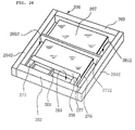
- the conventional type sifter frame shown in these figures has a combination type structure arranged such that a rectangular inner frame 500 (refer to FIG. 32) is fitted within the inner frame fitting portion of an outer frame 600 (refer to FIG. 33), the inner frame 500 having a sifter net 501 stretched over the upper surface thereof to separate flour to powder on a sifter (rough powder) and powder below the sifter (through: fine powder), and the outer frame 600 being in contact with the three circumferential sides of the inner frame and having a longitudinal path in an upward/downward direction (refer to FIG. 34).
- the above inner frame 500 shown in FIG. 32 is composed of wood frame member 502 - 505 of, for example, wood for constituting a rectangular four-side frame and a sifter net 501 having a predetermined sifting mesh and stretched over reinforcing wood bars 506, 507 formed to a cross shape and disposed inwardly of the rectangular frame member.
- a crimp net having a rough mesh is usually stretched below the sifter net 501 in parallel therewith and a cleaner such as, for example, a triangular flat cleaner having a hemispheric projection is movably interposed between the upper and lower nets so that clogging of the sifter net 501 is prevented by causing the cleaner to beat the net when the sifter is in operation.
- a cleaner such as, for example, a triangular flat cleaner having a hemispheric projection
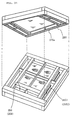
- the outer frame 600 shown in FIG. 33 is composed of an inner frame fitting portion within which the above inner frame 500 is fitted in contact with or biased to an outer side wall outer block member 610 as one of the four sides of the rectangular frame forming the outer block of the outer frame 600 and longitudinal paths 601, 602, 602 disposed outwardly of the inner frame fitting portion in an upward/downward direction along the inside of each of the remaining three sides except the side wall 610 of the above one side.
- the outer frame 600 is composed of a pair of parallel inner side walls (frame members) 607, 607 disposed to form the above inner frame fitting portion, three inner frame fitting stand frames 604, 605, 606 fixed over the lower surfaces of the inner side walls 607, 607.
- a pair of outer side walls 608, 608 is disposed separately to form the fine powder dropping ports 602, 602 to the outside of each of the above outer inside walls 607, 607, and the outer side wall 610 is disposed in contact with the outside of the inner frame fitting stand frame 606.
- An outer side wall 609 is separately disposed to form a rough powder dropping port 601 (usually, called an over port) outwardly of the inner frame fitting stand frame 604, and a receiving plate (fine powder flowing plate) 603 is provided as a bottom surface for introducing fine powder (through) having passed through the sifter net 501 of the inner frame to be fitted to the above right and left dropping ports 602, 602.
- the inner side walls 607, 607 are fixed to the outer side walls 608, 608 at suitable positions through intermediate brackets 613, 613, and the inner frame fitting stand frame 604 is fixed to the outer side wall 609 through an intermediate bracket 615 in the same way.
- Numeral 614 denotes blocks disposed at four corners to close the unnecessary space portions in the outer frame as well as to increase the strength of a fitting structure in an upward/downward direction.
- the receiving plate 603 is composed of a stainless steel sheet or the like fixed to the respective lower surfaces of the above inner frame fitting stand frames 604, 605, 606 by screws. With this arrangement, each of the right and left ends of the receiving plate 603 has a gap corresponding to the thickness of the stand frames 604, 605 between the lower surface of the inner side wall 607 and the receiving plate 603, and these gaps form slit-shaped fine powder dropping ports 617 for dropping fine powder dropped onto the receiving plate 603 into the right and left fine powder dropping ports 602. Note, the receiving plate 603 is disposed substantially at the intermediate position in the upward-downward direction of the sifter frame in a bottom-lifted-state (refer to FIG. 35).
- a direction in which a pair of the fine powder dropping ports 602 is separated from each other is referred to as a right/left direction and a direction orthogonal to the right/left direction in a horizontal direction is referred to as a forward/backward direction.
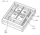
- a group of the sifter frames having the above arrangement can be constructed by stacking a multiplicity of the sifter frames in such a manner that the positions of the rough powder dropping ports 601 are successively reversed (alternately disposed) on the respective stages (refer to FIG. 35). Then, powder particles-having moved (flown) on the sifter net 501 of a certain stage drop into the rough powder dropping port 501 of the inner frame 5 along the inclined surface 502a of the frame member 502 in contact with the rough powder dropping port 601 and moves onto the sifter net of the sifter frame of the next lower stage. Further, fine powder having passed through the sifter net 501 drops onto the receiving plate 603 and further drops into the fine powder dropping ports 602 through the right and left slit-shaped fine powder dropping port 617.
- press beams 620, 620 are disposed between the outer side walls 609, 610 below the receiving plate 603 of the outer frame 600 so that the press beams 620, 620 extend to the upper surfaces of the inner side wall 607 and the frame member 504 (or 505) of the inner frame of the lower stage sifter frame to cover them in contact therewith (refer to FIG. 35).
- the sifter is naturally required to securely prevent the mixture of rough powder with fine powder caused through the gap defined at the inner frame fitting position.
- the lower portion of the frame member 502 of the inner frame 500 is provided with a stepped portion as shown in FIG. 34 (b) and the stepped leg portion 502b is engaged with the stepped portion 604a of the inner frame fitting stand frame 604 formed in correspondence with the outer frame to form seal portions.
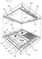
- FIG. 34 (a) is an unfolded view for explaining the relationship between the outer frame 600 and the inner frame 500 fitted therewith
- FIG. 35 is an unfolded view for explaining a state that the sifter frames each arranged as described above are stacked with the rough powder dropping ports 601 thereof successively disposed alternately.
- surfaces 700, 701 shown cross-hatched serve as seal surfaces for strongly pressing the inner frame 500 of the lower stage sifter frame downwardly by the upper stage sifter frame (outer frame 600) so as to increase the seal pressure of the above seal portions and at the same time to seal and partition a region (rough powder region) where rough powder flows from a region where fine powder flows (fine powder region).
- a suitable seal sheet is applied to the surfaces 700, 701 as necessary.
- the inventors have found the following fact by examining a cause of the mixture of rough powder with fine powder, taking the present state mentioned above into consideration. That is, there is a problem that although the mixture of rough powder with fine powder in the conventional sifter frame is not caused on the above seal surfaces 700, 701 which are in intimate contact with each other under pressure, the mixture of them is caused at the portion where the frame member 502 is fitted with the inner frame fitting stand frame 604.
- brackets 616 provided to form the inner frame fitting portion of the outer frame are engaged with the extreme (front) end surfaces (surfaces facing to the rough powder dropping port) 504a, 505a of the right and left frame members 504, 505 of the inner frame to seal a fine powder region and a rough powder region, no pressure is applied to make the intimate contact of the both surfaces of the fitting portion in the structure. More specifically, the direction of a horizontal force for causing the both surfaces to come into intimate contact with each other is different 90° from a vertical force for causing the upper and lower sifter frames to come into intimate contact with each other.
- the rough powder having entered the above gap further moves and enters the fine powder region as shown by dotted lines 802, 803, by which the aforesaid mixture is caused.
- Preferred embodiments of thee present invention provide a novel powder separating sifter frame, alleviating the above various problems, and capable of reducing the storing volume by limiting the portion of the sifter frame to be prepared and stored, as well as satisfying a requirement for saving labor needed by a replacement job, and securely preventing the mixing of rough powder with fine powder, which has been sometimes caused by a conventional sifter frame.
- a sifter frame having preferred features of the present invention is described below.
- a first feature of the present invention resides in the arrangement that a sifter frame for a powder particle shifter comprises an inner frame and an outer frame, the inner frame being formed to a rectangular four-side shape by outer block frame members each having the same height and having a sifter net stretched over the upper surface of the inner region surrounded by the outer block frame members; the outer frame being formed to a rectangular four-side shape by outer block frame members each having the same height and including each of fine powder dropping ports opened in an upward/downward direction along both inner sides of a pair of the confronting sides of the outer block frame members, a rough powder dropping port opened in an upward/downward direction along the inside of one of the other pair of the confronting sides, and a rectangular fine powder receiving plate horizontally disposed at a position of intermediate height in the region surrounded by the three ports and the other of the other pair of the confronting sides wherein the space on the receiving plate enables fine powder on the receiving plate to be dropped into the fine powder dropping ports but being partitioned from the rough powder dropping port by
- seal surfaces of the inner frame and the outer frame are kept to a good seal state by being applied with an intimate contact seal sheet.
- a sheet suitable for the intimate seal includes non-woven fabric, felt, an elastic seal packing material and the like.
- the above seal surface is formed such that, for example, an upper flange having the same height and projecting outward is annularly and continuously formed to the outer side wall (outside circumference) of the outer block frame members of the inner frame and a downward seal surface is formed on the lower surface of the upper flange.
- the outer frame is provided with a stepped portion to be engaged with the stepped portion of the inner frame and the above upward seal surface is formed to the surface of the stepped portion confronting the lower surface of the upper flange.
- a second feature of the present invention resides in the arrangement that a sifter frame for a powder particle shifter composed of a pair of an outer frame and an inner frame, the outer frame having an outer block formed to a rectangular four-side shape by outer block frame members each having the same height and including in the inside of the outer block each of a pair of fine powder dropping ports opened in an upward/downward direction along both inner sides of a pair of the confronting sides of the rectangular four sides, a rough powder dropping port opened in an upward/downward direction along the inside of one of the other pair of the confronting sides, outer block frame members constituting the sides opposite to the other pair of the confronting sides, and a rectangular fine powder receiving plate horizontally disposed at a position of intermediate height in the region surrounded by the rough powder dropping port and the fine powder dropping ports wherein the space on the receiving plate enables fine powder on the receiving plate to be dropped into the fine powder dropping ports but being partitioned from the rough powder dropping port by a partition wall; and the inner frame being formed to a substantially rectangular four-side shape
- an intimate contact (air tight) seal sheet is applied to any of the arc-shaped or inclined engaging surfaces where the projected portions of the outer block frame members of the inner frame are engaged with the receiving portion formed to the outer frame on which the projected portions are to be placed.
- the aforesaid sheets are also suitable for the intimate contact seal.
- the side surface of the inner frame where the outer block frame members in contact with the rough powder dropping port faces to the rough powder dropping port is formed to be flush with the side surface of the outer frame where the partition wall partitioning the space on the receiving plate of the outer frame from the rough powder dropping port faces to the rough powder dropping port, as well as a shield sheet member for covering up to the side surface of the outer frame is formed to the side surface of the inner frame.
- the sifter frames of this example are used by being stacked to multi-stages, and it is needless to say that a seal member is provided to the lower surface of the sifter frame of the upper stage in the same way as prior art, the seal member extending to and air-tightly engaging with the upper surfaces of the frame members of both sides which are in contact with the engaging surfaces (engaging surfaces confronting in a horizontal direction) of the sifter frame of the lower stage formed by the inner frame fitted with the outer frame.
- a seal member is provided to the lower surface of the sifter frame of the upper stage and extends to and engages with the upper surfaces of the outer block frame members of the inner frame and the reinforcing members of the outer frame so that powder does not pass onto the sifter net of the inner frame from a gap between the engaging surfaces where the outer block frame members of the inner frame in contact with the fine powder dropping ports are engaged with the reinforcing members of the outer frame in contact with the outer sides of the outer block frame members of the inner frame.
- a sheet suitable for intimate contact seal to the lower surface of the seal member (or to the surface engaging with the seal member).
- non-woven fabric, felt, an elastic seal packing material and the like are used similarly to the above.
- the reinforcing members of the outer frame may be omitted when there is no problem with respect to the strength of structure.
- a third feature of the present invention resides in the arrangement that a sifter frame for a powder particle shifter composed of a pair of an outer frame and an inner frame, the outer frame being formed to have an outer block of a rectangular four-side shape by the combination of outer block frame members each having the same height and a receiving plate to include in the inside of the outer block each of a pair of fine powder dropping ports opened in an upward/downward direction along the inside of each of a pair of the confronting sides of the rectangular four sides, a rough powder dropping port opened in an upward/downward direction along the inside of one of the other pair of the confronting sides, outer block frame members constituting sides opposite to the other pair of the confronting sides, a rectangular fine powder receiving plate horizontally disposed at a position of intermediate height in the region surrounded by the rough powder dropping port and the fine powder dropping ports, and an inner frame fitting portion above the receiving plate and the rough powder dropping port; and the inner frame formed to a rectangular shape to be fitted with the inner frame fitting portion formed to the outer frame without producing substantially no gap there
- the lower surface of the sifter frame stacked to the upper stage in such a manner that the lower surface extends to and air-tightly engages with both upper surfaces of the outer frame and the inner frame which are formed by being fitted with the sifter frame stacked to the lower stage.
- a fourth feature of the present inventions resides in the arrangement that a sifter frame for a powder particle shifter composed of a pair of a lower frame and an upper frame, the lower frame being formed to have an outer block of a rectangular four-side shape by the combination of outer block frame members each having the same height and a receiving plate to include in the inside of the outer block each of a pair of fine powder dropping ports opened in an upward/downward direction along the inside of each of a pair of the confronting sides of the rectangular four sides, a rough powder dropping port opened in an upward/downward direction along the inside of one of the other pair of the confronting sides, outer block frame members constituting sides opposite to the other pair of the confronting sides, a rectangular fine powder receiving plate horizontally disposed at a position of intermediate height in the region surrounded by the rough powder dropping port and the fine powder dropping ports, and an inner frame fitting portion above the receiving plate and the rough powder dropping port; and the upper frame including each of a rectangular sifter net portion having a sifter net stretched over the ceiling
- positioning means such as, for example, a plurality of projectedly/recessedly formed fitting portions to be fitted with each other, or the like on the surfaces where the upper frame is vertically engaged with the lower frame to prevent the horizontal dislocation of them.
- the rough powder region can be partitioned from the fine powder region to such a strict degree which does not require to take a leakage portion into consideration.
- the mixture of fine powder with rough powder can be securely prevented.
- the weight and size of the inner frame can be reduced as compared with those of an inner frame arranged integrally as a whole.
- the seal surfaces for partitioning and sealing the rough powder region from the fine powder region are formed as the closed type rectangularly annular edges located on the same horizontal surface and further an upward/downward intimate contact force acts on the arc-shaped or inclined engaging seal surfaces in the seal surfaces of the inner frame and the outer frame in the vicinity of the rough powder dropping port, the rough powder region can be strictly partitioned and sealed from the fine powder region.
- the weight and size of the inner frame can be reduced as compared with those of an inner frame arranged integrally as a whole.
- the seal surfaces for partitioning and sealing the rough powder region from the fine powder region are formed as the closed type rectangularly annular edges located on the same plane and an upward/downward intimate contact force acts on the seal surfaces, a strictly partitioned seal can be achieved which need not to take the leakage between the rough powder region and the fine powder region into consideration.
- the weight and size of the upper frame can be reduced as compared with those of an upper frame arranged integrally as a whole.
- the frame members of the upper frame may be formed to a shape which is substantially in coincidence with the shape of the frame members of the lower frame so that the engaging surfaces in an upward/downward direction of the frame members necessary to partition and seal the rough powder region from the fine powder region can be easily prepared, the partitioned seal can be kept in a good state.
- the partitioning structure for partitioning the rough powder region from the fine powder region can be arranged by the frame members of the inner frame or the outer frame itself and these regions can be sealed only by the intimate contact of the horizontal seal surfaces which are engaged in an upward/downward direction, the above partitioning structure does not have the seal structure of prior art which contains a vertically sealed surface as shown in FIG. 32 - FIG. 36. Consequently, there can be obtained a good partitioned seal by which a possibility that rough powder is mixed with fine powder is securely prevented.
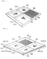
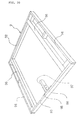
- FIG. 1 and FIG. 2 show the structure of an inner frame 305 of the embodiment 305 having a sifter net 351 stretched therein.
- the inner frame 305 is composed of a rectangular four-side frame formed by outer block frame members 352, 352a and the sifter net 351 is stretched over the frame and reinforcing wood bars 353 formed to a cross shape in the rectangular frame.
- a crimp net is stretched in parallel with the sifter net 351 and a cleaner is movably interposed therebetween (neither shown) to prevent the clogging of the net in a similar way as in the prior art.
- the inner frame 305 of the embodiment has the following features. That is, the frame members 352, 352a have upper flanges 354, 354a which project outwardly of the circumference thereof and are annularly continued over the rectangular four sides as a whole on the upper portions (lower portions in FIG. 2 showing the inverted view thereof) of the frame members 352, 352a at the same height.
- the downward surfaces of the upper flanges 354, 354a (upward surfaces in FIG. 2 showing the inverted view thereof) have intimate contact sheets 355, 355a applied thereto to form downward seal surfaces 370, 370a.
- the frame member 352a at a position where rough powder on a sifter is dropped into a rough powder dropping port 361 of an outer frame to be described below has a cross sectional area larger than those of the other frame members.
- a reason why the frame member 352a has such a larger cross sectional area is to securely provide a seal on the seal surface 570a by increasing the bending rigidity of the frame member 352a by increasing the modulus of section thereof.
- the frame member 352a,excluding the upper flange 354a has a width which is set larger than that of the other frame members 352 and has a height for enabling the lower end of the frame member 352a to come into contact with the receiving plate of the outer frame to be described below.
- the frame member 352a has an inclined surface 352b formed thereon, as in the prior art, so that rough powder on the sifter net 351 is liable to drop into the rough power dropping port.
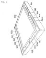
- FIG. 3 - FIG. 5 show the outer frame 306 of the embodiment whose arrangement is substantially the same as that of the conventional sifter frame except the structure of the frame portion within which the above inner frame 305 is internally fitted. That is, the outer frame 306 is composed of a rectangular (square in the embodiment) four-side frame including a pair of confronting inner partition walls 366, a pair of outer side walls 367 disposed outwardly of the inner partition walls 366 and forming fine powder dropping ports 362 together with the inner partition walls 366, another pair of confronting outer side walls 368, and a receiving plate 363 as a fine powder flowing plate for introducing fine powder (through) having passed through the sifter net 351 of the inner frame 305 to the fine powder dropping port 362.
- Numeral 365 denotes intermediate brackets for connecting the inner partition walls 366 to the outer side walls 367, 368.
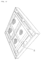
- the receiving plate 363 of the embodiment is composed of a rectangular stainless steel sheet fixed to the lower surfaces of three parallel wood bars 364 by screws, and these three wood bars 364 are disposed as described below. That is, as shown in FIG. 3 - FIG. 5 (particularly refer to FIG. 5 showing a view observed from the inside opposite to FIG. 3), the first wood bar 364a is a square bar having a predetermined height adjacent to the rough powder dropping port 361 of FIG. 3 and has upper corners at the ends in the longitudinal direction thereof each stepped by cutting out a piece at a predetermined height.
- the second wood bar 364b at the center is provided as a square bar having a height corresponding to the lower step portion of the first wood bar 364a.
- the third wood bar 364c on the opposite side is composed of a stepped square bar having a lower step whose height corresponds to the lower step portion of the first wood bar 364a and an upper step whose height corresponds to the total height of the first wood bar 364a with the lower step directed inwardly.
- a square bar 364d which has such a size that the upper surface thereof is flush with the top surfaces of the first and third wood bars 364a, 364c, is disposed from the step portion of each of the ends of the first wood bar 364a to each of the lower steps of the third wood bar 364c while coming into contact with the upper surface of the second wood bar 364b. Consequently, there are formed rectangularly annular seal surfaces 371a, 371c, 371d which are positioned on the same plane as a whole.
- numeral 369 denotes slit-shaped fine powder dropping ports defined between the receiving plate and the inner partition walls 366.
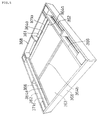
- the frame portion composed of the inner partition walls 366 and the receiving plate 363 as described above is supported by the inner partition walls 366 located under the receiving plate and support bars 366a separately disposed in parallel with each other in an upward/downward direction at a predetermined height from the lower surface of the outer frame (particularly refer to FIG. 4 observing the outer frame from the lower side thereof), whereby a space is formed on the lower side of the receiving plate 363 to enable rough powder to flow on the sifter net of a lower stage.
- FIG. 6 shows how the inner frame 305 is fitted within the frame portion of the outer frame 306 each arranged as described above. More specifically, the stepped lower portion of the inner frame 305 is fitted within the inside of the frame portion formed by the receiving plate 363, the inner partition walls 366 and the like, so that the seal surfaces 370, 370a of the lower surfaces of the upper flanges 354, 354a come into contact with the respective seal surfaces 371a, 371c, 371d of the outer frame 306.
- annular seal surfaces 370, 370a which are located on the same plane, of the inner frame 305 come into contact with the annular seal surfaces 371a, 371c, 371d, which are located on the same plane, of the outer frame 306 confronting the inner frame 305.
- the seal surfaces in contact with each other are caused to firmly come into contact with each other under pressure, whereby a rough powder region is securely partitioned and sealed from a fine powder region.
- the rough powder drops onto the sifter net of the next stage from the rough powder dropping port 361 after moving over the sifter net 351, then moves on the sifter net 351 of the next stage to the rough powder dropping port 361 located on the opposite side and further drops onto the sifter net of the next stage. Then, the rough powder is discharged to the outside of the system through the lowermost sifter frame while meandering with the successive repetition of the above operation.
- fine powder having passed through the sifter nets 351 of the respective stages drops onto the receiving plate 363, then drops into the fine powder dropping ports 362 from the right and left slit-shaped fine powder dropping ports 369 and is introduced to a fine powder collection path.
- the seal surfaces for partitioning and sealing the rough powder region from the fine powder region are formed as closed curve type annular surfaces located on the same plane, portions on which an contact pressure applying force does not act, which is found in prior art, do not exist anywhere, so that an intimate contact seal can be securely realized.
- the sifting and separating operation effected using the sifter frames of the embodiment is not limited to flour but applicable to the separation of any appropriate powder particles such as starch, ceramics and the like (which is applicable to embodiments to be described below).
- numeral 5 in FIG. 8 and FIG. 9 denotes an inner frame composed of a substantially rectangular four-side frame formed from outer block frame members 52, 53, 54, 55 each composed of, in the embodiment, a wood square column member and sifter net region 50 is formed in the inner frame 5.
- Reinforcing wood bars 56, 57 formed to a cross shape are disposed between the frame members 52 and 53 and the frame members 54 and 55 respectively, and a sifter net 51 is stretched over the top surfaces of the frame members 52, 53, 54, 55 and the reinforcing wood bars 56, 57.
- the frame members 52 - 55 are arranged such that the upper surfaces thereof are flush with the lower surfaces thereof as well as the frame member 52 is composed of a square column member having a larger cross sectional area so that the frame member 52 has a modulus of section larger than those of the other three frame members 53 - 55.
- a reason why the upper surfaces of the inner frame is formed to have the same level is to make surfaces, which are to be sealed when sifter frames are stacked to multi-stages, flat.
- a reason why the frame member 52 is composed of the square column member having a cross sectional area larger than those of the other three frame members is that a maximum bending rigidity is required for the frame member 52.
- One of the features of the inner frame 5 of the embodiment is that when the inner frame 5 is fitted within an outer frame to be described later, a thin flat metal bar 58 is fixed to the front side surface of the frame member 52 which is to be in contact with a rough powder dropping port (69 to be described later) by means of screws or the like and further that the lower end of the flat bar 58 projects downwardly of the lower surface of the frame member 52 by a predetermined distance (refer to FIGS. 8, 9).
- the flat metal bar 58 is mounted on the front side surface of the frame member 52 in the embodiment to securely prevent the invasion of rough powder into fine powder through engaging surfaces where the frame member 52 of the inner frame engages the receiving stand (68 to be described later) of the outer frame. This is provided to position the frame member 52 thereon in such a manner that the meeting line of the above engaging surfaces facing the rough powder dropping port is covered with the flat metal bar 58 as described above.
- a packing may be interposed between the flat bar 58 and the frame member 52.
- the embodiment employs a characteristic arrangement that the extreme (front) ends of the right and left frame members 54, 55, which are to be in contact with fine powder dropping ports (65 to be described later) when the inner frame 5 is fitted within the outer frame to be described later, project towards the rough powder dropping port side, beyond position of the frame member 52, and the lower corner portions of the extreme (front) ends of the right and left frame members 54, 55 have convex arc-shaped surfaces 54a, 55a.
- elastic seal packing members 88 each having a predetermined uniform thickness are applied to the convex arc-shaped surfaces 54a, 55a and the lower surface of the frame member 52 shown by cross-hatching.
- the above arrangement is employed in the embodiment to form seal surfaces on which a compression force (depressing force) acts in a generally vertical direction while enabling the easy and smooth mounting and dismounting of the inner frame on and from the outer frame in such a manner that the lower corner portions at the extreme ends of the frame members 54, 55 are formed to the convex arc-shaped surfaces 54a, 55a engaged with the concave arc-shaped surfaces 82a, 82a of the outer frame corresponding thereto in order to that the invasion of rough powder into a fine powder region from the rough powder dropping port is securely prevented.
- the elastic seal packing members are applied to further improve the sealing property of the engaging surfaces.
- the sifter frame of the embodiment is similar to the conventional sifter frame except the above characteristic arrangement, and, for example, a crimp net may be stretched in the vicinity of the lower side of the sifter net 51 in parallel therewith with a cleaner ( neither shown) movably interposed between the nets to prevent the clogging of the net.
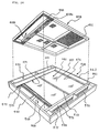
- FIG 10 and FIG. 11 show the outer frame 6 constituting the sifter frame of the embodiment.
- the outer frame 6 is a rectangular four-sided frame, formed by outer side walls (outer block members) 62, 63, 64, 64 each composed of a wood sheet.
- a pair of inner side walls 61, 61 each composed of a flat metal bar are disposed between the outer side walls 62, 63 spaced apart from the outer side walls 64, 64 in parallel therewith so that the fine powder dropping ports 65, 65 are defined to the inside of a pair of the confronting outer side walls 64, 64 of the above outer side walls 62, 63, 64, 64, and further a pair of receiving stands (inner frame extreme end projection receiving stands) 82, 82 each composed of a resin member are disposed at the both ends (inside surfaces of the inner side walls 61, 61) of the rough powder dropping port 69 formed to the inside of the outer side wall 62.
- the receiving stands 82, 82 are provided with the concave arc-shaped surfaces 82a, 82a to and with which the convex arc-shaped surfaces 54a, 55a of the lower corner portions of the extreme ends of the frame members 54, 55 of the aforesaid inner frame 5 correspond and are engaged.
- a recessed portion 60 into and with which the above inner frame 5 is inserted and fitted substantially in close contact therewith is formed by the outer side wall 63, a pair of the inner side walls 61, 61 and a pair of the receiving stands 82, 82.
- numeral 68 denotes a partition wall for partitioning a fine powder receiving region provided with a receiving plate 67 from the rough powder dropping port 69 defined to the inside of the outer side wall 62 and the partition wall 68 also serves as a receiving plate on which the frame member 52 of the inner frame is to be place.
- the rough powder dropping port 69 is formed as a space region surrounded by the partition wall 68, a pair of the receiving stands 82 and the outer side wall 62 in parallel with the partition wall 68 and passing through in a generally vertical direction.
- the fine powder receiving region is formed in such a manner that inner frame receiving stands 73, 74 each composed of a wood bar as high as the partition wall 68 are disposed between a pair of the inner side walls 61, 61 on the lower surfaces thereof, and a rectangular stainless steel receiving plate 67 is attached and fixed to the lower surfaces of the inner frame receiving stands 73, 74 by wood screws.
- the receiving plate 67 is high at the central portion thereof in a right/left direction (direction in which the fine powder dropping ports 65, 65 are spaced apart from each other) and forms gently descending inclinations toward the right and left directions (toward the fine powder dropping ports 65), whereby fine powder having passed through the sifter net 51 promptly drops into the fine powder dropping ports 65.
- Lower inner side walls 76, 76 constituting a pair in a vertical direction with the inner side walls 61, 61 are disposed under both the right and left ends of the receiving plate 67 and the lower surfaces of the lower inner side walls 76, 76 are flush with the lower surfaces of the outer side walls 62, 63, 64 and extend over and cover the upper surfaces of the inner side wall 61 of the outer frame of a sifter frame stacked to the lower stage and the inner frame member 54 (or 55).
- the inner frame receiving stand 74 is disposed in contact with the outer side wall 63 and the other inner frame receiving stand 73 is disposed at an intermediate position between the partition wall 68 and the inner frame receiving stand 74.
- the receiving plate 67 provides a space for the fine powder region for receiving fine powder (through) having passed through the sifter net 51 of the inner frame 5 inserted into and fitted within the inner frame fitting portion.
- the fine powder is dropped into the fine powder dropping ports 65 from slit-shaped fine powder dropping ports 75 each defined between the lower surface of the inner side wall 61 and the receiving plate 67.
- the upper surface of the partition wall also serves as the inner frame receiving stand 68 and the upper surfaces of the inner frame receiving stands 73, 74 in the inner frame fitting portion 60 are located at such a depth that when the inner frame 5 is placed on the above surfaces by being inserted into and fitted within the inner frame fitting portion 60, the upper surfaces of the inner side wall 61 and the outer side walls 62, 63, 64 are flush with the upper surface of the inner frame 5.
- the partition wall which serves as the inner frame receiving stand 68 has a predetermined width of a stepped and lowered portion at its upper corner on the rough powder dropping port 69 side.
- the seal packing member 88 applied to the front half portion of the lower surface of the frame member 52 continuously to the convex arc-shaped surface 54a (55a) at the extreme end of the frame member 54 (55) of the inner frame 5 is engaged with the stepped lower portion 68a so that a seal property is more effectively exhibited by the seal packing member 88.
- a central portion reinforcing member 86 is disposed between the outer side wall 62 and the outer side wall 63 at the center of the lower surface of the receiving plate 67 to support the receiving plate 67 from the lower surface thereof. Note, both ends of the central portion reinforcing member 86 are fixed to the outer side walls 62, 63 and a bracket 66 is also fixed on the reinforcing member 86. Although the central portion reinforcing member 86 is used to increase the structural strength of the outer frame, since the lower side region of the receiving plate 67 is a region where rough powder moves (transfers) on the sifter net, there is a problem that it is not desirable to attach a member having a high dimension to this area.
- the member 86 since the member 86 is used for reinforcement, it is desired that the member 86 has a sufficient strength and rigidity against a bending moment. To satisfy these two requirements, it is desirable in many cases to use a reinforcing member of metal which has a strength and rigidity larger than those of a wood member even if its cross sectional area is smaller than that of the wood member.
- the strength of the overall structure is improved in such a manner that blocks 71, 71, 81, 81 are fixed at the four corners (both ends of the fine powder dropping ports 65) of the frame constituting the rectangular four-side outer block and reinforcing intermediate brackets 72, 72 are fixed between the outer side walls 62, 63 and the inner side walls 61, 61.
- Numerals 83, 83 denote partition wall brackets fixed to close the gaps between the inner side walls 61 and the lower inner side walls 76 at the both ends of the rough powder dropping port 69.
- Another feature of the outer frame 6 of the embodiment is the provision of a lower stage inner frame pressing projection 87. That is, the lower stage inner frame pressing projection 87 is disposed below the central portion reinforcing member 86 in such a manner that an end of the projection 87 is fixed to the outer side wall 63 and the lower surface thereof is flush with the lower surfaces of the side walls 62, 63, 64. With this arrangement, the central portion of the frame member 52 of the inner frame of a sifter frame stacked to the lower stage is depressed downwardly.
- the length of the lower stage inner frame pressing projection 87 is set to such a length that the extended end of the projection reaches the upper surface of the frame member 52 of the inner frame of the lower stage but does not reach the sifter net 51 thereof.
- the central portion of the frame member 52 of the inner frame of the sifter frame stacked to the lower stage receives a vertically downward depressing force, so that a sealing force, which is produced on the engaged seal surfaces between the frame member 52 of the inner frame and the partition wall also serving as the receiving stand 68 of the outer frame to be fitted with each other, can be obtained at the central portions of these members and thus a sufficient seal effect can be secured.
- FIG. 12 shows a state assembly of a sifter frame formed by fitting the inner frame 5 with the outer frame 6 each described above.
- a multiplicity of the sifter frames each assembled as shown in FIG. 12 are successively stacked with the forward/rearward directions thereof disposed alternately (with the positions of the rough powder dropping ports 69 disposed alternately in the forward/backward direction) to provide a sifter.
- powder to be treated moves along a meandering path shown by a two-dot-and-dash-line shown in FIG. 10 so as to sift and separate fine powder contained in the powder to be treated.
- the embodiment shown in FIG. 18 has a feature that the lower corner portions, at the extreme end of a projection projecting to the rough powder dropping port 69 of a pair of the frame members 154, 155 of an inner frame are formed with an inclined (taper) seal surface 154a (155a; the engaging surface of a corresponding receiving stand 182 is denoted by 182a) instead of the arc-shaped surface 354a (355a) of the second embodiment. Otherwise the third embodiment is similar to the above embodiments.
- the lower corner portion at the extreme ends of two projections on a pair of frame members 254, 255 of an inner frame projecting to the rough powder dropping port 69 are formed with an inclined (taper) seal surface 254a (255a; the engaging surface of a corresponding receiving stand 282 is denoted by 282a) instead of the arc-shaped surface 354a (355a) of the second embodiment, and otherwise the fourth embodiment is similar to that of the second embodiment.
- the fifth embodiment of FIG. 20 shows an example using an empty frame 9 which is used when a large amount of powder is to be sifted and separated.
- a spacer frame generally called an "empty frame" is conventionally stacked on (or under) a sifter frame of each stage to be assembled.
- FIG. 21 shows a conventional empty frame 91 which is formed to include a rectangular outer block formed by four outer block members 192, 193, 194, 194.
- the empty frame 91 only includes inner side walls 196, 196 therein for partitioning a region where powder to be treated moves from the fine powder dropping ports of sifter frames of the upper and lower stages.
- a space (region) for accommodating powder moving on the sifter surface can be increased by stacking the empty frames while maintaining the state of the empty frames sealed against the fine powder dropping ports and therefore an amount of powder to be treated can be increased.
- the embodiment shown in FIG. 20 uses the empty frame 9 having the following arrangement so that the empty frame 9 can apply a suitable compression force to the seal portion.
- the empty frame 9 of the sixth embodiment is arranged such that inner side walls 96, 96 having the same width are disposed just below the frame members 76, 76 of the outer frame 6 (see the second embodiment, Fig. 6) in correspondence therewith, and in the same way, an outer side wall 94 is disposed just below the frame member 64 of the outer frame 6 in correspondence therewith, an outer side wall 93 is disposed just below the frame member 63 of the outer frame 6, and an outer side wall 92 is disposed just below the frame member 62 of the outer frame 6, respectively.
- brackets and the like are suitably provided to reinforce a structural strength.
- a characteristic arrangement of the empty frame 9 of the embodiment resides in the provision of an inner frame pressing projection 97 just below the inner frame pressing projection 87 of the outer frame 6 in correspondence therewith. With this arrangement, a depressing force can be transmitted from the inner frame pressing projection 87 of the upper stage to the frame member 52 of the inner frame of the lower stage sifter frame through the inner frame pressing projection 97 of the empty frame 9, whereby a seal effect can be maintained.
- the inner side wall 96 of the empty frame 9 has a thickness for enabling the lower surface of the inner side wall 96 to be extended to and to engage the upper surfaces of the inner side wall 61 and the frame member 54 (or 55) of the inner frame of a sifter frame stacked below.
- the inner side wall 96 exhibits an action similar to that of the lower inner side wall 76 described in FIG. 11.
- an intimate contact force in an upward/downward direction can be applied to the inner frame 5 of the sifter frame of the each stage.
- a gap between the inner side wall 61 and the frame member 54 (or 55) through which rough powder might enter a fine powder region can be securely sealed by the inner side wall 96 of the empty frame extending thereto.
- the rough powder drops onto the sifter net 51 of the next stage from the rough powder dropping port 69 while moving on the sifter net 51, then moves on the sifter net 51 of the next stage to a rough powder dropping port 69 located on the opposite side in the same way and further drops onto the sifter net of the next stage. Then, the rough powder is discharged to the outside of the system through the lowermost sifter frame while meandering with the successive repetition of the above operation (refer to FIG. 17).
- fine powder having passed through the sifter nets 51 of the respective stages drops onto the receiving plate 67, then drops into fine powder dropping ports 65, 65 from right and left slit-shaped fine powder dropping ports 75 and is introduced to a fine powder collection path.
- the seal surfaces for partitioning and sealing the rough powder region from the fine powder region are formed as annular seal surfaces located on the same plane, portions on which a pressure applying force does not act, which is found in prior art, do not exist anywhere, so that an intimate contact seal can be securely realized and a possibility of the mixture of rough powder with fine powder in the fine powder region can be securely prevented.
- numeral 405 denotes an inner frame which is composed of, for example, square column wood frame members 452 - 455 constituting a rectangular four-sided frame, a partition wall 458 for partitioning the inside of the rectangular four-side frame into a sifter net region 450 and a region for a rough powder dropping port 459.
- Reinforcing wood bars 456, 457 are disposed in the sister net region 450 in a cross shape, and a sifter net 451 stretched over the upper surface of the sifter net region 450.
- a crimp net is stretched in the vicinity of the lower side of the sifter net 451 in parallel therewith and a cleaner ( neither shown) is movably interposed between the nets to prevent the clogging of the net similar to the aforesaid embodiments.
- the inner frame 405 of the embodiment has a feature that since each of the frame members 452 - 455 and the partition wall 458 is composed a square column member having the same height, the upper and lower surfaces of these frame members and the partition wall form rectangularly annular surfaces and the like which are flush with each other.
- Another feature of the inner frame 405 of the embodiment is that the three frame members 454, 455, 458 constituting a rough powder dropping port 459 provided in the inner frame 405 have upper and lower surfaces which can make an air-tight seal with a horizontal surface.
- a rough powder dropping port 469 which is provided within the outer frame into which the inner frame 405 is to be inserted and fitted, is air-tightly partitioned.
- the upper surfaces and lower surfaces of the inner frame of the embodiment are made flush with each other; that is, this arrangement is made so that when sifter frames are stacked to multi-stages, surfaces to be sealed are formed on the same plane. That is, to explain with respect to the above embodiment, in order to seal the engaging surfaces denoted by numeral 458a around the rough powder dropping port 459, it is preferable to apply an intimate contact sheet 458a such as non-woven fabric, felt or the like to the lower surface of the four sides thereof ( or to the upper surface of the four sides of the outer frame) (refer to FIG. 24). An inclined surface similar to that of the above embodiments may be formed on the partition wall 458 (refer to numeral 502a of FIG. 32) to enable rough powder to easily drop into the rough powder dropping port 458.
- an intimate contact sheet 458a such as non-woven fabric, felt or the like
- FIG. 23 shows the outer frame 406 of the embodiment.
- An inner frame fitting portion 460 formed as a recessed rectangular shape by a pair of inner side walls 461, 461 and a pair of outer side walls 462, 463 perpendicular to them.
- the inner frame 405 which is inserted into and fitted within the outer frame is also formed to a rectangular shape.
- the inside of the outer frame 406 is partitioned to a fine powder receiving region provided with a receiving plate 467 and the rough powder dropping port 469 by a partition wall 468.
- the rough powder dropping port 469 and the partition wall 468 are arranged such that the position and shape thereof coincide with those of the rough powder dropping port 459 and the partition wall 458 of the inner frame 405.
- a pair of outer side walls 464, 464 are disposed outwardly of a pair of the inner side walls 462, 462 in parallel therewith and fixed to the outer side walls 462, 463 and the inner side walls 461, 461 by blocks 471, 471, 471, 471 at four corners and reinforcing intermediate brackets 472, 472 to form a rectangular four-sided frame as a whole.
- Fine powder dropping ports 465, 465, each open in a generally vertical direction are defined between a pair of the inner side walls 461, 461 and a pair of the outer side walls 464, 464.
- numeral 466 denotes a reinforcing intermediate bracket for fixing the partition wall 468 to the outer side wall 462.
- the receiving plate 467 in the embodiment is composed of a rectangular stainless steel sheet fixed by screws to the lower surfaces of, for example, the partition wall 468 and inner frame receiving stands 473, 474 disposed between a pair of the inner side walls 461 of the lower surfaces thereof.
- the inner frame receiving stands 473, 474 are composed of two wood bars each having the same height as that of the partition wall 468.
- lower inner side walls 476, 476 are disposed on the lower side of the receiving plate 467 so that they constitute a pair with the inner side walls 461, 461.
- the lower surfaces of the lower inner side walls 476, 476 are flush with the lower surfaces of the outer side walls 462 - 464.
- the inner frame receiving stand 474 is disposed in contact with the outer side wall 463 and another inner frame receiving stand 473 is disposed at an intermediate position between the partition wall 468 and the inner frame receiving stand 474. Since they are disposed as described above, the receiving plate 467 provides a space for the fine powder receiving region for receiving fine powder (through having passed through the sifter net 451 of the inner frame 405 inserted into and fitted within the inner frame fitting portion. As the shifter frame is vibrated, the fine powder is dropped into the fine powder dropping ports 465 from slit-shaped fine powder dropping ports 475 each formed between the lower surface of the inner side wall 461 and the receiving plate 467.
- numeral 477 denotes brackets fixed to close gaps between the inner side wall 461 and the lower inner side wall 476 at the both ends of the rough powder dropping port 469.
- the upper surface of the partition wall 468 and the upper surfaces of the inner frame receiving stands 473, 474 in the inner frame fitting portion are located at such a depth that,when the inner frame 405 is placed on the above surfaces by being inserted into and fitted within the inner frame fitting portion, the upper surfaces of the inner side wall 461 and the outer side walls 462 - 464 are flush with the upper surface of the inner frame 405.
- the lower inner side wall 476 has a thickness for enabling the lower surface 476a thereof to be extended across the upper surfaces of the inner side wall 461 and the frame member 454 (or 455) of the inner frame of a sifter frame stacked to the lower stage.
- the lower portions of the outer side walls 462, 463 are made thicker than the upper portions thereof by being provided with a taper or being stepped, and the outer side wall 462 is composed of a frame member which is thicker than the outer side wall 463, and an additional depressing bracket is used so that the frame members 452, 453 of the inner frame 405 of a sifter frame stacked to the lower stage are depressed by the outer side walls 462, 463 of the outer frame 406 of the upper stage.
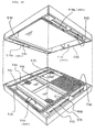
- FIG. 24 shows how the inner frame 405 arranged as described above is inserted into and fitted within the inner frame fitting portion 460 of the outer frame 406 arranged as described above. That is, the inner frame 405 is inserted into and placed on the partition wall 468 and the inner frame receiving stands 473, 474 in the inner frame fitting portion 460 formed by the receiving plate 467, the inner side walls 461, 461, the outer side walls 462, 463 and the like of the outer frame 406.
- FIG. 25 shows the inside frame 5 assembled within the outer frame 6.
- a sifter frame is assembled such that the region of the rough powder dropping port 469 is partitioned from the fine powder region (formed as the space between the sifter net 451 and the receiving plate 467) by the partition walls 458, 468 of the inner frame and the outer frame and the other three sides.
- the fine powder dropping ports 465, 465 on both sides are caused to communicate with the rough powder region through the slit-shaped fine powder dropping ports 475,but are partitioned from the rough powder dropping port 469 by the inner side wall 461, the lower inner side wall 476 and the brackets 477.
- FIG. 26 a plurality of the sifter frames each assembled as described above are stacked with the rough powder dropping ports 469 thereof successively disposed alternately to arrange a group of the sifter frames.
- An annular seal surface 480 (shown by cross-hatching in the figure) formed by applying the intimate contact sheet 458a on the lower surface of the sifter frame of the upper stage in FIG. 26 comes into contact with a closed annular seal surface 481 formed on the upper surface of the sifter frame of the lower stage (shown by cross-hatching in the figure), so that these seal surfaces are caused to firmly come into contact with each other by biass pressure from the upper and lower side of the group of the sifter frames.
- the rough powder dropping ports 469 of the rough powder regions which are partitioned from the other spaces by a plurality of the stacked sifter frames and directed generally vertically, are located at the alternate positions of the respective stages. Also, the space formed below the sifter net 451 and the receiving plate 467 of the upper stage sifter frame is partitioned and sealed from the fine powder dropping ports 465, 465 by the lower inner side walls 476, 476, whereby the continuous rough powder region which meanders horizontally from the upper side toward the lower side as a whole is formed.
- the fine powder dropping ports 465, 465 are formed as a port which is continued in a generally vertical direction by the stacked sifter frames and communicates with the space below the sifter net of the sifter frame of each stage through the slit-shaped fine powder dropping ports 475 as described above.
- the rough powder drops onto the sifter net 451 of the next stage from the rough powder dropping port 469 while moving on the sifter net 451, then moves on the sifter net 451 of the next stage to the rough powder dropping port 469 located on the opposite side in the same way and further drops onto the sifter net of the next stage. Then, the rough powder is discharged to the outside of the system through the lowermost sifter frame while meandering with the successive repetition of the above operation (refer to FIG. 17).
- fine powder having passed through the sifter nets 451 of the respective stages drops onto a receiving plate 467, then drops into the fine powder dropping ports 465, 465 from right and left slit-shaped fine powder dropping ports 475 and is introduced to a fine powder collection path.
- the seal surfaces for partitioning and sealing the rough powder region from the fine powder region are formed as the annular seal surfaces located on the same plane, portions on which a pressure applying force does not act, which is found in prior art, do not exist anywhere, so that an intimate contact seal can be securely realized and a possibility of the mixture of rough powder with fine powder in the fine powder region can be securely prevented.
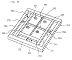
- the seventh embodiment shown in 27 - FIG. 31 is arranged substantially similarly to the sixth embodiment except that the seventh embodiment exemplifies an upper and lower frame type sifter frame for connecting an upper frame and a lower frame each substantially co-planar with the upper half portion of the fine powder dropping port of the sixth embodiment being accommodated in the inner frame.
- an upper frame 205 in FIG. 27 is composed of frame members 252 - 255 of, for example, wood square columns constituting a rectangular four-sided frame, a partition wall 258 for partitioning the inside of the rectangular four sides into a sifter net region 250 and a region for a rough powder dropping port 259.
- Reinforcing wood bars 256, 257 are disposed in the sifter net region 250 in a cross shape, a sifter net 251 is stretched over the upper surface of the sifter net portion 250, and outer frame members 2641, 2641 are disposed to the outside of the frame members 254 - 255.
- the outer frame members 2641, 2641 are spaced apart from the inner frame members 254, 255 to form fine powder dropping ports 2651, 2651.
- Numerals 2721, 2721 denote reinforcing intermediate brackets. Further, a crimp net is stretched below the sifter net 251 and a cleaner is interposed therebetween similarly to the first embodiment.
- the upper frame 205 of the embodiment has the feature that the frame members 252 - 255, 256, 257, 2641 and the like and the partition wall 258 are composed of square column members each having the same height with the upper and lower surfaces thereof flush.
- the partition wall 258 partitioning the sifter net region 250 from the region of the rough powder dropping port 259 is composed of a frame member having a large cross sectional area so that it has a large modulus of section.
- an intimate contact sheet 258a such as non-woven fabric, felt and the like (refer to FIG. 29) to the lower surface of the partition wall 258 (or to the upper surface of the partition wall 268 of the outer frame).
- An inclined surface may be formed to the partition wall 258 (refer to numeral 502a of FIG. 32) in the same way as prior art to enable rough powder to easily drop into the rough powder dropping port 258.
- FIG. 28 shows the lower frame 206 of the embodiment partitioned into a fine powder receiving region provided with a receiving plate 267 and a rough powder dropping port 269 by outer side walls 2642, 2642, a pair of outer side walls 262, 263 perpendicular to them and the partitioning wall 268 inwardly of the outer side walls 262, 263, with the inner side walls of the lower frame 206 omitted.
- the rough powder dropping port 269 and the partition wall 268 are arranged such that the positions and shapes thereof coincide with those of the rough powder dropping port 259 and the partition wall 258 of the upper frame 205.
- a pair of the parallel side walls 262, 263 are fixed to the outer side walls 2642 to form a rectangular four-sided frame having the same outside shape as that of the upper frame 205.
- Fine powder dropping ports 2652, 2652 are formed between each of the outer side walls 2642, 2642 and the receiving plate 267.
- numeral 266 denotes a reinforcing intermediate bracket for fixing the partition wall 268 to the outer side wall 262.
- the receiving plate 267 in the embodiment is formed from a rectangular stainless steel sheet fixed by screws. Further, lower inner side walls 276, 276 are disposed under the receiving plate 267 and constitute a vertical pair with the frame members 254, 255 of the upper frame. The lower surfaces of the lower inner side walls 276, 276 are flush with the lower surfaces of the outer side walls 262, 263, 2642 to press the upper frames 255, 254 stacked in the lower stage,
- the receiving plate 267 provides the space of a fine powder region for receiving fine powder (through) having passed through the sifter net 251 of the upper frame 205. As the sifter frame is vibrated, the fine powder is dropped into the fine powder dropping ports 2652.
- numeral 277 denotes brackets fixed to close the gaps between the inner side wall 261 and the lower inner side wall 276 at the both ends of the rough powder dropping port 269.
- the lower inner side walls 276 are disposed such that the seal surfaces 280 of intimate contact sheets 276a applied to the lower surfaces thereof are engaged with the frame member 254 (or 255) of the upper frame of the sifter frame stacked in the lower stage.
- FIG. 29 shows how the upper frame 205 arranged as described above is vertically connected to the lower frame 206 arranged as described above, and further FIG. 30 shows the frames assembled.
- the frame members 254, 255 of the upper frame are supported only by the intermediate members 2721, the division of the rough powder region from the fine powder region as an object of the present invention can be sufficiently achieved by the sufficient intimate contact effected by the brackets 277 and the partition wall 268.
- a sifter frame is assembled such that the regions of the rough powder dropping ports 259, 269 are partitioned from the fine powder region formed as the space between the sifter net 251 and the receiving plate 267, by the partition walls 258, 268 of the upper frame and the lower frame.
- the fire powder dropping ports 2651, 2652 on both sides are partitioned from the rough powder dropping ports 259, 269 by the frame members 254, 255 of the upper frame, the lower inner side walls 276 and the brackets 277.
- Seal surfaces 280 are formed by applying an intimate contact sheet on the lower surface of the sifter frame stacked to the upper stage in FIG. 31 (the seal surface 258a of the partition wall shown by cross-hatching in the figure) and the like come into contact with the seal surfaces formed on the upper surface of the sifter frame stacked to the lower surface, whereby these seal surfaces are pressed and sealed by a strong force applied from the upper and lower sides of a group of the sifter frames.
- the rough powder dropping ports 259, 269 of the rough powder region which are partitioned by a plurality of the stacked sifter frames from the other spaces and directed in a generally vertical direction are located at alternate positions of the respective stages.
- the space formed below the sifter net 251 and the receiving plate 267 of the upper stage sifter frame is partitioned from the fine powder dropping ports 2651, 2652 by the lower inner side walls 276, 276, whereby the continuous rough powder region which meanders horizontally from the upper side toward the lower side is formed as a whole.
- the fine powder dropping ports 2651, 2652 are formed as a port which is continued by the stacked sifter frames in a generally vertical direction and communicates with the space below the sifter net 251 through the gap between each of the frame members 254, 255 of the aforesaid upper frame and the receiving plate 267 with respect to the sifter frame of each stage.
- the paths of the fine powder can be widened to cope with fine powder difficult to flow.
- the rough powder drops onto the sifter net 251 of the next stage from the rough powder dropping ports 259, 269 while moving on the sifter net 251 in the same way as earlier embodiments then moves on the sifter net 251 of the next stage to the rough powder dropping ports 259, 269 located on the opposite side in the same way and further drops onto the sifter net of the next stage.
- the rough powder is discharged to the outside of the system through the lowermost sifter frame while meandering with the successive repetition of the above operation (refer to FIG. 17).
- fine powder having passed through the sifter nets 251 of the respective stages drops onto the receiving plate 267, then drops into the fine powder dropping ports 2651, 2652 from right and left slit-shaped fine powder dropping ports and is introduced to a fine powder collection path.
- the portion in which the sifter net is stretched can be prepared as a limited arrangement in the same way as prior art, there can be obtained an effect that a volume of sifter frames to be prepared for replacement can be reduced and labor for a replacement job can be saved. Further, mixing of rough powder with fine powder which may be caused by the conventional shifter frame can be substantially completely prevented.
Landscapes
- Engineering & Computer Science (AREA)
- Manufacturing & Machinery (AREA)
- Combined Means For Separation Of Solids (AREA)
Priority Applications (1)
| Application Number | Priority Date | Filing Date | Title |
|---|---|---|---|
| EP01115065A EP1145773A3 (de) | 1994-10-11 | 1994-11-11 | Siebkasten für Pulverteilchensieb |
Applications Claiming Priority (6)
| Application Number | Priority Date | Filing Date | Title |
|---|---|---|---|
| JP24550594A JPH08108140A (ja) | 1994-10-11 | 1994-10-11 | 粉粒体篩装置に用いる多段積層式用の篩枠 |
| JP245505/94 | 1994-10-11 | ||
| JP24550594 | 1994-10-11 | ||
| JP26579294A JP3479565B2 (ja) | 1994-10-28 | 1994-10-28 | 粉粒体篩装置に用いる多段積層式用の篩枠 |
| JP265792/94 | 1994-10-28 | ||
| JP26579294 | 1994-10-28 |
Related Child Applications (1)
| Application Number | Title | Priority Date | Filing Date |
|---|---|---|---|
| EP01115065A Division EP1145773A3 (de) | 1994-10-11 | 1994-11-11 | Siebkasten für Pulverteilchensieb |
Publications (2)
| Publication Number | Publication Date |
|---|---|
| EP0706836A1 true EP0706836A1 (de) | 1996-04-17 |
| EP0706836B1 EP0706836B1 (de) | 2002-02-06 |
Family
ID=26537265
Family Applications (2)
| Application Number | Title | Priority Date | Filing Date |
|---|---|---|---|
| EP01115065A Withdrawn EP1145773A3 (de) | 1994-10-11 | 1994-11-11 | Siebkasten für Pulverteilchensieb |
| EP94308333A Expired - Lifetime EP0706836B1 (de) | 1994-10-11 | 1994-11-11 | Siebkasten für Pulverteilchensieb |
Family Applications Before (1)
| Application Number | Title | Priority Date | Filing Date |
|---|---|---|---|
| EP01115065A Withdrawn EP1145773A3 (de) | 1994-10-11 | 1994-11-11 | Siebkasten für Pulverteilchensieb |
Country Status (3)
| Country | Link |
|---|---|
| US (2) | US5598931A (de) |
| EP (2) | EP1145773A3 (de) |
| DE (1) | DE69429809T2 (de) |
Cited By (5)
| Publication number | Priority date | Publication date | Assignee | Title |
|---|---|---|---|---|
| WO2015126335A1 (en) * | 2014-02-18 | 2015-08-27 | Sedat Kunduraci | A modular sieving box |
| CN110280470A (zh) * | 2019-05-22 | 2019-09-27 | 江苏谷泰粮食机械科技有限公司 | 一种清粮机用粮食分筛结构 |
| WO2019142145A3 (en) * | 2018-01-19 | 2019-10-31 | Ocrim S.P.A. | Interchangeable backwire/combined sieve and dynamic combined cleaner |
| CH720204A1 (de) * | 2022-11-07 | 2024-05-15 | Swisca Ag | Siebvorrichtung für Plansichter zum Fraktionieren von Getreidemahlprodukten |
| CH720205A1 (de) * | 2022-11-07 | 2024-05-15 | Swisca Ag | Siebvorrichtung für Plansichter zum Fraktionieren von Getreidemahlprodukten |
Families Citing this family (11)
| Publication number | Priority date | Publication date | Assignee | Title |
|---|---|---|---|---|
| TR199802567T2 (en) | 1996-08-20 | 1999-05-21 | Bhler Ag | D�z Kalbur Tertibat� |
| DE19706601C1 (de) * | 1997-02-20 | 1998-11-12 | Buehler Ag | Siebrahmen für Plansichter und Verfahren zu dessen Herstellung |
| US6439392B1 (en) * | 1997-09-02 | 2002-08-27 | Southwestern Wire Cloth, Inc. | Vibrating screen assembly with tubular frame |
| US6672460B2 (en) * | 1997-09-02 | 2004-01-06 | Southwestern Wire Cloth, Inc. | Vibrating screen assembly with integrated gasket and frame |
| US7210582B2 (en) * | 2004-05-05 | 2007-05-01 | M-I L.L.C. | Screen and screen frame for improved screen to shaker placement, handling and retention |
| GB2419308A (en) * | 2004-10-14 | 2006-04-26 | Satake Eng Co Ltd | Sieve frame with labyrinth seal |
| US20070108107A1 (en) * | 2005-11-15 | 2007-05-17 | Morrow Deborah E | Disposable pre-tensioned sieve frame and method of making same |
| DE102006005967A1 (de) * | 2006-02-08 | 2007-08-09 | Bühler AG | Sieb |
| USD571168S1 (en) * | 2007-08-16 | 2008-06-17 | Dean Sais | Archaeological equipment sifter |
| US8679328B2 (en) * | 2012-04-10 | 2014-03-25 | Frank Hebert | Floor drain cover |
| CN111842096A (zh) * | 2019-04-24 | 2020-10-30 | 布勒(无锡)商业有限公司 | 筛格及包括其的筛分设备 |
Citations (5)
| Publication number | Priority date | Publication date | Assignee | Title |
|---|---|---|---|---|
| US2181605A (en) * | 1936-10-21 | 1939-11-28 | William E Norvell | Separable sieve for bolters |
| FR892887A (fr) * | 1943-03-26 | 1944-05-23 | Appareil de tamisage | |
| GB705389A (en) * | 1950-03-06 | 1954-03-10 | Miag Vertriebs Gmbh | Improvements in or relating to screening frames |
| GB883054A (en) * | 1957-11-11 | 1961-11-22 | Simon Ltd Henry | Improvements in plansifters |
| DE2506981B1 (de) * | 1975-02-19 | 1976-06-10 | Nisshin Seifun K K | Siebkasten fuer eine etagensiebvorrichtung |
Family Cites Families (9)
| Publication number | Priority date | Publication date | Assignee | Title |
|---|---|---|---|---|
| US2068413A (en) * | 1934-11-26 | 1937-01-19 | Allan D Hunsicker | Sieve |
| DE892887C (de) * | 1943-10-29 | 1953-10-12 | Sack Gmbh Maschf | Blechrichtmaschine |
| US2455383A (en) * | 1947-09-16 | 1948-12-07 | Richmond Mfg Company | Screen for gyratory sifters, screens, or bolting equipment |
| US2576794A (en) * | 1948-07-19 | 1951-11-27 | William R Jost | Demountable tray sieve |
| AT169734B (de) * | 1950-08-18 | 1951-12-10 | Ernst Dipl Ing Fischer | Bürstvorrichtung für Getreidemahlprodukte |
| GB720437A (en) * | 1951-09-08 | 1954-12-22 | Miag Muehlenbau & Ind Gmbh | Improvements in or relating to slide frames for vibratory sieves |
| US3565251A (en) * | 1968-12-30 | 1971-02-23 | Blaw Knox Co | Plastic internal screen |
| DE4101710A1 (de) * | 1991-01-22 | 1992-07-23 | Hein Lehmann Trenn Foerder | Siebflaeche fuer eine siebmaschine |
| CH685604A5 (de) * | 1992-02-29 | 1995-08-31 | Buehler Ag | Plansichter. |
-
1994
- 1994-11-07 US US08/335,578 patent/US5598931A/en not_active Expired - Fee Related
- 1994-11-11 DE DE69429809T patent/DE69429809T2/de not_active Expired - Fee Related
- 1994-11-11 EP EP01115065A patent/EP1145773A3/de not_active Withdrawn
- 1994-11-11 EP EP94308333A patent/EP0706836B1/de not_active Expired - Lifetime
-
1996
- 1996-06-12 US US08/662,065 patent/US5664686A/en not_active Expired - Fee Related
Patent Citations (5)
| Publication number | Priority date | Publication date | Assignee | Title |
|---|---|---|---|---|
| US2181605A (en) * | 1936-10-21 | 1939-11-28 | William E Norvell | Separable sieve for bolters |
| FR892887A (fr) * | 1943-03-26 | 1944-05-23 | Appareil de tamisage | |
| GB705389A (en) * | 1950-03-06 | 1954-03-10 | Miag Vertriebs Gmbh | Improvements in or relating to screening frames |
| GB883054A (en) * | 1957-11-11 | 1961-11-22 | Simon Ltd Henry | Improvements in plansifters |
| DE2506981B1 (de) * | 1975-02-19 | 1976-06-10 | Nisshin Seifun K K | Siebkasten fuer eine etagensiebvorrichtung |
Cited By (11)
| Publication number | Priority date | Publication date | Assignee | Title |
|---|---|---|---|---|
| WO2015126335A1 (en) * | 2014-02-18 | 2015-08-27 | Sedat Kunduraci | A modular sieving box |
| CN106232245A (zh) * | 2014-02-18 | 2016-12-14 | 尤塞利斯机械工业贸易有限公司 | 模块化筛分盒 |
| US20170066018A1 (en) * | 2014-02-18 | 2017-03-09 | Yukselis Makina Sanayive Ticaret Anonim Sirketi | A modular sieving box |
| WO2019142145A3 (en) * | 2018-01-19 | 2019-10-31 | Ocrim S.P.A. | Interchangeable backwire/combined sieve and dynamic combined cleaner |
| US10730076B2 (en) | 2018-01-19 | 2020-08-04 | Ocrim S.P.A. | Interchangeable backwire/combined sieve and dynamic combined cleaner |
| US11351574B2 (en) | 2018-01-19 | 2022-06-07 | Ocrim S.P.A. | Interchangeable backwire/combined sieve and dynamic combined cleaner |
| CN110280470A (zh) * | 2019-05-22 | 2019-09-27 | 江苏谷泰粮食机械科技有限公司 | 一种清粮机用粮食分筛结构 |
| CH720204A1 (de) * | 2022-11-07 | 2024-05-15 | Swisca Ag | Siebvorrichtung für Plansichter zum Fraktionieren von Getreidemahlprodukten |
| CH720205A1 (de) * | 2022-11-07 | 2024-05-15 | Swisca Ag | Siebvorrichtung für Plansichter zum Fraktionieren von Getreidemahlprodukten |
| WO2024099977A1 (de) * | 2022-11-07 | 2024-05-16 | Swisca Ag | Siebvorrichtung für plansichter zum fraktionieren von getreidemahlprodukten |
| WO2024099976A1 (de) * | 2022-11-07 | 2024-05-16 | Swisca Ag | Siebvorrichtung für plansichter zum fraktionieren von getreidemahlprodukten |
Also Published As
| Publication number | Publication date |
|---|---|
| EP0706836B1 (de) | 2002-02-06 |
| US5598931A (en) | 1997-02-04 |
| DE69429809T2 (de) | 2002-09-12 |
| EP1145773A2 (de) | 2001-10-17 |
| DE69429809D1 (de) | 2002-03-21 |
| US5664686A (en) | 1997-09-09 |
| EP1145773A3 (de) | 2001-10-24 |
Similar Documents
| Publication | Publication Date | Title |
|---|---|---|
| EP0706836A1 (de) | Siebkasten für Pulverteilchensieb | |
| JP3316032B2 (ja) | 粉粒体篩機用の篩枠 | |
| US6202857B1 (en) | Frame for flat sifter and process for producing the same | |
| JP2931406B2 (ja) | プランシフターのための装置 | |
| US9884345B2 (en) | Method and apparatuses for screening | |
| EP1227896B1 (de) | Siebeinrichtung | |
| US11745206B2 (en) | Filtering apparatus with at least one filter unit | |
| CN210700579U (zh) | 一种能多级筛分的粉体研磨设备 | |
| EP0359878B1 (de) | Mehrfach-Filtersieb | |
| AU701165B2 (en) | Convertible kits for a material separating apparatus | |
| CN101616752A (zh) | 平筛及其驱动装置 | |
| JP3479565B2 (ja) | 粉粒体篩装置に用いる多段積層式用の篩枠 | |
| CN209791965U (zh) | 一种粉末震动筛 | |
| CN214610015U (zh) | 一种具有装配功能的振动盘 | |
| CN214682864U (zh) | 一种改良型振筛 | |
| CN223683942U (zh) | 一种面包加工用筛粉机 | |
| JP2001300426A (ja) | 篩枠ユニットを多段積層した粉粒体篩装置 | |
| JPH08108140A (ja) | 粉粒体篩装置に用いる多段積層式用の篩枠 | |
| AU2007214235B2 (en) | Sieve | |
| CN115625111A (zh) | 振动散料筛分设备、振动散料分拣系统及物料筛选分拣方法 | |
| CN120152792A (zh) | 用于对谷物研磨产品进行分级的平筛的筛分装置 | |
| GB2276572A (en) | Screen frame assembly with frame-bonded screen cloth and removable ball tray | |
| CN220215715U (zh) | 一种圆盘筛 | |
| CN220215702U (zh) | 粉机多层分级筛网装置 | |
| CN214917997U (zh) | 一种振动筛砂旋转倾倒装置 |
Legal Events
| Date | Code | Title | Description |
|---|---|---|---|
| PUAI | Public reference made under article 153(3) epc to a published international application that has entered the european phase |
Free format text: ORIGINAL CODE: 0009012 |
|
| AK | Designated contracting states |
Kind code of ref document: A1 Designated state(s): CH DE GB LI |
|
| 17P | Request for examination filed |
Effective date: 19960723 |
|
| 17Q | First examination report despatched |
Effective date: 19981120 |
|
| GRAG | Despatch of communication of intention to grant |
Free format text: ORIGINAL CODE: EPIDOS AGRA |
|
| GRAG | Despatch of communication of intention to grant |
Free format text: ORIGINAL CODE: EPIDOS AGRA |
|
| GRAH | Despatch of communication of intention to grant a patent |
Free format text: ORIGINAL CODE: EPIDOS IGRA |
|
| GRAH | Despatch of communication of intention to grant a patent |
Free format text: ORIGINAL CODE: EPIDOS IGRA |
|
| GRAA | (expected) grant |
Free format text: ORIGINAL CODE: 0009210 |
|
| REG | Reference to a national code |
Ref country code: GB Ref legal event code: IF02 |
|
| RAP1 | Party data changed (applicant data changed or rights of an application transferred) |
Owner name: NISSHIN SEIFUN GROUP INC. |
|
| AK | Designated contracting states |
Kind code of ref document: B1 Designated state(s): CH DE GB LI |
|
| REG | Reference to a national code |
Ref country code: CH Ref legal event code: EP |
|
| RAP2 | Party data changed (patent owner data changed or rights of a patent transferred) |
Owner name: NISSHIN FLOUR MILLING INC. |
|
| REF | Corresponds to: |
Ref document number: 69429809 Country of ref document: DE Date of ref document: 20020321 |
|
| REG | Reference to a national code |
Ref country code: CH Ref legal event code: NV Representative=s name: BOVARD AG PATENTANWAELTE |
|
| PLBE | No opposition filed within time limit |
Free format text: ORIGINAL CODE: 0009261 |
|
| STAA | Information on the status of an ep patent application or granted ep patent |
Free format text: STATUS: NO OPPOSITION FILED WITHIN TIME LIMIT |
|
| 26N | No opposition filed |
Effective date: 20021107 |
|
| PGFP | Annual fee paid to national office [announced via postgrant information from national office to epo] |
Ref country code: DE Payment date: 20051103 Year of fee payment: 12 |
|
| PGFP | Annual fee paid to national office [announced via postgrant information from national office to epo] |
Ref country code: GB Payment date: 20051109 Year of fee payment: 12 |
|
| PGFP | Annual fee paid to national office [announced via postgrant information from national office to epo] |
Ref country code: CH Payment date: 20051115 Year of fee payment: 12 |
|
| PG25 | Lapsed in a contracting state [announced via postgrant information from national office to epo] |
Ref country code: LI Free format text: LAPSE BECAUSE OF NON-PAYMENT OF DUE FEES Effective date: 20061130 Ref country code: CH Free format text: LAPSE BECAUSE OF NON-PAYMENT OF DUE FEES Effective date: 20061130 |
|
| PG25 | Lapsed in a contracting state [announced via postgrant information from national office to epo] |
Ref country code: DE Free format text: LAPSE BECAUSE OF NON-PAYMENT OF DUE FEES Effective date: 20070601 |
|
| REG | Reference to a national code |
Ref country code: CH Ref legal event code: PL |
|
| GBPC | Gb: european patent ceased through non-payment of renewal fee |
Effective date: 20061111 |
|
| PG25 | Lapsed in a contracting state [announced via postgrant information from national office to epo] |
Ref country code: GB Free format text: LAPSE BECAUSE OF NON-PAYMENT OF DUE FEES Effective date: 20061111 |