EP1145791B1 - Fliegende schere mit zylindrischem drehkörper - Google Patents
Fliegende schere mit zylindrischem drehkörper Download PDFInfo
- Publication number
- EP1145791B1 EP1145791B1 EP99923901A EP99923901A EP1145791B1 EP 1145791 B1 EP1145791 B1 EP 1145791B1 EP 99923901 A EP99923901 A EP 99923901A EP 99923901 A EP99923901 A EP 99923901A EP 1145791 B1 EP1145791 B1 EP 1145791B1
- Authority
- EP
- European Patent Office
- Prior art keywords
- rotating
- pair
- drum
- gears
- rotating drum
- Prior art date
- Legal status (The legal status is an assumption and is not a legal conclusion. Google has not performed a legal analysis and makes no representation as to the accuracy of the status listed.)
- Expired - Lifetime
Links
- 230000008878 coupling Effects 0.000 claims abstract description 51
- 238000010168 coupling process Methods 0.000 claims abstract description 51
- 238000005859 coupling reaction Methods 0.000 claims abstract description 51
- 238000010008 shearing Methods 0.000 claims description 12
- 238000013459 approach Methods 0.000 claims description 11
- 230000002093 peripheral effect Effects 0.000 claims description 4
- 230000005540 biological transmission Effects 0.000 description 39
- 238000012423 maintenance Methods 0.000 description 6
- 238000005098 hot rolling Methods 0.000 description 3
- 238000005096 rolling process Methods 0.000 description 3
- 238000004519 manufacturing process Methods 0.000 description 2
- 238000006073 displacement reaction Methods 0.000 description 1
Images


Classifications
-
- B—PERFORMING OPERATIONS; TRANSPORTING
- B26—HAND CUTTING TOOLS; CUTTING; SEVERING
- B26D—CUTTING; DETAILS COMMON TO MACHINES FOR PERFORATING, PUNCHING, CUTTING-OUT, STAMPING-OUT OR SEVERING
- B26D7/00—Details of apparatus for cutting, cutting-out, stamping-out, punching, perforating, or severing by means other than cutting
- B26D7/26—Means for mounting or adjusting the cutting member; Means for adjusting the stroke of the cutting member
- B26D7/2628—Means for adjusting the position of the cutting member
- B26D7/265—Journals, bearings or supports for positioning rollers or cylinders relatively to each other
-
- B—PERFORMING OPERATIONS; TRANSPORTING
- B23—MACHINE TOOLS; METAL-WORKING NOT OTHERWISE PROVIDED FOR
- B23D—PLANING; SLOTTING; SHEARING; BROACHING; SAWING; FILING; SCRAPING; LIKE OPERATIONS FOR WORKING METAL BY REMOVING MATERIAL, NOT OTHERWISE PROVIDED FOR
- B23D25/00—Machines or arrangements for shearing stock while the latter is travelling otherwise than in the direction of the cut
- B23D25/12—Shearing machines with blades on coacting rotating drums
-
- B—PERFORMING OPERATIONS; TRANSPORTING
- B23—MACHINE TOOLS; METAL-WORKING NOT OTHERWISE PROVIDED FOR
- B23D—PLANING; SLOTTING; SHEARING; BROACHING; SAWING; FILING; SCRAPING; LIKE OPERATIONS FOR WORKING METAL BY REMOVING MATERIAL, NOT OTHERWISE PROVIDED FOR
- B23D35/00—Tools for shearing machines or shearing devices; Holders or chucks for shearing tools
- B23D35/005—Adjusting the position of the cutting members
-
- B—PERFORMING OPERATIONS; TRANSPORTING
- B26—HAND CUTTING TOOLS; CUTTING; SEVERING
- B26D—CUTTING; DETAILS COMMON TO MACHINES FOR PERFORATING, PUNCHING, CUTTING-OUT, STAMPING-OUT OR SEVERING
- B26D1/00—Cutting through work characterised by the nature or movement of the cutting member or particular materials not otherwise provided for; Apparatus or machines therefor; Cutting members therefor
- B26D1/56—Cutting through work characterised by the nature or movement of the cutting member or particular materials not otherwise provided for; Apparatus or machines therefor; Cutting members therefor involving a cutting member which travels with the work otherwise than in the direction of the cut, i.e. flying cutter
- B26D1/62—Cutting through work characterised by the nature or movement of the cutting member or particular materials not otherwise provided for; Apparatus or machines therefor; Cutting members therefor involving a cutting member which travels with the work otherwise than in the direction of the cut, i.e. flying cutter and is rotating about an axis parallel to the line of cut, e.g. mounted on a rotary cylinder
- B26D1/626—Cutting through work characterised by the nature or movement of the cutting member or particular materials not otherwise provided for; Apparatus or machines therefor; Cutting members therefor involving a cutting member which travels with the work otherwise than in the direction of the cut, i.e. flying cutter and is rotating about an axis parallel to the line of cut, e.g. mounted on a rotary cylinder for thin material, e.g. for sheets, strips or the like
-
- B—PERFORMING OPERATIONS; TRANSPORTING
- B26—HAND CUTTING TOOLS; CUTTING; SEVERING
- B26D—CUTTING; DETAILS COMMON TO MACHINES FOR PERFORATING, PUNCHING, CUTTING-OUT, STAMPING-OUT OR SEVERING
- B26D5/00—Arrangements for operating and controlling machines or devices for cutting, cutting-out, stamping-out, punching, perforating, or severing by means other than cutting
- B26D5/02—Means for moving the cutting member into its operative position for cutting
-
- B—PERFORMING OPERATIONS; TRANSPORTING
- B26—HAND CUTTING TOOLS; CUTTING; SEVERING
- B26D—CUTTING; DETAILS COMMON TO MACHINES FOR PERFORATING, PUNCHING, CUTTING-OUT, STAMPING-OUT OR SEVERING
- B26D7/00—Details of apparatus for cutting, cutting-out, stamping-out, punching, perforating, or severing by means other than cutting
- B26D7/26—Means for mounting or adjusting the cutting member; Means for adjusting the stroke of the cutting member
- B26D7/2628—Means for adjusting the position of the cutting member
-
- Y—GENERAL TAGGING OF NEW TECHNOLOGICAL DEVELOPMENTS; GENERAL TAGGING OF CROSS-SECTIONAL TECHNOLOGIES SPANNING OVER SEVERAL SECTIONS OF THE IPC; TECHNICAL SUBJECTS COVERED BY FORMER USPC CROSS-REFERENCE ART COLLECTIONS [XRACs] AND DIGESTS
- Y10—TECHNICAL SUBJECTS COVERED BY FORMER USPC
- Y10T—TECHNICAL SUBJECTS COVERED BY FORMER US CLASSIFICATION
- Y10T83/00—Cutting
- Y10T83/465—Cutting motion of tool has component in direction of moving work
- Y10T83/4766—Orbital motion of cutting blade
- Y10T83/4795—Rotary tool
- Y10T83/483—With cooperating rotary cutter or backup
- Y10T83/4833—Cooperating tool axes adjustable relative to each other
-
- Y—GENERAL TAGGING OF NEW TECHNOLOGICAL DEVELOPMENTS; GENERAL TAGGING OF CROSS-SECTIONAL TECHNOLOGIES SPANNING OVER SEVERAL SECTIONS OF THE IPC; TECHNICAL SUBJECTS COVERED BY FORMER USPC CROSS-REFERENCE ART COLLECTIONS [XRACs] AND DIGESTS
- Y10—TECHNICAL SUBJECTS COVERED BY FORMER USPC
- Y10T—TECHNICAL SUBJECTS COVERED BY FORMER US CLASSIFICATION
- Y10T83/00—Cutting
- Y10T83/768—Rotatable disc tool pair or tool and carrier
- Y10T83/7809—Tool pair comprises rotatable tools
- Y10T83/783—Tool pair comprises contacting overlapped discs
- Y10T83/7834—With means to effect axial pressure on pair
- Y10T83/7838—With means to change axial pressure
-
- Y—GENERAL TAGGING OF NEW TECHNOLOGICAL DEVELOPMENTS; GENERAL TAGGING OF CROSS-SECTIONAL TECHNOLOGIES SPANNING OVER SEVERAL SECTIONS OF THE IPC; TECHNICAL SUBJECTS COVERED BY FORMER USPC CROSS-REFERENCE ART COLLECTIONS [XRACs] AND DIGESTS
- Y10—TECHNICAL SUBJECTS COVERED BY FORMER USPC
- Y10T—TECHNICAL SUBJECTS COVERED BY FORMER US CLASSIFICATION
- Y10T83/00—Cutting
- Y10T83/929—Tool or tool with support
- Y10T83/9457—Joint or connection
-
- Y—GENERAL TAGGING OF NEW TECHNOLOGICAL DEVELOPMENTS; GENERAL TAGGING OF CROSS-SECTIONAL TECHNOLOGIES SPANNING OVER SEVERAL SECTIONS OF THE IPC; TECHNICAL SUBJECTS COVERED BY FORMER USPC CROSS-REFERENCE ART COLLECTIONS [XRACs] AND DIGESTS
- Y10—TECHNICAL SUBJECTS COVERED BY FORMER USPC
- Y10T—TECHNICAL SUBJECTS COVERED BY FORMER US CLASSIFICATION
- Y10T83/00—Cutting
- Y10T83/929—Tool or tool with support
- Y10T83/9457—Joint or connection
- Y10T83/9464—For rotary tool
- Y10T83/9469—Adjustable
-
- Y—GENERAL TAGGING OF NEW TECHNOLOGICAL DEVELOPMENTS; GENERAL TAGGING OF CROSS-SECTIONAL TECHNOLOGIES SPANNING OVER SEVERAL SECTIONS OF THE IPC; TECHNICAL SUBJECTS COVERED BY FORMER USPC CROSS-REFERENCE ART COLLECTIONS [XRACs] AND DIGESTS
- Y10—TECHNICAL SUBJECTS COVERED BY FORMER USPC
- Y10T—TECHNICAL SUBJECTS COVERED BY FORMER US CLASSIFICATION
- Y10T83/00—Cutting
- Y10T83/929—Tool or tool with support
- Y10T83/9457—Joint or connection
- Y10T83/9464—For rotary tool
- Y10T83/9469—Adjustable
- Y10T83/9471—Rectilinearly
Definitions
- This invention relates to a rotating-drum flying shear applied to a hot rolling equipment line or the like.
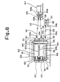
- FIG. 8 shows the outline of a conventional rotating-drum flying shear disclosed in this publication.
- an extractable bearing frame 102 is mounted inside a housing 101. Inside the bearing frame 102, an upper rotating drum 103 and a lower rotating drum 104 as a pair are supported rotatably and movably toward and away from each other.
- the rotating drums 103 and 104 have shearing blades 103a and 104a, respectively, on their outer peripheral portions along their axial direction. That is, the upper rotating drum 103 has shaft end portions supported by the bearing frame 102 via eccentric sleeves 105, while the lower rotating drum 104 has shaft end portions supported by the bearing frame 102 via eccentric sleeves 106.
- the eccentric sleeves 105 and 106 By turning the eccentric sleeves 105 and 106, the upper and lower rotating drums 103 and 104 can be moved up and down so as to be movable toward and away from each other.
- a drive motor 107 is installed Laterally of the housing 101.
- An output shaft of the drive motor 107 is coupled to a gear box 108 having a pair of timing gears 108a, 108b.
- a rotating shaft of the timing gear 108a is connected to the shaft end portion of the upper rotating drum 103 by a transmission shaft 110 having universal joints 109a, 109b.
- a rotating shaft of the timing gear 108b is connected to the shaft end portion of the lower rotating drum 104 by a transmission shaft 112 having universal joints 111a, 111b.
- a coupling gear 113 is fixed to the outside of the eccentric sleeve 105 that supports each shaft end portion of the upper rotating drum 103.
- a coupling gear 114 meshing with the coupling gear 113 is fixed to the outside of the eccentric sleeve 106 that supports each shaft end portion of the lower rotating drum 104.
- a coupling gear 115 meshing with the coupling gear 114 is rotatably supported on the bearing frame 102 by a connecting shaft 116.
- a drive motor 117 is installed.
- An output shaft 118 of the drive motor 117 is connected to the connecting shaft 116 via a transmission shaft 120 having universal joints 119a, 119b.
- an interlocking gear 121 is fixed to each shaft end portion of the upper rotating drum 103 externally of the coupling gear 113.
- an interlocking gear 122 is fixed externally of the coupling gear 114.
- the interlocking gear 121 and the interlocking gear 122 do not mesh when the upper rotating drum 103 and the lower rotating drum 104 are apart from each other.
- the interlocking gear 121 and the interlocking gear 122 mesh.
- these rotating drums 103 and 104 can be instantaneously put into coaction with strong mesh.
- a strip plate (not shown) moves fast, while being rolled, on a rolling equipment line.
- The'strip plate passes between the upper rotating drum 103 and the lower rotating drum 104 that are separated from each other. Then, the strip plate is wound on a down-coiler at the end of the line.
- the drive motor 107 is driven to start rotating the rotating drums 103 and 104 synchronously in opposite directions via the transmission shafts 110 and 112, and adjust their rotational speed to be commensurate with the traveling speed of the strip plate.
- the drive motor 117 is driven to turn the eccentric sleeves 105, 106 via the transmission shaft 120 and the coupling gears 115, 113, 114, thereby making the rotating drums 103 and 104 approach each other.
- the interlocking gears 121 and 122 mesh, whereupon the rotating drums 103 and 104 coact with instantaneous strong mesh. Consequently, the strip plate during movement can be sheared by the shearing blades 103a and 104a.
- the conventional rotating-drum flying shear allows the single drive motor 107 to rotate the two rotating drums 103 and 104.
- the output shaft of the drive motor 107 is coupled to the gear box 108 having the timing gears 108a, 108b, and the gear boy 108 is connected to the shaft end portions of the rotating drums 103 and 104 by the two transmission shafts 110 und 112.
- the two transmission shafts 110 and 112 are disposed at upper and lower positions in the same vertical plans. This makes it difficult to support these transmission shafts 110 and 112, and complicates the arrangement of a transmission system, so that its maintenance is not easy.
- An embodiment of a rotating-drum flying shear comprises: a bearing frame; a pair of rotating drums each having shaft end portions rotatably supported by the bearing frame, and each having a shearing blade on an outer peripheral portion of the drum along an axial direction of the drum; rotating drum drive means for rotationally driving one of the pair of rotating drums; a pair of eccentric sleeves interposed, rotatably relative to each other, between the bearing frame and the shaft end portions of the pair of rotating drums; eccentric sleeve drive means for rotating the pair of eccentric sleeves relative to each other, thereby making the pair of rotating drums approach or separate from each other; rotating drum interlocking means for interlocking the pair of rotating drums when the pair of rotating drums approach each other; and rotating drum synchronizing means for synchronously rotating the one rotating drum and the other rotating drum regardless of approaching positions or separating positions of the pair of rotating drums.
- a single transmission system connects the rotating drum drive means and the rotating drums together, so that this transmission system can be downsized. Besides, it is easy to support this transmission system, and its arrangement can be simplified. Consequently, its maintenance can be performed with safety and ease.
- the rotating drum interlocking means has a pair of interlocking gears fixed to the shaft end portions of the pair of rotating drums
- the rotating drum synchronizing means has a pair of timing gears opposed to the pair of interlocking gears in an axial direction in a mutually meshing state and rotatably supported by the bearing frame, and Oldham' s couplings interposed between the pair of interlocking gears and the pair of timing gears.
- the interlocking gears, the timing gears, and the Oldham' s couplings are disposed, as a unit, on the bearing frame.
- the bearing frame can be extracted as a block together with these members, and checked and repaired as a unit.
- maintenance can be performed safely and easily.
- the pair of timing gears are disposed at positions opposed to the pair of interlocking gears when the pair of rotating drums are at separating positions, and the Oldham's couplings are disposed between end faces of the pair of interlocking gears and end faces of the pair of timing gears.
- the structure can be simplified, and the manufacturing cost can be reduced.
- the rotating drum interlocking means has a pair of interlocking gears fixed to the shaft end portions of the pair of rotating drums, and the rotating drum synchronizing means has a pair of timing gears rotatably and horizontally movably supported by the bearing frame, while meshing with each other and meshing with the pair of interlocking gears.
- the interlocking gears and the timing gears are disposed, as a unit, on the bearing frame.
- the bearing frame can be extracted as a block together with these members, and checked and repaired as a unit.
- maintenance can be performed safely and easily.
- the pair of timing gears are rotatably supported by a horizontally movable frame horizontally movably supported by the bearing frame, and the pair of timing gears are link coupled while meshing with the pair of interlocking gears.
- the structure can be simplified, and the manufacturing cost can be reduced.
- right and left extractable bearing frames 12 as a pair are mounted inside a housing 11.
- the right and left bearing frames 12 are composed as an integral block with the use of tie bolts (not shown).
- Inside the bearing frames 12, an upper rotating drum 13 and a lower rotating drum 14 as a pair are supported so as to be rotatable and upwardly and downwardly movable toward and away from each other.
- the rotating drums 13 and 14 have shearing blades 13a and 14a, respectively, on their outer peripheral portions along their axial direction. That is, the upper rotating drum 13 has shaft end portions supported by the bearing frames 12 via eccentric sleeves 15, while the lower rotating drum 14 has shaft end portions supported by the bearing frames 12 via eccentric sleeves 16.
- the eccentric sleeves 15 and 16 By turning the eccentric sleeves 15 and 16, the upper and lower rotating drums 13 and 14 can be moved up and down so as to be movable toward and away from each other.
- a drive motor 17 as a rotating drum drive means is installed laterally of the housing 11.
- An output shaft 18 of the drive motor 17 is connected to the shaft end portion of the upper rotating drum 13 by a transmission shaft 20 having universal joints 19a, 19b.
- the drive motor 17 is driven, its driving force is transmitted from the output shaft 18 to the upper rotating drum 13 via the transmission shaft 20.
- the upper rotating drum 13 can be rotated in one direction.
- a coupling gear 21 is fixed to the outside of the eccentric sleeve 15 that supports each shaft end portion of the upper rotating drum 13.
- a coupling gear 22 meshing with the coupling gear 21 is fixed to the outside of the eccentric sleeve 16 that supports each shaft end portion of the lower rotating drum 14.
- a coupling gear 23 meshing with the coupling gear 22 is rotatably supported on the bearing frame 12 by a connecting shaft 24.
- a drive motor 25 as an eccentric sleeve drive means is installed.
- An output shaft 26 of the drive motor 25 is connected to the connecting shaft 24 by a transmission shaft 28 having universal joints 27a, 27b.
- an interlocking gear 29 is fixed to each shaft end portion of the upper rotating drum 13 externally of the coupling gear 21.
- an interlocking gear 30 is fixed externally of the coupling gear 22. That is, the interlocking gears 29 and 30 constitute a rotating drum interlocking means .
- the interlocking gears 29 and 30 constitute a rotating drum interlocking means .
- a rotating drum synchronizing mechanism 31 is provided for transmitting the rotational force of the upper rotating drum 13 to the lower rotating drum 14 regardless of an approaching position or separating position of the upper rotating drum 13 to rotate both rotating drums 13 and 14 synchronously. That is, in the rotating drum synchronizing mechanism 31, upper and lower timing gears 33 and 34 as a pair are opposed, in a mutually meshing state, to the upper and lower interlocking gears 29 and 30 fixed to the shaft end portions of the rotating drums 13 and 14. Rotating shafts 33a and 34a of the timing gears 33 and 34 are rotatably supported by bearings 35 and 36 on a support frame 32 fixed to a frame housing 12a of the bearing frame 11. Between the upper and lower interlocking gears 29, 30 and the upper and lower timing gears 33, 34, Oldham's couplings 41, 42 are interposed, and these gears and couplings are connected together integrally rotatably.
- the Oldham's coupling 41 has an annular plate-like fitting piece 43 disposed between the interlocking gear 29 and the timing gear 33, as shown in detail in FIG. 3.
- right and left fitting grooves 44 as a pair are formed along a diametrical direction.
- upper and lower fitting grooves 45 as a pair are formed along a diametrical direction.
- right and left protrusions 46 as a pair to be fitted into the fitting grooves 44 are formed on an end face of the timing gear 33.
- upper and lower protrusions 47 as a pair to be fitted into the fitting grooves 45 are formed.
- the Oldham' s coupling 42 has the same constitution as that of the Oldham's coupling 41, and has a fitting piece 48 of the same shape as the fitting piece 43 disposed between the interlocking gear 30 and the timing gear 34.
- a strip plate moves fast, while being rolled, on a rolling equipment line. As shown in FIG. 1, the strip plate passes between the upper rotating drum 13 and the lower rotating drum 14 that are apart from each other. Then, the strip plate is wound on a down-coiler at the end of the line.
- the drive motor 17 is driven to rotate the upper rotating drum 13 via the transmission shaft 20, and also rotate the lower rotating drum 14 via the interlocking gear 29, the Oldham's coupling 41, the timing gears 33, 34, the Oldham' s coupling 42, and the interlocking gear 30.
- the upper rotating drum 13 and the lower rotating drum 14 are made to start rotation synchronously in opposite directions, and their rotational speed is adjusted to be commensurate with the traveling speed of the strip plate.
- the drive motor 25 is driven to turn the eccentric sleeves 15, 16 via the transmission shaft 28 and the coupling gears 23, 22, 21, thereby making the rotating drums 13 and 14 approach each other.
- the interlocking gears 29 and 30 mesh, whereupon the rotating drums 13 and 14 coact with instantaneous strong mesh. Consequently, the strip plate during movement can be sheared by the shearing blades 13a and 14a.
- the drive motor 17 is drivingly connected to the upper rotating drum 13 alone .
- the upper rotating drum 13 and the lower rotating drum are drivingly connected together at the work side by the rotating drum synchronizing mechanism 31 in which the interlocking gears 29, 30 and the timing gears 33, 34 are connected by the Oldham's couplings 41, 42 so that power can be constantly transmitted between them.
- the single transmission shaft 20 suffices to connect the drive motor 17 to the rotating drums 13, 14.
- the length of the transmission shaft 20 can be shortened by selecting the position of mounting of the drive motor 17 that minimizes the runout angle of the transmission shaft 20 during driving. Consequently, the drive system including the drive motor 17 and the transmission shaft 20 can be downsized.
- the timing gears 33, 34 are disposed inside the frame housing 12a of the bearing frame 12.
- the bearing frame 12 is extracted as a block, and can be checked and repaired along with the instruments on the drive side. Furthermore, support for the single transmission shaft 20 becomes easy, and the arrangement of the transmission system is simplified, so that its maintenance can be done safely and easily.
- An output shaft 18 of a drive motor 17 is connected to a shaft end portion of the upper rotating drum 13 by a transmission shaft 20 having universal joints 19a, 19b.
- coupling gears 21, 22 meshing with each other are fixed.
- the coupling gear 22 is in mesh with a coupling gear 24 supported on the bearing frame 12 by a connecting shaft 24.
- An output shaft 26 of a drive motor 25 is connected to the connecting shaft 24 by a transmission shaft 28 having universal joints 27a, 27b.
- interlocking gears 29, 30 are fixed which are situated outside the coupling gears 21, 22 and which can be in mesh or out of mesh with each other.
- a rotating drum synchronizing mechanism 51 is provided for transmitting the rotational force of the upper rotating drum 13 to the lower rotating drum 14 regardless of an approaching position or separating position of the upper rotating drum 13 to rotate both rotating drums 13 and 14 synchronously. That is, in the rotating drum synchronizing mechanism 51, a horizontally movable frame 52 is disposed inside a frame housing 12a of the bearing frame 12. A slide shoe 53 fixed to a lower portion of the horizontally movable frame 52 is supported by a rail piece 54, which is fixed to a bottom portion of the frame housing 12a, in such a manner as to be movable along a horizontal direction perpendicular to the axial direction of the rotating drums 13, 14. A projection 55 on an upper portion of the horizontally movable frame 52 is movably fitted into a guide groove 56 formed in a ceiling portion of the frame housing 12a.
- an upper timing gear 57 and a lower timing gear 58 as a pair are rotatably supported by rotating shafts 57a, 58a in a mutually meshing state.
- the upper and lower timing gears 57, 58 mesh with the upper and lower interlocking gears 29 and 30 fixed to the shaft end portions of the rotating drums 13 and 14.
- a pair of links 59, 60 are provided to span between the shaft end portions 13a, 14a of the rotating drums 13, 14 and the rotating shafts 57a, 58a.
- the rotational force of the upper rotating drum 13 is transmitted from the interlocking gear 29 to the timing gear 57, and then transmitted from the timing gear 58 meshing with the timing gear 57 to the interlocking gear 30.
- the lower rotating drum 14 integral with the interlocking gear 30 is rotated.
- the upper rotating drum 13 and the lower rotating drum 14 can be synchronously rotated in opposite directions.
- a strip plate moves fast, while being rolled, on a rolling equipment line. As shown in FIG. 4, the strip plate passes between the upper rotating drum 13 and the lower rotating drum 14 that are apart from each other. Then, the strip plate is wound on a down-coiler at the end of the line.
- the drive motor 17 is driven to rotate the upper rotating drum 13 via the transmission shaft 20, and also rotate the lower rotating drum 14 via the interlocking gear 29, the timing gears 57, 58, and the interlocking gear 30.
- the upper rotating drum 13 and the lower rotating drum 14 are made to start rotation synchronously in opposite directions, and their rotational speed is adjusted to be commensurate with the traveling speed of the strip plate.
- the drive motor 25 is driven to turn the eccentric sleeves 15, 16 via the transmission shaft 28 and the coupling gears 23, 22, 21, thereby making the rotating drums 13 and 14 approach each other.
- the interlocking gears 29 and 30 mesh, whereupon the rotating drums 13 and 14 coact with instantaneous strong mesh. Consequently, the strip plate during movement can be sheared by the shearing blades 13a and 14a.
- the drive motor 17 is drivingly connected to the upper rotating drum 13 alone.
- the upper rotating drum 13 and the lower rotating drum are drivingly connected together at the work side by the rotating drum synchronizing mechanism 51 in which the timing gears 57, 58 mounted on the horizontally movable frame 52 are connected to the interlocking gears 29, 30 for constant meshing therewith.
- the single transmission shaft 20 suffices to connect the drive motor 17 to the rotating drums 13, 14.
- the length of the transmission shaft 20 can be shortened by selecting the position of mounting of the drive motor 17 that minimizes the runout angle of the transmission shaft 20 during driving. Consequently, the drive system including the drive motor 17 and the transmission shaft 20 can be downsized.
- the timing gears 57, 58 are disposed inside the frame housing 12a of the bearing frame 12.
- the bearing frame 12 is extracted as a block, and can be checked and repaired along with the instruments on the drive side. Furthermore, support for the single transmission shaft 20 becomes easy, and the arrangement of a transmission system is simplified, so that its maintenance can be done safely and easily.
- the rotating-drum flying shear of the present invention has a rotating drum synchronizing means for synchronously rotating a pair of rotating drums having shearing blades, thereby downsizing and simplifying a driving force transmission system.
- This apparatus of the invention is preferred for use on a hot rolling equipment line or the like.
Landscapes
- Engineering & Computer Science (AREA)
- Mechanical Engineering (AREA)
- Life Sciences & Earth Sciences (AREA)
- Forests & Forestry (AREA)
- Shearing Machines (AREA)
- Crushing And Grinding (AREA)
- Transmission Devices (AREA)
Claims (5)
- Fliegende Schere mit zylindrischem Drehkörper, enthaltend: einen Lagerrahmen (12); zwei zylindrische Drehkörper (13, 14), die jeweils Wellenendabschnitte haben, die drehbar durch den Lagerrahmen (12) gehalten sind, und an denen jeweils eine Scherklinge (13a, 14a) an einem Außenumfang des zylindrischen Drehkörpers (13, 14) in Achsrichtung des zylindrischen Drehkörpers (13, 14) angebracht ist; eine Zylinderdrehkörper-Antriebseinrichtung (17) zum Drehen einer der beiden zylindrischen Drehkörper; zwei Exzenterbuchsen (15, 16), die relativ zueinander drehbar zwischen dem Lagerrahmen (12) und den Wellenendabschnitten der beiden zylindrischen Drehkörper (13, 14) angebracht sind; eine Exzenterbuchsen-Antriebseinrichtung (25) zum Drehen der beiden Exzenterbuchsen (15, 16) relativ zueinander, wodurch sich die beiden zylindrischen Drehkörper (13, 14) einander annähern oder voneinander entfernen; eine Zylinderdrehkörper-Verriegelungseinrichtung zum Verriegeln der beiden zylindrischen Drehkörper (13, 14) durch Ineinandergreifen von Steuerzahnrädern (29, 30), die jeweils am Wellenendabschnitt des zylindrischen Drehkörpers (13, 14) angebracht sind, wenn sich die beiden zylindrischen Drehkörper (13, 14) einander annähern; und eine Zylinderdrehkörper-Synchronisiereinrichtung (31) zum synchronen Drehen des einen zylindrischen Drehkörpers (13, 14) und des anderen zylindrischen Drehkörpers (13, 14) unabhängig von den Annäherungspositionen oder den Entfernungspositionen der beiden zylindrischen Drehkörper (13, 14), wobei die fliegende Schere mit zylindrischem Drehkörper dadurch gekennzeichnet ist, daß die Zylinderdrehkörper-Antriebseinrichtung (17) am einen Ende einer Welle der beiden zylindrischen Drehkörper (13, 14) angebracht ist und die Zylinderdrehkörper-Synchronisiereinrichtung (31) über zwei Steuerzahnräder (33, 34) verfügt, die den beiden Verriegelungszahnrädern (29, 30) in Achsrichtung wechselseitig ineinandergreifend gegenüberliegen und drehbar durch den Lagerrahmen gehalten sind, wobei Oldham-Kupplungen (41, 42) zwischen den beiden Verriegelungszahnrädern (29, 30) und den beiden Steuerzahnrädern (33, 34) angeordnet sind, und die Zylinderdrehkörper-Antriebseinrichtung (17) an einem Ende der zylindrischen Drehkörper angebracht ist und die Synchronisiereinrichtung (31) der zylindrischen Drehkörper (13, 14) am gegenüberliegenden Ende der zylindrischen Drehkörper (13, 14) angebracht ist.
- Fliegende Schere mit zylindrischem Drehkörper nach Anspruch 1, dadurch gekennzeichnet, daß die Exzenterbuchsen-Antriebseinrichtung (25) am Ende der Welle der beiden zylindrischen Drehkörper (13, 14) zusammen mit der Zylinderdrehkörper-Antriebseinrichtung (17) angebracht ist.
- Fliegende Schere mit zylindrischem Drehkörper nach Anspruch 1, dadurch gekennzeichnet, daß die beiden Steuerzahnräder (33, 34) an gegenüberliegenden Positionen zu den beiden Verriegelungszahnrädern (29, 30) angeordnet sind, wenn sich die beiden zylindrischen Drehkörper in einer getrennten Position befinden, und die Oldham-Kupplungen (41, 42) zwischen den Stirnflächen der beiden Verriegelungszahnräder (29, 30) und den Stirnflächen der beiden Steuerzahnräder (33, 34) angeordnet sind.
- Fliegende Schere mit zylindrischem Drehkörper nach Anspruch 1, bei dem die Zylinderdrehkörper-Verriegelungseinrichtung zwei Verriegelungszahnräder (29, 30) hat, die an den Wellenendabschnitten der beiden zylindrischen Drehkörper (13, 14) befestigt sind, und die Zylinderdrehkörper-Synchronisiereinrichtung (51) zwei Steuerzahnräder (57, 58) hat, die drehbar und horizontal beweglich durch den Lagerrahmen (12) gehalten sind, während sie miteinander in Eingriff stehen und in die beiden Verriegelungszahnräder (29, 30) greifen.
- Fliegende Schere mit zylindrischem Drehkörper nach Anspruch 4, bei der die beiden Steuerzahnräder (57, 58) drehbar durch einen horizontal beweglichen Rahmen (52) gehalten sind, der horizontal beweglich durch den Lagerrahmen (12) gehalten ist, und die beiden Steuerzahnräder (57, 58) gelenkig miteinander gekoppelt sind, während sie mit den beiden Verriegelungszahnrädern (29, 30) in Eingriff stehen.
Applications Claiming Priority (1)
| Application Number | Priority Date | Filing Date | Title |
|---|---|---|---|
| PCT/JP1999/002989 WO2000074885A1 (en) | 1998-04-30 | 1999-06-04 | Rotary drum type flying shear |
Publications (3)
| Publication Number | Publication Date |
|---|---|
| EP1145791A1 EP1145791A1 (de) | 2001-10-17 |
| EP1145791A4 EP1145791A4 (de) | 2002-07-24 |
| EP1145791B1 true EP1145791B1 (de) | 2004-02-04 |
Family
ID=14235898
Family Applications (1)
| Application Number | Title | Priority Date | Filing Date |
|---|---|---|---|
| EP99923901A Expired - Lifetime EP1145791B1 (de) | 1999-06-04 | 1999-06-04 | Fliegende schere mit zylindrischem drehkörper |
Country Status (5)
| Country | Link |
|---|---|
| US (1) | US6370998B1 (de) |
| EP (1) | EP1145791B1 (de) |
| KR (1) | KR100382822B1 (de) |
| DE (1) | DE69914640T2 (de) |
| WO (1) | WO2000074885A1 (de) |
Families Citing this family (13)
| Publication number | Priority date | Publication date | Assignee | Title |
|---|---|---|---|---|
| DE19833324A1 (de) * | 1998-07-24 | 2000-01-27 | Schloemann Siemag Ag | Verfahren und Vorrichtung zum Querteilen von Bändern oder Blechen in der Walz- bzw. Transportlinie |
| EP1072369B1 (de) * | 1999-07-26 | 2003-09-17 | Heidelberger Druckmaschinen Aktiengesellschaft | Vorrichtung zur Phasenverstellung von Perforiereinrichtungen abhängig vom Falzmodus |
| DE19941581A1 (de) * | 1999-09-01 | 2001-03-08 | Jagenberg Papiertech Gmbh | Maschine zum Querschneiden von Materialbahnen |
| DE19953906A1 (de) * | 1999-11-10 | 2001-05-17 | Sms Demag Ag | Hochgeschwindigkeitsschere zum Querteilen von insbesondere dünnem Walzband |
| DK1419861T3 (da) * | 2002-11-18 | 2006-02-06 | Maerdian Werkzeug Und Maschb G | Anordning til rotativ stansning af stansemateriale, især af ekstruderede endelöse profiler |
| NL1024915C2 (nl) * | 2003-12-01 | 2005-06-06 | Jean Henry Robert Madern | Inrichting voor het aanbrengen van een snede, ril en dergelijke, omvattende een plaatvormig stelsel. |
| JP4338982B2 (ja) * | 2003-01-27 | 2009-10-07 | ユニ・チャーム株式会社 | ロータリーカッターおよびこれを用いた繊維製品の製造方法 |
| SE530194C2 (sv) * | 2006-07-10 | 2008-03-25 | Sandvik Intellectual Property | En egg hos ett knivorgan för en knivvals |
| DE102007044217A1 (de) * | 2007-09-17 | 2009-03-19 | Heidelberger Druckmaschinen Ag | Rotationsprägeeinrichtung und Prägeverfahren |
| DE102014102428A1 (de) * | 2014-02-25 | 2014-08-28 | Baust Stanztechnologie GmbH | Vorrichtung zum rotierenden Bearbeiten von Bearbeitungsgut |
| CN108856846A (zh) * | 2018-07-25 | 2018-11-23 | 广州普隆智能设备有限公司 | 一种板材制备装置 |
| US10857690B2 (en) * | 2018-09-11 | 2020-12-08 | The Procter & Gamble Company | Method and apparatus for adjusting and maintaining a position of a cutting surface of a perforating apparatus |
| CN114535968A (zh) * | 2022-04-08 | 2022-05-27 | 重庆钢铁股份有限公司 | 一种轧钢厂热卷产线切头飞剪快速装配辅助装置及方法 |
Family Cites Families (16)
| Publication number | Priority date | Publication date | Assignee | Title |
|---|---|---|---|---|
| US1948139A (en) * | 1931-08-17 | 1934-02-20 | United Eng Foundry Co | Rotary flying shear |
| US3309953A (en) * | 1965-08-04 | 1967-03-21 | Hallden Machine Company | Flying shear of variable cut lengths |
| US3469477A (en) * | 1967-05-10 | 1969-09-30 | Nat Gypsum Co | Board perforator and cutter |
| GB1212239A (en) * | 1968-06-24 | 1970-11-11 | Hallden Machine Company | Rotary shear drive |
| FR2327841A1 (fr) * | 1973-08-09 | 1977-05-13 | Metal Deploye | Procede de fabrication de toles deployees. dispositif pour sa mise en oeuvre et toles deployees obtenues |
| US3863537A (en) * | 1973-10-31 | 1975-02-04 | Stamco Division The Monarch Ma | Rotating lock for slitter apparatus |
| IT1048540B (it) * | 1975-10-13 | 1980-12-20 | Ima Spa | Sistema per la registrazione micro metrica di un dispositivo di taglio a coltello rotante atto a permettere l autoaffilatura delle lame |
| US4470331A (en) * | 1982-06-30 | 1984-09-11 | Precision Strip Technology, Inc. | Slitting apparatus |
| US4667550A (en) * | 1985-12-26 | 1987-05-26 | Precision Strip Technology, Inc. | Precision slitting apparatus and method |
| US4922778A (en) * | 1987-10-16 | 1990-05-08 | Sky Aluminum Co., Ltd. | Apparatus for cutting metal sheet |
| US5048387A (en) * | 1989-07-14 | 1991-09-17 | Komori Corporation | Horizontal perforation forming apparatus for rotary press |
| DE4128970A1 (de) * | 1990-09-04 | 1992-03-05 | Ishikawajima Harima Heavy Ind | Abschervorrichtung |
| JP3052505B2 (ja) | 1991-11-05 | 2000-06-12 | 石川島播磨重工業株式会社 | ドラム式走間剪断機 |
| JP3125897B2 (ja) | 1991-11-07 | 2001-01-22 | 石川島播磨重工業株式会社 | ドラム式走間剪断機 |
| JP3293175B2 (ja) * | 1992-06-24 | 2002-06-17 | 日本たばこ産業株式会社 | チップペーパの裁断装置 |
| US5857396A (en) * | 1995-08-25 | 1999-01-12 | Strouse, Jr.; Joseph M. | Slitting machine |
-
1999
- 1999-06-04 EP EP99923901A patent/EP1145791B1/de not_active Expired - Lifetime
- 1999-06-04 US US09/485,727 patent/US6370998B1/en not_active Expired - Fee Related
- 1999-06-04 WO PCT/JP1999/002989 patent/WO2000074885A1/ja not_active Ceased
- 1999-06-04 DE DE69914640T patent/DE69914640T2/de not_active Expired - Fee Related
- 1999-06-04 KR KR10-2000-7002604A patent/KR100382822B1/ko not_active Expired - Fee Related
Also Published As
| Publication number | Publication date |
|---|---|
| KR20010086431A (ko) | 2001-09-12 |
| US6370998B1 (en) | 2002-04-16 |
| KR100382822B1 (ko) | 2003-05-09 |
| EP1145791A1 (de) | 2001-10-17 |
| DE69914640D1 (de) | 2004-03-11 |
| WO2000074885A1 (en) | 2000-12-14 |
| EP1145791A4 (de) | 2002-07-24 |
| DE69914640T2 (de) | 2004-09-23 |
Similar Documents
| Publication | Publication Date | Title |
|---|---|---|
| EP1145791B1 (de) | Fliegende schere mit zylindrischem drehkörper | |
| CA1092964A (en) | Rotary web shearing machine | |
| US7827891B1 (en) | Device for cutting a work piece in a transport line | |
| EP0371794B1 (de) | Sitzanordnung für ein Kraftfahrzeug mit Sitzpositionsverstelleinrichtung | |
| US4319505A (en) | Pendulum-type flying shear | |
| JP3354867B2 (ja) | 回転ドラム式走間剪断機 | |
| JPS5978840A (ja) | スリツタ・スコ−ラ−装置 | |
| CN111501573A (zh) | 一种桥梁连续梁浇筑成型后加工设备 | |
| US6032560A (en) | High speed trimming shear | |
| US5931075A (en) | Method and apparatus for cutting flat tube | |
| US4218944A (en) | Rotary knives shear machine | |
| GB2275885A (en) | Longitudinal cutting device for webs | |
| EP0644988B1 (de) | Getriebeaggregat zum antrieb von zwei im wesentlichen parallelen wellen | |
| EP0520475B1 (de) | Getriebemotor für selbstfahrenden Wagen | |
| JPH04261960A (ja) | コンクリート床仕上げ機 | |
| JPH09183009A (ja) | ロールスリッター装置 | |
| RU2056957C1 (ru) | Прокатный стан | |
| SU1404206A1 (ru) | Летучие ножницы | |
| US6272959B1 (en) | Continuously rotating shears | |
| KR100854853B1 (ko) | 절단기의 칼날 교체장치 | |
| CN1163175A (zh) | 薄板和带材的剪边机 | |
| RU2036053C1 (ru) | Летучие ножницы | |
| JPH05245715A (ja) | 金属板の連続切断装置 | |
| JP2567388B2 (ja) | 切断機 | |
| EP0492033A1 (de) | Getriebevorrichtung für Vorschubrollen, geeignet für automatisch arbeitende Maschinen, insbesondere für Holzkehlmaschinen |
Legal Events
| Date | Code | Title | Description |
|---|---|---|---|
| PUAI | Public reference made under article 153(3) epc to a published international application that has entered the european phase |
Free format text: ORIGINAL CODE: 0009012 |
|
| 17P | Request for examination filed |
Effective date: 20000630 |
|
| AK | Designated contracting states |
Kind code of ref document: A1 Designated state(s): DE FR GB IT |
|
| A4 | Supplementary search report drawn up and despatched |
Effective date: 20020610 |
|
| AK | Designated contracting states |
Kind code of ref document: A4 Designated state(s): DE FR GB IT |
|
| 17Q | First examination report despatched |
Effective date: 20020924 |
|
| GRAH | Despatch of communication of intention to grant a patent |
Free format text: ORIGINAL CODE: EPIDOS IGRA |
|
| GRAS | Grant fee paid |
Free format text: ORIGINAL CODE: EPIDOSNIGR3 |
|
| GRAA | (expected) grant |
Free format text: ORIGINAL CODE: 0009210 |
|
| AK | Designated contracting states |
Kind code of ref document: B1 Designated state(s): DE FR GB IT |
|
| REG | Reference to a national code |
Ref country code: GB Ref legal event code: FG4D |
|
| REF | Corresponds to: |
Ref document number: 69914640 Country of ref document: DE Date of ref document: 20040311 Kind code of ref document: P |
|
| ET | Fr: translation filed | ||
| PLBE | No opposition filed within time limit |
Free format text: ORIGINAL CODE: 0009261 |
|
| STAA | Information on the status of an ep patent application or granted ep patent |
Free format text: STATUS: NO OPPOSITION FILED WITHIN TIME LIMIT |
|
| 26N | No opposition filed |
Effective date: 20041105 |
|
| PGFP | Annual fee paid to national office [announced via postgrant information from national office to epo] |
Ref country code: GB Payment date: 20050601 Year of fee payment: 7 |
|
| PGFP | Annual fee paid to national office [announced via postgrant information from national office to epo] |
Ref country code: FR Payment date: 20050608 Year of fee payment: 7 |
|
| PGFP | Annual fee paid to national office [announced via postgrant information from national office to epo] |
Ref country code: DE Payment date: 20060601 Year of fee payment: 8 |
|
| PG25 | Lapsed in a contracting state [announced via postgrant information from national office to epo] |
Ref country code: GB Free format text: LAPSE BECAUSE OF NON-PAYMENT OF DUE FEES Effective date: 20060604 |
|
| PGFP | Annual fee paid to national office [announced via postgrant information from national office to epo] |
Ref country code: IT Payment date: 20060630 Year of fee payment: 8 |
|
| GBPC | Gb: european patent ceased through non-payment of renewal fee |
Effective date: 20060604 |
|
| REG | Reference to a national code |
Ref country code: FR Ref legal event code: ST Effective date: 20070228 |
|
| PG25 | Lapsed in a contracting state [announced via postgrant information from national office to epo] |
Ref country code: FR Free format text: LAPSE BECAUSE OF NON-PAYMENT OF DUE FEES Effective date: 20060630 Ref country code: DE Free format text: LAPSE BECAUSE OF NON-PAYMENT OF DUE FEES Effective date: 20080101 |
|
| PG25 | Lapsed in a contracting state [announced via postgrant information from national office to epo] |
Ref country code: IT Free format text: LAPSE BECAUSE OF NON-PAYMENT OF DUE FEES Effective date: 20070604 |