EP1145928A2 - Système de raccordement de bogie destiné à un véhicule convertible rail/route - Google Patents
Système de raccordement de bogie destiné à un véhicule convertible rail/route Download PDFInfo
- Publication number
- EP1145928A2 EP1145928A2 EP01114481A EP01114481A EP1145928A2 EP 1145928 A2 EP1145928 A2 EP 1145928A2 EP 01114481 A EP01114481 A EP 01114481A EP 01114481 A EP01114481 A EP 01114481A EP 1145928 A2 EP1145928 A2 EP 1145928A2
- Authority
- EP
- European Patent Office
- Prior art keywords
- trailer
- bogie
- coupling mechanism
- vehicle
- railway
- Prior art date
- Legal status (The legal status is an assumption and is not a legal conclusion. Google has not performed a legal analysis and makes no representation as to the accuracy of the status listed.)
- Granted
Links
- 230000008878 coupling Effects 0.000 title claims abstract description 61
- 238000010168 coupling process Methods 0.000 title claims abstract description 61
- 238000005859 coupling reaction Methods 0.000 title claims abstract description 61
- 230000007246 mechanism Effects 0.000 claims abstract description 70
- 238000000034 method Methods 0.000 abstract description 21
- 230000008569 process Effects 0.000 description 7
- 230000002902 bimodal effect Effects 0.000 description 6
- 230000000087 stabilizing effect Effects 0.000 description 6
- 239000000725 suspension Substances 0.000 description 5
- 230000007423 decrease Effects 0.000 description 4
- 230000007704 transition Effects 0.000 description 4
- 230000003137 locomotive effect Effects 0.000 description 3
- 230000035939 shock Effects 0.000 description 3
- 239000000969 carrier Substances 0.000 description 2
- 239000006096 absorbing agent Substances 0.000 description 1
- 238000010521 absorption reaction Methods 0.000 description 1
- 230000009471 action Effects 0.000 description 1
- 230000000712 assembly Effects 0.000 description 1
- 238000000429 assembly Methods 0.000 description 1
- 238000010586 diagram Methods 0.000 description 1
- 239000000446 fuel Substances 0.000 description 1
- 238000003780 insertion Methods 0.000 description 1
- 230000037431 insertion Effects 0.000 description 1
- 239000002184 metal Substances 0.000 description 1
- 238000004806 packaging method and process Methods 0.000 description 1
- 235000021178 picnic Nutrition 0.000 description 1
- 230000000284 resting effect Effects 0.000 description 1
- 230000006641 stabilisation Effects 0.000 description 1
- 238000011105 stabilization Methods 0.000 description 1
Images





Classifications
-
- B—PERFORMING OPERATIONS; TRANSPORTING
- B61—RAILWAYS
- B61D—BODY DETAILS OR KINDS OF RAILWAY VEHICLES
- B61D3/00—Wagons or vans
- B61D3/16—Wagons or vans adapted for carrying special loads
- B61D3/18—Wagons or vans adapted for carrying special loads for vehicles
- B61D3/182—Wagons or vans adapted for carrying special loads for vehicles specially adapted for heavy vehicles, e.g. public work vehicles, trucks, trailers
- B61D3/184—Wagons or vans adapted for carrying special loads for vehicles specially adapted for heavy vehicles, e.g. public work vehicles, trucks, trailers the heavy vehicles being of the trailer or semi-trailer type
-
- B—PERFORMING OPERATIONS; TRANSPORTING
- B61—RAILWAYS
- B61F—RAIL VEHICLE SUSPENSIONS, e.g. UNDERFRAMES, BOGIES OR ARRANGEMENTS OF WHEEL AXLES; RAIL VEHICLES FOR USE ON TRACKS OF DIFFERENT WIDTH; PREVENTING DERAILING OF RAIL VEHICLES; WHEEL GUARDS, OBSTRUCTION REMOVERS OR THE LIKE FOR RAIL VEHICLES
- B61F3/00—Types of bogies
- B61F3/12—Types of bogies specially modified for carrying adjacent vehicle bodies of articulated trains
Definitions
- the present invention relates generally to bimodal hauling vehicles which can be converted for use on both railways and roadways and to a method for using the vehicles.
- the present invention is a bimodal hauling vehicle and associated method of use which permit one operator to convert the vehicle between highway and railway operation at a grade crossing.
- the Clejan System is representative of a technique for hauling the complete trailer, while the New York Central Railroad's Flexi-Van Service is representative of a technique for hauling only the trailer body.
- the Clejan System uses trailers outfitted with special railroad wheel dollies that ride on rails built into specially fitted flatbed cars.
- the dollies can be either permanently attached to the trailer or detachably mounted with a pin mechanism. Detachable dollies are put on the trailer using a hydraulic jack to lift the dolly up to the trailer bottom. A pin is used to connect the dolly to the trailer. No tools are needed to connect the dolly to the trailer.
- the New York Central Flexi-Van system uses trailers outfitted with detachable sliding rear roadway wheel assemblies.
- a roadway wheel assembly To detach a roadway wheel assembly, the trailer is backed up to a flatbed car that has a hydraulic turntable built into it.
- the roadway wheel assembly is released and slid forward before the turntable is hydraulically raised.
- the turntable mechanism lifts the trailer off of the roadway wheels.
- the trailer is then hauled on a flatbed car.
- the Ferrosud, Carro Bimodale System is another bimodal trailer design. It uses a two-axle railway bogie fitted with a locking device to ensure that the bogie and van trailer are correctly joined. On arrival at the roadway-railway transfer site, the pneumatic suspension of the trailer is used to lift the van body to a height above the rail bogie. The waiting bogie is moved under the van, the van is lowered into position, and the railway braking system is connected. The roadway wheels end up above the railroad track.
- One two-axle bogie is used between two trailers with the back of one trailer mounted on one-half of the bogie and the front of another trailer mounted on the other half of the bogie.
- US-A- 5,009,169 discloses a rail bogie including a platform with railway wheels underneath, a fifth wheel and a hooking lock.
- US-A- 5,220,870 discloses a double-axle bogie pivotally connected to one end of a trailer.
- the bogie has a vertical post which fits into a socket on the underside of the trailer.
- This reference also teaches using a retractable roadway tire assembly on the trailer to lift an attached bogie off the ground.
- US-A- 4,917,020 discloses a transition vehicle with roadway wheels and railway wheels.
- the transition vehicle contains a clamping mechanism to grasp the sidewalls of a trailer being carried.
- the roadway wheels are raised during rail use by an air spring suspension system.
- the transition vehicle can be attached to a road vehicle, another rail car or a train engine.
- the transition vehicle is also used on the anterior portion of the hauling vehicle, between the moving vehicle and the hauling vehicle.
- US-A-4,448,132 discloses a convertible railway-highway vehicle containing railway wheels and highway wheels.
- the vehicle uses a number of axles for highway wheels to maximize the load it can carry.
- the highway wheels are on a liftable axle assembly with a locking mechanism.
- An airbag spring assembly is used to lift the axle assembly.
- the railway wheels are permanently connected adding additional weight during highway use and increasing the cost for hauling over the highway.
- railways are a more effective means of transportation than roadways.
- the railway-highway vehicles described above are relatively complicated to operate.
- Railways therefore tend to be an underutilized mode of transportation for smaller organizations or individuals such as farmers that are not hauling large quantities of goods typically required for the efficient operation of these known bimodal systems.
- the present invention is directed to bogies and convertible roadway-railway trailers and a method for converting the trailers between roadway use and railway use.
- One person can conveniently use a tractor to convert the trailers between roadway and railway operating modes at any grade crossing. No special ramps are required, and the removable bogies can be stored at any convenient location.
- Each trailer includes a main body with an anterior end and a posterior end, a retractable roadway tire assembly attached to the posterior end, a rigid coupling mechanism at the posterior end and a pivot coupling mechanism at the anterior end.
- Each bogie includes a frame, a railway wheel assembly, a rigid coupling mechanism at a forward end thereof and a pivot coupling mechanism at a rearward end thereof.
- the rigid coupling mechanism on the posterior end of the trailer is rigidly coupled to the rigid coupling mechanism at the forward end of the bogie.
- the pivot coupling mechanism at the anterior end of a trailer is capable of releasably and pivotally coupling the trailer to another vehicle.
- the pivot coupling mechanism at the rearward end of the bogie is constructed for releasably and pivotally coupling the bogie to the anterior end of another vehicle.
- the method by which a tractor is used in conjunction with bogies and convertible roadway-railway trailers of this invention includes configuring a trailer between railway and roadway use.
- Configuring the trailer for railway use includes operating a tractor while the trailer is on a roadway and bogies are stored off a railway to position the trailer near a bogie, coupling the bogie to the trailer, operating the tractor to position the trailer and the bogie over the railway, and retracting the roadway tires from the railway.
- configuring the trailer for roadway travel includes extending the roadway tires and engaging them with the ground, operating a tractor to remove the trailer and the bogie from the railway and to position the trailer on a roadway, and uncoupling the bogie from the trailer.
- Figure 1A is a side view of several convertible roadway-railway trailers and bogies in accordance with the present invention configured in railway mode of operation and connected to an engine, forming a train.
- Figure 1B is a side view of several convertible roadway-railway trailers and bogies in accordance with the present invention configured in railway mode of operation and connected to an engine using a special bogie as an interface, forming a train.
- Figure 2 is a side view of one of the trailers of Figure 1.
- Figure 3 is a bottom view of one of the trailers of Figure 1.
- Figure 4 is a side view of one of the bogies of Figure 1.
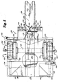
- Figure 5 is a top view of one of the bogies of Figure 1.
- Figure 6 is a side view of one of the bogies and one of the trailers of Figure 1, shown in the process of converting from roadway mode of operation to railway mode of operation.
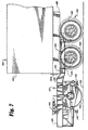
- Figure 7 is a side view of one of the bogies and one of the trailers of Figure 1, shown in the process of converting from roadway mode of operation to railway mode of operation, with the bogie rigidly coupled to the trailer, the roadway tires of the trailer on the ground, and the bogie lifted off the ground.
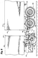
- Figure 8 is a side view of one of the bogies and two of the trailers of Figure 1 configured in the railway mode of operation, with the bogie rigidly coupled to a first trailer and pivotally coupled to a second trailer, the railway wheels of the bogie on a railway, and the roadway tires of the first trailer retracted.
- Figures 9A through 9P illustrate a method in accordance with the present invention of assembling a train of vehicles of the type shown in Figure 1.
- Figure 10 is a back view of one of the bogies of Figure 1.
- Figure 11 is a section view along line 11-11 of Figure 10.
- Figure 12 is a block diagram of the braking system on one of the bogies of Figure 1.
- a train 113 is made of bimodal convertible roadway-railway trailers 160 and bogies 120.
- Trailers 160 can be used both on a roadway and, in conjunction with bogies 120, on a railway 102.
- a single operator can conveniently use a tractor 114 to convert a trailer 160 between roadway and railway operating modes at any grade crossing. No special ramps are required and the removable bogies 120 can be stored at any convenient location, including storage areas located off the railway 102.
- each trailer 160 Secured to the bottom 164 of each trailer 160 is a retractable roadway tire assembly 166 operated by an airbag assembly 171 (see Figures 2-3).
- the tractor 114 is used to move a first trailer 160 and to position the posterior end 162 of the trailer 160 over forward end 124 of a first bogie 120, rigidly coupling the first trailer 160 to the first bogie 120 (see Figures 9A-9B).
- the airbag assembly 171 is inflated, extending the roadway tire assembly 166 away from the bottom 164 of the trailer 160 and lifting the bogie 120 off the ground 105 (see Figure 9C).
- the tractor 114 is used to move the trailer 160 and the bogie 120 to a position over the railway 102, and then the airbag assembly 171 is deflated.
- each trailer 160 has a main body 161, an anterior end 163, a posterior end 162 and a bottom 164.
- a trailer bumper 169 is attached to and transversely extends below the bottom 164 of the trailer 160 at the posterior end 162. Attached to the bumper 169 are lights (not shown).
- the trailer 160 is fitted with brake piping (not shown) which carries pressurized air for use in operating conventional air brakes (also not shown).
- brake piping (not shown) which carries pressurized air for use in operating conventional air brakes (also not shown).
- Secured to the bottom 164 of the trailer 160 at the posterior end 162 are two parallel longitudinal axle supports 165 which extend below the bottom 164.
- a conventional retractable roadway tire assembly 166 is attached to the bottom 164 at the posterior end 162 along the longitudinal axle supports 165.
- the retractable roadway tire assembly 166 comprises two axles 167 both having two roadway tires 168 at each end thereof, and an airbag assembly 171.
- the airbag assembly 171 of conventional design, comprises four airbags 170 having springs (not shown) operably secured therein and stabilizing bars 172 secured thereto. All four airbags 170 together support the posterior end 162 on the axles 167.
- Each airbag-170 is secured at one end thereof to the bottom 164 of the trailer 160 and at the other end thereof to an end of one of the axles 167.
- a stabilizing bar 172 extends between each set of airbags 170, providing stabilization between the axles 167.
- the roadway tires 168 are extended away from the bottom 164, raising the posterior end 162 of the trailer 160.
- the springs (not shown) retract the roadway tires 168 towards the bottom 164.
- the roadway tire assembly 166 can be extended or retracted to any position over its range of extension by inflating or deflating the airbags 170 the desired amount.
- a conventional pin (not shown) can be used to lock the roadway tire assembly 166 at preset extended or retracted positions for use when the trailer 160 travels over a roadway or a railway, as will be discussed below.
- a downwardly oriented center king pin 184 is secured to the bottom 164 in the middle of the roadway tire assembly 166.
- the center king pin 184 is located equidistant between the sides of the trailer 160 so as to roughly balance the weight of the trailer 160 and its load on either side of the center king pin 184.
- the location of the center king pin 184 is forwardly offset from the posterior end 162 of the trailer 160, as will be discussed shortly.
- the center king pin 184 is of conventional design and is constructed for engagement with a V-slot on a bogie. Rearward of the center king pin 184, along the posterior end 162, two downwardly oriented side king pins 185 are secured to the bottom 164.
- the side king pins 185 are offset from each other and are centered between the sides of the trailer 160.
- the side king pins 185 also of conventional design, are constructed for engagement with locking king pin slots on a bogie.
- the center king pin 184 and the side king pins 185 are located at the vertices of a triangle that is approximately equilateral, providing the posterior end 162 of the trailer 160 with multiple spaced-apart connecting mechanisms.
- These three king pins are constructed and arranged for rigidly coupling the trailer 160 to a bogie, functioning as a trailer rigid coupling mechanism.
- a downwardly oriented pivot coupling king pin 192 is secured to the bottom 164 equidistant between the sides of the trailer 160.
- the pivot coupling king pin 192 is of conventional design and is constructed for engagement with a fifth wheel for pivotally coupling the trailer 160 to a second bogie, an engine or a tractor.
- the pivot coupling king pin 192 functions as a trailer pivot coupling mechanism.
- the trailer 160 Rearward of the pivot coupling king pin 192, at the anterior end 163, the trailer 160 has conventional landing gear 174 secured to the bottom 164.
- the landing gear 174 when lowered, supports the anterior end 163 of the trailer 160.
- each bogie 120 includes a metal frame 122 having a narrow forward end 124 and a rearward end 126.
- the forward end 124 is at a lower height than the rest of the frame 122 (see Figures 4 and 11) because the forward end 124 is designed to fit beneath the bumper 169 on the posterior end 162 of a trailer 160, while the rearward end 126 is designed to fit beneath the anterior end 163 of a trailer 160 which does not have a bumper on the bottom 164 thereof.
- a railway wheel assembly 127 is located underneath the frame 122 approximately midway between the forward end 124 and the rearward end 126 and is secured thereto for supporting the frame 122 for motion.
- the railway wheel assembly 127 comprises an air braking system 129 and a lightweight yet sturdy suspension 132.
- the suspension 132 is connected to and supports an axle 128 with railway wheels 130 at each end thereof.
- the suspension 132 comprises a pair of vertically oriented coil springs 133 at each of the axle 128 which extend between the axle 128 and the underside of the frame 122.
- two sets of dampers comprising conventional shock absorbers, are provided.
- a pair of vertical dampers 131 extend upwardly from the opposite ends of the axle 128 and are secured to the frame 122.
- a pair of longitudinal dampers 134 extend rearwardly from the opposite ends of the axle 128 and are each secured to both a first and second set of stabilizing bars 135 and 136.
- the first set of stabilizing bars 135 are secured to the very end of the rearward end 126 of the frame 122 and extend outwardly and downwardly therefrom to the longitudinal dampers 134.
- the second set of stabilizing bars 136 are secured to the rearward end 126 of the frame 122 forward of the very end of the frame 122 and extend outwardly, downwardly and rearwardly to the longitudinal dampers 134.
- the two sets of stabilizing bars 135 and 136 serve as rigid extensions of the frame 122 which allow for the longitudinal dampers 134 to be oriented in a horizontal position parallel to the frame 122 so as to provide for maximum absorption of longitudinal shock.
- the braking system 129 comprises standard freight railcar brake equipment in conjunction with a standard semi-trailer brake air cylinder 129a.
- the air cylinder 129a is a double-acting hydraulic cylinder having two chambers separated by a piston 129m.
- the first chamber is for a main braking subsystem and a second chamber is for a parking braking subsystem, as is described below.
- the external air brake line from a trailer is coupled to the signal air line 129b of the bogie 120 through a glad hand 129c.
- a second glad hand 129c is provided to allow for coupling the signal air line 129b to a second trailer when forming a train.
- a split-off valve 129d splits the air flow from the signal air line 129b into a parking brake line 129e and a regular braking line 129f.
- the regular braking line 129f extends to a standard freight railcar brake valve 129g via a dirt collector and cut out cock 129h.
- the brake valve 129g is configured in a conventional manner, having air inputs coupled by air hoses to an auxiliary reservoir 129i and an emergency reservoir 129j.
- the main braking line 129f couples the brake valve 129g to the first chamber of the air cylinder 129a with air hoses which pass through an empty/load valve 129k and an equalizing volume chamber 129l.
- the brake valve 129g allows air to flow from the auxiliary reservoir 129i through the brake valve 129g and to the first chamber of the air cylinder 129a.
- the brake valve 129g also allows air to flow from the emergency reservoir 129j, increasing the air flow and air pressure to the first chamber of the air cylinder 129a.
- the empty/load valve 129k operates to adjust the air pressure, and thus the braking power, to the first chamber of the air cylinder 129a depending on whether the bogie 120 has an empty or a full load.
- the air cylinder 129a is a standard semi-trailer air brake cylinder while the other components, notably the auxiliary reservoir 129i and the emergency reservoir 129j, are standard freight railcar pieces which have a much larger volume, the equalizing volume chamber 129 l is used to reduce the air pressure to the first chamber of the air cylinder 129a.
- the air cylinder 129a has a piston 129m which is connected to and actuates a braking mechanism 129n. As the pressure in the main braking line 129f and the first chamber of the air cylinder 129a rises, the air cylinder 129a engages and extends the piston 129m. This causes the braking mechanism 129n to engage the railway wheels 130 and apply braking force to the bogie 120.
- the braking system 129 also has a parking brake subsystem.
- the parking brake line 129e extends from the split-off valve 129d to a one-way check valve 129p which allows air to flow only in the direction from the split-off valve 129d.
- the parking brake line 129e extends from the one-way check valve 129p to a tee 129q which splits the parking brake line 129e into two branches.
- the first branch of the parking brake line 129e is coupled to the second chamber of the air cylinder 129a.
- a decrease in the air pressure in the second chamber of the air cylinder 129a causes the piston 129m to extend and engage the braking mechanism 129n.
- the one-way check valve 129p prevents air pressure to the second chamber of the air cylinder 129a from dropping when the pressure in the signal line 129d is falls.
- the second branch of the parking brake line 129e couples the tee 129q to a bait cock 129r which, when opened, releases air into the atmosphere. This reduces pressure in the parking brake line 129e to the second chamber of the air cylinder 129a, thereby engaging the parking brake.
- a bogie landing gear 140 is secured to the underside of the frame 122 for supporting the frame 122 of the bogie 120 in a horizontal position.
- the bogie landing gear 140 comprises two downwardly and outwardly angled landing gear tubes 145, one secured to the frame 122 forward of one railway wheel 130 and the other secured rearward of the opposite railway wheel 130.
- a telescoping landing gear end 139 slides into and out of each landing gear tube 145 and can be locked into place using a conventional release lever (not shown).
- a foot plate 141 Secured to the bottom end of each telescoping landing gear end 139 is a foot plate 141 adapted to resting on the ground.
- the bogie landing gear 140 is lowered when the bogie 120 is to be stored and is raised when the bogie 120 is to be moved or is connected to a trailer 160.
- the forward end 124 of the bogie 120 has a longitudinal V-slot 138 at the center thereof with a wide forward facing opening and a narrow channel having parallel sides.
- the V-slot 138 is designed to receive and hold in place the downwardly oriented center king pin 184 on a trailer 160.
- the wide opening on the V-slot 138 facilitates the alignment of the center king pin 184 with the V-slot 138 and the insertion therein.
- the locking side king pin slots 153 are laterally offset from each other and are designed to received and lock into place the side king pins 185 on a trailer 160.
- the relative positions of the V-slot 138 and the locking side king pin slots 153 correspond to the relative positions of the center king pin 184 and the side king pins 185 on the bottom 164 of a trailer 160.
- the V-slot 138 and the locking side king pin slots 153 are located at the vertices of a triangle that is approximately equilateral, providing the forward end 124 of the bogie 120 with multiple spaced-apart connecting mechanisms.
- These three slots are constructed and arranged for rigidly coupling the bogie 120 to a trailer 160, functioning as a bogie rigid coupling mechanism.
- the locking side king pin slots 153 have a locking mechanism 149 designed to lock the side king pins 185 into the locking side king pin slots 153.
- Each locking side king pin slot 153 comprises a forward facing half-oval opening sized to receive a side king pin 185 and a U-clamp 152 which slides laterally outwardly from the center of the frame 122 and holds a king pin in the middle of the "U" part of the U-clamp 152.
- the U-clamp 152 surrounds the side king pins 185 on the forward, inward and rearward sides, and the frame 122 blocks the outward side and also keeps the U-clamp 152 from being pulled forward. When the U-clamps 152 are slid laterally outwardly, the side king pins 185 sitting in the locking side king pin slots 153 are locked into place.
- a locking lever 151 is pivotally connected to the frame 122 about a pivot point 155 midway between the locking side king pin slots 153. On each side of the pivot point 155, a locking lever engagement bar 158 pivotally connects the locking lever 151 to one of the U-clamps 152.
- the frame 122 has a curved slot 157 through which an extension 156 on the lower part of the locking lever 151 passes, limiting the range of motion of the locking lever 151.
- a spring 150 secured to the frame 122 and the locking lever 151 biases the locking lever 151 so as to keep the U-clamps 152 in a closed position.
- the locking lever engagement bars 158 laterally slide the U-clamps 152 to unlock and lock the locking side king pin slots 153.
- a conventional pin (not shown) can be used to keep the locking lever 151 in an open (unlocked) or a closed (locked) position. The unlocked position is shown in phantom in Figure 5.
- a fifth wheel 148 of conventional design is pivotally mounted on the upper surface 123 of the frame 122 at the rearward end 126 of the bogie 120.
- the fifth wheel 148 is designed for receiving and lockingly engaging a pivot coupling king pin 192' on a second trailer 160'.
- the bogie 120 is pivotally coupled to the second trailer 160'. Because there is only one point of connection between the bogie 120 and the second trailer 160', the second trailer 160' is free to pivot relative to the bogie 120, allowing a train of trailers and bogies to bend when going around curves.
- a single operator can convert a trailer 160 and a bogie 120 into an intermodal railroad car and connect several intermodal railroad cars together to form a train 113.
- a tractor 114 is connected to a first trailer 160 and is driven close to a first bogie 120.
- the bogies are stored off track, near a grade crossing, minimizing cost and effort need to set up a transfer point.
- the landing gear 140 on the bogies are in a lowered position, keeping the bogies from tipping over.
- the locking side king pin slots 153 are opened.
- an operator uses the tractor 114 to back up the first trailer 160 over the forward end 124 of the first bogie 120. Because bogies are small relative to trailers, it is helpful to center the bogies between two indicators so as to assist the operator of the tractor in aligning the trailer 160 over the bogie 120.
- the retractable roadway tire assembly 166 might need to be partially retracted or extended so that the bottom 164 of the first trailer 160 and the forward end 124 of the first bogie 120 are at the same height.
- the landing gear 140 on the first bogie 120 is raised, and the airbag assembly 171 is operated to extend the roadway tires 168 and lift the first bogie 120 off the ground 105.
- the tractor 114 is operated to move the first trailer 160 and the first bogie 120 to a position over a railway 102.
- the airbag assembly 171 is deflated, as is shown in Figure 9E, lowering the posterior end 162 of the first trailer 160 and the first bogie 120 and engaging the railway wheels 130 on the first bogie 120 with the railway 102. As is shown in Figure 9F, the airbag assembly 171 is further deflated, retracting the roadway tires 168. At this point the airbag assembly 171 is locked in place using the conventional locking pin (not shown).
- the landing gear 174 at the anterior end 163 of the first trailer 160 is lowered, and the tractor 114 is uncoupled from the first trailer 160 and driven away.
- a tractor 114' either the same tractor or a different one as before, is used to move a second trailer 160' and a second bogie 120' onto the railway 102.
- the airbag assembly 171' on the second bogie 120' is operated, engaging the railway wheels 130' with the railway 102 and retracting the roadway tires 168'.
- the tractor 114' backs up the second trailer 160' and the second bogie 120' to the anterior end 163 of the first trailer 160.
- the pivot coupling king pin 192 on the anterior end 163 of the first trailer 160 is engaged with the fifth wheel 148' of the second bogie 120' and is lockingly engaged therein, pivotally coupling the second bogie 120' to the first trailer 160.
- the hoses for the braking system on the second bogie 120' (not shown) are connected to the brake piping (not shown) of the first trailer 160.
- the landing gear 174 on the first trailer 160 is raised.
- the tractor 114' is used to back up all of the bogies and trailers along the railway 102.
- a locomotive engine 112 having a fifth wheel 111 on a back end thereof is coupled to the pivot coupling king pin 192" on the anterior end 163" of a last trailer 160" at the front of the train 113.
- the engine 112 could be a conventional train locomotive which has been modified to have a fifth wheel 111, a Brandt Road Rail Power Unit manufactured by Brandt Industries Ltd., a puller as described in commonly owned U.S. Patent application serial number 08/054,906, or any other type of locomotive power, either directly or through a special bogie 120x having a fifth wheel at one end and a standard railroad coupling mechanism at the other end, as is shown in Figure 1B.
- the landing gear 174" on the last trailer 160" is raised and the train 113 is ready to be used on the railway 102.
- the process for disassembling a train 113 of trailers and bogies is similar.
- the landing gear 174' at the anterior end 163' of a first trailer 160' (located at the front of the train 113) is lowered, and an engine 112 is uncoupled.
- a tractor 114' backs up to the anterior end 163' of the first trailer 160', and a fifth wheel 117' on the tractor 114' lockingly engages the pivot coupling king pin 192' on the anterior end 163' of the first trailer 160'.
- the landing gear 174' on the first trailer 160' is raised, and the train 113 can be pulled forwards.
- the landing gear 174 on a second trailer 160 located behind the first trailer 160' is lowered.
- a first bogie 120' is uncoupled from the second trailer 160, and the tractor 114' pulls the first trailer 160' and the first bogie 120' away from the second trailer 160 and the rest of the train 113.
- the roadway tires 168' on the first trailer 160' are extended, raising the first bogie 120' off the railway 102.
- the tractor 114' pulls the first trailer 160' and the first bogie 120' to a storage area located off the tracks 102 and near a grade crossing.
- the roadway tires 168' on the first trailer 160' are retracted, lowering the first bogie 120' to the ground 105.
- the landing gear 140' on the first bogie 120' is extended and the first bogie 120' is uncoupled from the first trailer 160'.
- the tractor 114' pulls the first trailer 160' away from the first bogie 120', leaving it in the storage area. This process is repeated to remove all of the trailers from the railway 102 and leave all of the bogies in the storage area.
Landscapes
- Engineering & Computer Science (AREA)
- Mechanical Engineering (AREA)
- Transportation (AREA)
- Automatic Assembly (AREA)
- Vehicle Body Suspensions (AREA)
- Regulating Braking Force (AREA)
Priority Applications (1)
| Application Number | Priority Date | Filing Date | Title |
|---|---|---|---|
| DE1994634508 DE69434508T2 (de) | 1994-08-08 | 1994-08-08 | Drehgestell-Kupplungssystem für ein umwandelbares Schiene-Strasse- Fahrzeug |
Applications Claiming Priority (1)
| Application Number | Priority Date | Filing Date | Title |
|---|---|---|---|
| EP94932172A EP0783423B1 (fr) | 1994-08-08 | 1994-08-08 | Systeme de raccordement de bogie destine a un vehicule convertible rail/route |
Related Parent Applications (2)
| Application Number | Title | Priority Date | Filing Date |
|---|---|---|---|
| EP94932172A Division EP0783423B1 (fr) | 1994-08-08 | 1994-08-08 | Systeme de raccordement de bogie destine a un vehicule convertible rail/route |
| EP94932172.3 Division | 1996-02-22 |
Publications (3)
| Publication Number | Publication Date |
|---|---|
| EP1145928A2 true EP1145928A2 (fr) | 2001-10-17 |
| EP1145928A3 EP1145928A3 (fr) | 2001-11-07 |
| EP1145928B1 EP1145928B1 (fr) | 2005-10-12 |
Family
ID=8218878
Family Applications (1)
| Application Number | Title | Priority Date | Filing Date |
|---|---|---|---|
| EP01114481A Expired - Lifetime EP1145928B1 (fr) | 1994-08-08 | 1994-08-08 | Système de raccordement de bogie destiné à un véhicule convertible rail/route |
Country Status (2)
| Country | Link |
|---|---|
| EP (1) | EP1145928B1 (fr) |
| DK (1) | DK1145928T3 (fr) |
Cited By (2)
| Publication number | Priority date | Publication date | Assignee | Title |
|---|---|---|---|---|
| RU2651360C2 (ru) * | 2016-03-22 | 2018-04-19 | Общество с ограниченной ответственностью Управляющая Компания "РэйлТрансХолдинг" | Грузовой вагон сочлененный |
| CN111907534A (zh) * | 2020-09-07 | 2020-11-10 | 中铁宝桥集团有限公司 | 一种单轨观光车悬架装置 |
Families Citing this family (1)
| Publication number | Priority date | Publication date | Assignee | Title |
|---|---|---|---|---|
| AR064813A1 (es) | 2006-12-20 | 2009-04-29 | Railrunner Na Inc | Chasis de contenedor bimodal |
Citations (4)
| Publication number | Priority date | Publication date | Assignee | Title |
|---|---|---|---|---|
| US4448132A (en) | 1981-09-17 | 1984-05-15 | Beatty William T | Convertible railway-highway vehicle |
| US4917020A (en) | 1988-09-14 | 1990-04-17 | The Chamberlain Group, Inc. | Transition vehicle for use with convertible rail-highway trailers |
| US5009169A (en) | 1988-03-15 | 1991-04-23 | Jacques Viens | Twin axle rail bogie for convertible rail-highway vehicles |
| US5220870A (en) | 1992-05-26 | 1993-06-22 | Larson Ernest J | Convertible highway-railway hauling vehicle |
Family Cites Families (4)
| Publication number | Priority date | Publication date | Assignee | Title |
|---|---|---|---|---|
| DE961714C (de) * | 1953-08-06 | 1957-04-11 | Schoema Christoph Schoettler M | Wegwechselfahrzeug mit austauschbaren Untersetzgestellen fuer Schienen- oder Strassenfahrt |
| US4416571A (en) * | 1981-02-17 | 1983-11-22 | Krause Robert A | Truck and rail transportation system |
| NO159523C (no) * | 1983-11-23 | 1989-01-11 | Trailer Train Ltd | Transportsystem omfattende semitrailere og skinneboggier,samt skinnetog omfattende flere slike semitrailere. |
| NL9100577A (nl) * | 1990-11-01 | 1992-06-01 | Alpha Eng Stork | Universele oplegger. |
-
1994
- 1994-08-08 DK DK01114481T patent/DK1145928T3/da active
- 1994-08-08 EP EP01114481A patent/EP1145928B1/fr not_active Expired - Lifetime
Patent Citations (4)
| Publication number | Priority date | Publication date | Assignee | Title |
|---|---|---|---|---|
| US4448132A (en) | 1981-09-17 | 1984-05-15 | Beatty William T | Convertible railway-highway vehicle |
| US5009169A (en) | 1988-03-15 | 1991-04-23 | Jacques Viens | Twin axle rail bogie for convertible rail-highway vehicles |
| US4917020A (en) | 1988-09-14 | 1990-04-17 | The Chamberlain Group, Inc. | Transition vehicle for use with convertible rail-highway trailers |
| US5220870A (en) | 1992-05-26 | 1993-06-22 | Larson Ernest J | Convertible highway-railway hauling vehicle |
Cited By (2)
| Publication number | Priority date | Publication date | Assignee | Title |
|---|---|---|---|---|
| RU2651360C2 (ru) * | 2016-03-22 | 2018-04-19 | Общество с ограниченной ответственностью Управляющая Компания "РэйлТрансХолдинг" | Грузовой вагон сочлененный |
| CN111907534A (zh) * | 2020-09-07 | 2020-11-10 | 中铁宝桥集团有限公司 | 一种单轨观光车悬架装置 |
Also Published As
| Publication number | Publication date |
|---|---|
| DK1145928T3 (da) | 2006-02-13 |
| EP1145928A3 (fr) | 2001-11-07 |
| EP1145928B1 (fr) | 2005-10-12 |
Similar Documents
| Publication | Publication Date | Title |
|---|---|---|
| US5826517A (en) | Bogie coupling system for convertible railway-railroad vehicle | |
| US5375532A (en) | Convertible railway-roadway vehicle and method of use | |
| US4917020A (en) | Transition vehicle for use with convertible rail-highway trailers | |
| US5220870A (en) | Convertible highway-railway hauling vehicle | |
| US6460468B1 (en) | Intermodal transport system | |
| US5020445A (en) | Truck-train system for transporting truck trailers along rails using railway dollies | |
| US5291835A (en) | Retractable intermodal vehicle | |
| US4773336A (en) | Railroad bogie for removably supporting coupled semi-trailers | |
| GB2178385A (en) | Making a train of highway trailers | |
| US4955292A (en) | Dual-mode rail-highway semi-trailer with separable bogie | |
| GB2070531A (en) | Air-spring suspension for rail or road vehicle | |
| EP1539513B1 (fr) | Vehicule convertible rail/route, et son mode de conduite | |
| US5040466A (en) | Train of highway trailers and method of making | |
| EP0783423B1 (fr) | Systeme de raccordement de bogie destine a un vehicule convertible rail/route | |
| EP1145928B1 (fr) | Système de raccordement de bogie destiné à un véhicule convertible rail/route | |
| US20070089637A1 (en) | Apparatus and method for intermodal conversion of transport vehicles; rail-to-highway and highway-to-rail | |
| US4981083A (en) | Dual-mode rail-highway semi-trailer | |
| US20060288902A1 (en) | Intermodal rail car/truck trailer | |
| RU2171191C2 (ru) | Система сцепления тележки для преобразуемого железнодорожно-шоссейного транспортного средства | |
| US2981209A (en) | Combination rail-highway freight and auto transport | |
| US4869177A (en) | Rail-highway semitrailer | |
| BE1014746A3 (nl) | Werkwijze voor het transporteren van vrachten en transportvoertuig dat daarvoor kan worden aangewend. | |
| US20080105159A1 (en) | Reinforced Bi-Modal Open Top Trash/Refuse Trailer | |
| CN2412791Y (zh) | 公路铁路两用货运车 | |
| HK1057519B (en) | Convertible railway-roadway vehicle and method of use |
Legal Events
| Date | Code | Title | Description |
|---|---|---|---|
| PUAI | Public reference made under article 153(3) epc to a published international application that has entered the european phase |
Free format text: ORIGINAL CODE: 0009012 |
|
| PUAL | Search report despatched |
Free format text: ORIGINAL CODE: 0009013 |
|
| AC | Divisional application: reference to earlier application |
Ref document number: 783423 Country of ref document: EP |
|
| AK | Designated contracting states |
Kind code of ref document: A2 Designated state(s): BE CH DE DK FR GB IT LI |
|
| AK | Designated contracting states |
Kind code of ref document: A3 Designated state(s): BE CH DE DK FR GB IT LI |
|
| 17P | Request for examination filed |
Effective date: 20020506 |
|
| AKX | Designation fees paid |
Free format text: BE CH DE DK FR GB IT LI |
|
| 17Q | First examination report despatched |
Effective date: 20021218 |
|
| GRAP | Despatch of communication of intention to grant a patent |
Free format text: ORIGINAL CODE: EPIDOSNIGR1 |
|
| GRAS | Grant fee paid |
Free format text: ORIGINAL CODE: EPIDOSNIGR3 |
|
| GRAA | (expected) grant |
Free format text: ORIGINAL CODE: 0009210 |
|
| AC | Divisional application: reference to earlier application |
Ref document number: 0783423 Country of ref document: EP Kind code of ref document: P |
|
| AK | Designated contracting states |
Kind code of ref document: B1 Designated state(s): BE CH DE DK FR GB IT LI |
|
| REG | Reference to a national code |
Ref country code: GB Ref legal event code: FG4D |
|
| REG | Reference to a national code |
Ref country code: CH Ref legal event code: EP |
|
| REG | Reference to a national code |
Ref country code: DK Ref legal event code: T3 |
|
| REG | Reference to a national code |
Ref country code: CH Ref legal event code: NV Representative=s name: HEPP, WENGER & RYFFEL AG |
|
| REF | Corresponds to: |
Ref document number: 69434508 Country of ref document: DE Date of ref document: 20060223 Kind code of ref document: P |
|
| ET | Fr: translation filed | ||
| PLBE | No opposition filed within time limit |
Free format text: ORIGINAL CODE: 0009261 |
|
| STAA | Information on the status of an ep patent application or granted ep patent |
Free format text: STATUS: NO OPPOSITION FILED WITHIN TIME LIMIT |
|
| 26N | No opposition filed |
Effective date: 20060713 |
|
| PGFP | Annual fee paid to national office [announced via postgrant information from national office to epo] |
Ref country code: DK Payment date: 20090714 Year of fee payment: 16 Ref country code: FR Payment date: 20090806 Year of fee payment: 16 |
|
| PGFP | Annual fee paid to national office [announced via postgrant information from national office to epo] |
Ref country code: DE Payment date: 20090831 Year of fee payment: 16 Ref country code: CH Payment date: 20090811 Year of fee payment: 16 Ref country code: GB Payment date: 20090708 Year of fee payment: 16 |
|
| PGFP | Annual fee paid to national office [announced via postgrant information from national office to epo] |
Ref country code: BE Payment date: 20090910 Year of fee payment: 16 |
|
| PGFP | Annual fee paid to national office [announced via postgrant information from national office to epo] |
Ref country code: IT Payment date: 20090813 Year of fee payment: 16 |
|
| BERE | Be: lapsed |
Owner name: *LARSON ERNEST J. JR. Effective date: 20100831 |
|
| REG | Reference to a national code |
Ref country code: DK Ref legal event code: EBP |
|
| REG | Reference to a national code |
Ref country code: CH Ref legal event code: PL |
|
| GBPC | Gb: european patent ceased through non-payment of renewal fee |
Effective date: 20100808 |
|
| PG25 | Lapsed in a contracting state [announced via postgrant information from national office to epo] |
Ref country code: CH Free format text: LAPSE BECAUSE OF NON-PAYMENT OF DUE FEES Effective date: 20100831 Ref country code: LI Free format text: LAPSE BECAUSE OF NON-PAYMENT OF DUE FEES Effective date: 20100831 |
|
| REG | Reference to a national code |
Ref country code: FR Ref legal event code: ST Effective date: 20110502 |
|
| PG25 | Lapsed in a contracting state [announced via postgrant information from national office to epo] |
Ref country code: IT Free format text: LAPSE BECAUSE OF NON-PAYMENT OF DUE FEES Effective date: 20100808 |
|
| REG | Reference to a national code |
Ref country code: DE Ref legal event code: R119 Ref document number: 69434508 Country of ref document: DE Effective date: 20110301 |
|
| PG25 | Lapsed in a contracting state [announced via postgrant information from national office to epo] |
Ref country code: DE Free format text: LAPSE BECAUSE OF NON-PAYMENT OF DUE FEES Effective date: 20110301 Ref country code: FR Free format text: LAPSE BECAUSE OF NON-PAYMENT OF DUE FEES Effective date: 20100831 Ref country code: BE Free format text: LAPSE BECAUSE OF NON-PAYMENT OF DUE FEES Effective date: 20100831 |
|
| PG25 | Lapsed in a contracting state [announced via postgrant information from national office to epo] |
Ref country code: DK Free format text: LAPSE BECAUSE OF NON-PAYMENT OF DUE FEES Effective date: 20100831 Ref country code: GB Free format text: LAPSE BECAUSE OF NON-PAYMENT OF DUE FEES Effective date: 20100808 |