EP1145939A2 - Véhicule de travail et cabine de conduite - Google Patents
Véhicule de travail et cabine de conduite Download PDFInfo
- Publication number
- EP1145939A2 EP1145939A2 EP01107975A EP01107975A EP1145939A2 EP 1145939 A2 EP1145939 A2 EP 1145939A2 EP 01107975 A EP01107975 A EP 01107975A EP 01107975 A EP01107975 A EP 01107975A EP 1145939 A2 EP1145939 A2 EP 1145939A2
- Authority
- EP
- European Patent Office
- Prior art keywords
- operators
- work vehicle
- operators cab
- cab
- post
- Prior art date
- Legal status (The legal status is an assumption and is not a legal conclusion. Google has not performed a legal analysis and makes no representation as to the accuracy of the status listed.)
- Granted
Links
- 238000011161 development Methods 0.000 description 2
- 230000018109 developmental process Effects 0.000 description 2
- 206010050031 Muscle strain Diseases 0.000 description 1
- 229910000831 Steel Inorganic materials 0.000 description 1
- 238000004378 air conditioning Methods 0.000 description 1
- 230000001419 dependent effect Effects 0.000 description 1
- 238000010438 heat treatment Methods 0.000 description 1
- 239000010959 steel Substances 0.000 description 1
Images
Classifications
-
- B—PERFORMING OPERATIONS; TRANSPORTING
- B66—HOISTING; LIFTING; HAULING
- B66C—CRANES; LOAD-ENGAGING ELEMENTS OR DEVICES FOR CRANES, CAPSTANS, WINCHES, OR TACKLES
- B66C13/00—Other constructional features or details
- B66C13/52—Details of compartments for driving engines or motors or of operator's stands or cabins
- B66C13/54—Operator's stands or cabins
-
- A—HUMAN NECESSITIES
- A01—AGRICULTURE; FORESTRY; ANIMAL HUSBANDRY; HUNTING; TRAPPING; FISHING
- A01B—SOIL WORKING IN AGRICULTURE OR FORESTRY; PARTS, DETAILS, OR ACCESSORIES OF AGRICULTURAL MACHINES OR IMPLEMENTS, IN GENERAL
- A01B63/00—Lifting or adjusting devices or arrangements for agricultural machines or implements
-
- E—FIXED CONSTRUCTIONS
- E02—HYDRAULIC ENGINEERING; FOUNDATIONS; SOIL SHIFTING
- E02F—DREDGING; SOIL-SHIFTING
- E02F9/00—Component parts of dredgers or soil-shifting machines, not restricted to one of the kinds covered by groups E02F3/00 - E02F7/00
- E02F9/20—Drives; Control devices
- E02F9/2004—Control mechanisms, e.g. control levers
Definitions
- the invention is directed to an operators cab according to the pre-characterizing part of claim 1 and to a work vehicle according to the pre-characterizing part of claim 1.
- Work vehicles are designed to perform a work operation. Many work vehicles are designed to pull a large body behind the vehicle. Examples of vehicles designed to pull a large body, include logging skidders and agricultural tractors. It has been found that an operator of a logging skidder may spend sixty (percent) of his or her time looking forward and forty (percent) of his or her time looking rearward to check the log skidding operation.
- ROPS roll over protection system
- a work vehicle having a supporting frame and ground engaging wheels is provided with a work implement mounted to the rear portion of the work vehicle.
- the work implement is designed to drag a body behind the vehicle.
- the operation of the work vehicle is controlled from an operators cab mounted to the supporting frame.
- the operators cab is provided with a ROPS for protecting the operator.
- the ROPS is provided with four vertically extending supporting posts, left and right front supporting posts, and left and right rear supporting posts.
- An operators seat is located in the operators cab and is arranged diagonally to the longitudinal centerline of the vehicle. In the preferred embodiment, the operators seat faces both to the front and to the right side.
- the right rear corner post is provided with at least one operator control that is in the line of sight of the operator when seated in the operators seat.
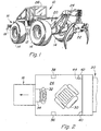
- FIG. 1 illustrates an off road work vehicle which in the present example is a grapple skidder 10.
- the grapple skidder 10 is provided with a supporting frame 12 having ground engaging means 14 for supporting and propelling the vehicle.
- the illustrated embodiment discloses a vehicle having ground engaging wheels, the present invention could also be used on track laying vehicles of either the steel tracked type or the rubber tracked type.
- the supporting frame 12 is provided with a front portion 16 having a front mounted stacking blade 18, and a rear portion 20 having a rear mounted grapple 22 and associated grapple linkage 24. The operation of the vehicle is controlled from an operator cab 26.
- the grapple 22 and grapple linkage 24 comprise a work implement for performing a work operation.
- the work operation is grabbing and dragging logs behind the skidder 10.
- Cable skidders perform the identical work operation except that a cable and choker is used to grab the logs.
- the rear portion mounted work implement comprises a hitch for dragging an implement behind the tractor through a field.
- the supporting frame 12 of the work vehicle defines a longitudinal center line that passes through the front portion 16 and the rear portion 20.
- the operators cab 26 is provided with an operators seat 30 which is diagonal to the longitudinal center line of the vehicle. More specifically in the preferred embodiment, the seat 30 is faced forward and to the right to minimize operator neck strain and fatigue. It should be noted that in the illustrated embodiment, the seat 30 intersects the longitudinal centerline, however, the seat 30 could be diagonally arranged and offset from the line.
- the operator steers the vehicle by manipulating steering wheel 32 which extends upwardly and rearwardly from front console 34.
- the front console may be provided with controls for controlling the operation of the work vehicle.
- the operators cab is provided with left and right front supporting posts 36 and 38, respectively, and left and right rear supporting posts 40 and 42, respectively. These supporting posts 36 - 42 form part of the ROPS structure for the operators cab 26.
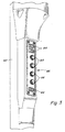
- operator controls 44 are mounted to the right rear post 42.
- the right rear post defines a silhouette when the operator is in the operators seat 30.
- the operator controls 44 are located within this silhouette so they do not interfere with the operators visibility. By locating these controls on the right rear post 42 the controls are within the operators line of sight when seated. In addition, damage to the controls is minimized by reducing their exposure. By locating the controls on the post they are more easily serviced and maintained. Furthermore, the number of controls located on the front console is reduced better facilitating their arrangement on the front console.
- the operators seat 30 faces right and the operator controls are mounted on the right rear corner post 42.
- the seat could also be diagonally arranged to the left and the controls mounted on the left rear corner post 40.
- the invention should not be limited to the above described embodiments, but should be limited solely to the claims.
Landscapes
- Engineering & Computer Science (AREA)
- Life Sciences & Earth Sciences (AREA)
- Mechanical Engineering (AREA)
- Soil Sciences (AREA)
- Environmental Sciences (AREA)
- Mining & Mineral Resources (AREA)
- Civil Engineering (AREA)
- General Engineering & Computer Science (AREA)
- Structural Engineering (AREA)
- Body Structure For Vehicles (AREA)
- Component Parts Of Construction Machinery (AREA)
Applications Claiming Priority (2)
| Application Number | Priority Date | Filing Date | Title |
|---|---|---|---|
| US546471 | 1991-05-13 | ||
| US09/546,471 US6286897B1 (en) | 2000-04-10 | 2000-04-10 | Mounting controls on right rear corner post of operators cab |
Publications (3)
| Publication Number | Publication Date |
|---|---|
| EP1145939A2 true EP1145939A2 (fr) | 2001-10-17 |
| EP1145939A3 EP1145939A3 (fr) | 2003-10-29 |
| EP1145939B1 EP1145939B1 (fr) | 2008-03-19 |
Family
ID=24180565
Family Applications (1)
| Application Number | Title | Priority Date | Filing Date |
|---|---|---|---|
| EP01107975A Expired - Lifetime EP1145939B1 (fr) | 2000-04-10 | 2001-03-29 | Véhicule de travail et cabine de conduite |
Country Status (3)
| Country | Link |
|---|---|
| US (1) | US6286897B1 (fr) |
| EP (1) | EP1145939B1 (fr) |
| DE (1) | DE60133236T2 (fr) |
Families Citing this family (9)
| Publication number | Priority date | Publication date | Assignee | Title |
|---|---|---|---|---|
| JP3558561B2 (ja) * | 1999-08-25 | 2004-08-25 | 株式会社クボタ | トラクタ |
| US6793256B2 (en) | 2001-12-17 | 2004-09-21 | Jsp Licenses, Inc. | Vehicle bumper energy absorber system and method |
| US6582000B1 (en) * | 2002-01-29 | 2003-06-24 | International Truck Intellectual Property Company, Llc | Monolithic trim panel with integrated speaker grill |
| US6942282B1 (en) * | 2004-06-17 | 2005-09-13 | Cnh America Llc | Wrap-around cab control layout for bale wagon |
| JP2013021975A (ja) * | 2011-07-21 | 2013-02-04 | Kubota Corp | コンバイン |
| JP5797962B2 (ja) * | 2011-07-21 | 2015-10-21 | 株式会社クボタ | コンバイン |
| JP5921791B1 (ja) * | 2015-06-08 | 2016-05-24 | 株式会社小松製作所 | キャブおよびブルドーザ |
| JP5956103B1 (ja) * | 2016-02-19 | 2016-07-20 | 株式会社小松製作所 | ブルドーザ |
| CN111591361A (zh) * | 2020-05-14 | 2020-08-28 | 贵州理工学院 | 一种纯电驱动履带式田间鲜烟叶搬运机 |
Family Cites Families (9)
| Publication number | Priority date | Publication date | Assignee | Title |
|---|---|---|---|---|
| DE2228392A1 (de) * | 1972-06-10 | 1974-01-03 | Kloeckner Humboldt Deutz Ag | Fahrerstand, insbesondere fuer landund/oder bauwirtschaftlich nutzbare motorfahrzeuge |
| US4266625A (en) * | 1978-01-16 | 1981-05-12 | Melroe Multi-Wheel | Traction vehicle |
| US4372410A (en) * | 1980-11-10 | 1983-02-08 | Fiat-Allis Construction Machinery, Inc. | Modular instrument console |
| US4505358A (en) * | 1982-01-11 | 1985-03-19 | Ulrich Sielaff | Voice communicator |
| GB2136366B (en) * | 1983-03-11 | 1986-07-09 | United Motor Works | Tractor canopies |
| IT206791Z2 (it) * | 1986-01-20 | 1987-10-01 | Breganze Vicenza A | Cruscotto ausiliario per cabine di macchine operatrici particolarmente per macchine agricole |
| US5052512A (en) * | 1990-08-14 | 1991-10-01 | Ford New Holland, Inc. | Reversible control level linkage |
| DE4308556A1 (de) * | 1993-03-18 | 1994-09-22 | Pietzsch Automatisierungstech | Bedienplatz für Fahrzeuge oder Arbeitsgeräte |
| DE29723095U1 (de) * | 1997-06-12 | 1998-03-26 | Schatz, Werner, 72631 Aichtal | Flurförderfahrzeug |
-
2000
- 2000-04-10 US US09/546,471 patent/US6286897B1/en not_active Expired - Lifetime
-
2001
- 2001-03-29 EP EP01107975A patent/EP1145939B1/fr not_active Expired - Lifetime
- 2001-03-29 DE DE60133236T patent/DE60133236T2/de not_active Expired - Fee Related
Non-Patent Citations (1)
| Title |
|---|
| None |
Also Published As
| Publication number | Publication date |
|---|---|
| DE60133236D1 (de) | 2008-04-30 |
| EP1145939A3 (fr) | 2003-10-29 |
| US6286897B1 (en) | 2001-09-11 |
| DE60133236T2 (de) | 2009-04-23 |
| EP1145939B1 (fr) | 2008-03-19 |
Similar Documents
| Publication | Publication Date | Title |
|---|---|---|
| CA1092423A (fr) | Tracteur a cabine basculante climatisee | |
| CA2505458C (fr) | Tracteur a poste de conduite reversible pour operation et transport | |
| US6390764B1 (en) | Vehicle operable as both a lifting machine and an agricultural tractor | |
| CZ280611B6 (cs) | Pracovní vozidlo | |
| US7347488B2 (en) | Vehicle cab including centrally-located “A post” | |
| EP3640126B1 (fr) | Véhicule radiocommandé multifonctions | |
| US20050252183A1 (en) | Agricultural cutter comprising a carrier vehicle and several work units | |
| CA2307926C (fr) | Tracteur agricole multifonctionnel autopropulse | |
| EP1145939B1 (fr) | Véhicule de travail et cabine de conduite | |
| US8739650B2 (en) | Control lever device for work vehicle | |
| US5071187A (en) | Overhead guard for lift trucks | |
| US6431303B1 (en) | Cab for earth-moving machines | |
| US5738155A (en) | Tree stump cutting apparatus | |
| US6711839B1 (en) | Tractor with a working implement | |
| US10099640B1 (en) | Pivoting bumper for vehicle | |
| EP1061187A1 (fr) | Véhicule de manutention de matériaux | |
| EP1123647B1 (fr) | Tracteur agricole à position de conduite latérale | |
| EP0904969B1 (fr) | Plate-forme de conduite, capot et réservoir de carburant pour petit tracteur permettant une visibilité maximale pour le conducteur | |
| US4930589A (en) | Operator guidebar for a walk-beside articulated machine | |
| US11370289B2 (en) | Work vehicle | |
| JPH0629172Y2 (ja) | トラクタの油圧装置における配管取付装置 | |
| JPH0220151Y2 (fr) | ||
| JPH0730726Y2 (ja) | 路面切削装置付トラック | |
| JPH0515207A (ja) | 乗用型作業機 | |
| JPS60139574A (ja) | トラクタの安全フレ−ム取付装置 |
Legal Events
| Date | Code | Title | Description |
|---|---|---|---|
| PUAI | Public reference made under article 153(3) epc to a published international application that has entered the european phase |
Free format text: ORIGINAL CODE: 0009012 |
|
| AK | Designated contracting states |
Kind code of ref document: A2 Designated state(s): AT BE CH CY DE DK ES FI FR GB GR IE IT LI LU MC NL PT SE TR |
|
| AX | Request for extension of the european patent |
Free format text: AL;LT;LV;MK;RO;SI |
|
| PUAL | Search report despatched |
Free format text: ORIGINAL CODE: 0009013 |
|
| AK | Designated contracting states |
Kind code of ref document: A3 Designated state(s): AT BE CH CY DE DK ES FI FR GB GR IE IT LI LU MC NL PT SE TR |
|
| AX | Request for extension of the european patent |
Extension state: AL LT LV MK RO SI |
|
| RIC1 | Information provided on ipc code assigned before grant |
Ipc: 7B 62D 33/06 A Ipc: 7B 60H 3/06 B |
|
| 17P | Request for examination filed |
Effective date: 20040429 |
|
| AKX | Designation fees paid |
Designated state(s): DE FR GB IT SE |
|
| GRAP | Despatch of communication of intention to grant a patent |
Free format text: ORIGINAL CODE: EPIDOSNIGR1 |
|
| GRAS | Grant fee paid |
Free format text: ORIGINAL CODE: EPIDOSNIGR3 |
|
| GRAA | (expected) grant |
Free format text: ORIGINAL CODE: 0009210 |
|
| AK | Designated contracting states |
Kind code of ref document: B1 Designated state(s): DE FR GB IT SE |
|
| REG | Reference to a national code |
Ref country code: GB Ref legal event code: FG4D |
|
| REF | Corresponds to: |
Ref document number: 60133236 Country of ref document: DE Date of ref document: 20080430 Kind code of ref document: P |
|
| ET | Fr: translation filed | ||
| PLBE | No opposition filed within time limit |
Free format text: ORIGINAL CODE: 0009261 |
|
| STAA | Information on the status of an ep patent application or granted ep patent |
Free format text: STATUS: NO OPPOSITION FILED WITHIN TIME LIMIT |
|
| 26N | No opposition filed |
Effective date: 20081222 |
|
| PGFP | Annual fee paid to national office [announced via postgrant information from national office to epo] |
Ref country code: DE Payment date: 20090220 Year of fee payment: 9 Ref country code: IT Payment date: 20090327 Year of fee payment: 9 Ref country code: SE Payment date: 20090327 Year of fee payment: 9 |
|
| PGFP | Annual fee paid to national office [announced via postgrant information from national office to epo] |
Ref country code: FR Payment date: 20090317 Year of fee payment: 9 |
|
| PGFP | Annual fee paid to national office [announced via postgrant information from national office to epo] |
Ref country code: GB Payment date: 20090403 Year of fee payment: 9 |
|
| EUG | Se: european patent has lapsed | ||
| GBPC | Gb: european patent ceased through non-payment of renewal fee |
Effective date: 20100329 |
|
| REG | Reference to a national code |
Ref country code: FR Ref legal event code: ST Effective date: 20101130 |
|
| PG25 | Lapsed in a contracting state [announced via postgrant information from national office to epo] |
Ref country code: FR Free format text: LAPSE BECAUSE OF NON-PAYMENT OF DUE FEES Effective date: 20100331 |
|
| PG25 | Lapsed in a contracting state [announced via postgrant information from national office to epo] |
Ref country code: DE Free format text: LAPSE BECAUSE OF NON-PAYMENT OF DUE FEES Effective date: 20101001 |
|
| PG25 | Lapsed in a contracting state [announced via postgrant information from national office to epo] |
Ref country code: IT Free format text: LAPSE BECAUSE OF NON-PAYMENT OF DUE FEES Effective date: 20100329 Ref country code: GB Free format text: LAPSE BECAUSE OF NON-PAYMENT OF DUE FEES Effective date: 20100329 |
|
| PG25 | Lapsed in a contracting state [announced via postgrant information from national office to epo] |
Ref country code: SE Free format text: LAPSE BECAUSE OF NON-PAYMENT OF DUE FEES Effective date: 20100330 |