EP1145988A2 - Organe d'activation d'une valve avec élément interne compressible - Google Patents
Organe d'activation d'une valve avec élément interne compressible Download PDFInfo
- Publication number
- EP1145988A2 EP1145988A2 EP01105646A EP01105646A EP1145988A2 EP 1145988 A2 EP1145988 A2 EP 1145988A2 EP 01105646 A EP01105646 A EP 01105646A EP 01105646 A EP01105646 A EP 01105646A EP 1145988 A2 EP1145988 A2 EP 1145988A2
- Authority
- EP
- European Patent Office
- Prior art keywords
- product
- valve
- valve stem
- valve body
- radial orifice
- Prior art date
- Legal status (The legal status is an assumption and is not a legal conclusion. Google has not performed a legal analysis and makes no representation as to the accuracy of the status listed.)
- Withdrawn
Links
Images


Classifications
-
- B—PERFORMING OPERATIONS; TRANSPORTING
- B65—CONVEYING; PACKING; STORING; HANDLING THIN OR FILAMENTARY MATERIAL
- B65D—CONTAINERS FOR STORAGE OR TRANSPORT OF ARTICLES OR MATERIALS, e.g. BAGS, BARRELS, BOTTLES, BOXES, CANS, CARTONS, CRATES, DRUMS, JARS, TANKS, HOPPERS, FORWARDING CONTAINERS; ACCESSORIES, CLOSURES, OR FITTINGS THEREFOR; PACKAGING ELEMENTS; PACKAGES
- B65D83/00—Containers or packages with special means for dispensing contents
- B65D83/14—Containers for dispensing liquid or semi-liquid contents by internal gaseous pressure, i.e. aerosol containers comprising propellant
- B65D83/44—Valves specially adapted for the discharge of contents; Regulating devices
Definitions
- the present invention relates to an improved actuator for a pressurized aerosol valve which has a first low/fine product dispensing spray position and a second high/coarse product dispensing flow position.
- the actuator valve includes an internal compressible component which remains uncompressed, when discharging product in the first low/fine product dispensing spray position, and is compressed, when discharging product in the second high/coarse dispensing position.
- Another object of the present invention is to provide an aerosol valve which has a first low/fine dispensing rate and a second high/coarse product dispensing rate with both product dispensing flow rates being achieved by merely applying downward pressured to the actuator button, e.g. the first low/fine dispensing rate occurs upon initial actuation of the actuator button and the second high/coarse dispensing rate occurs upon further depression of the actuator button of the aerosol valve.
- Yet another object of the present invention is to provide an indication, which is readily detectable by an operator of the valve, so that the operator can instantly sense that any further depression of the valve stem will alter the product dispensing flow rate from the first low/fine product dispensing rate to the second high/coarse product dispensing rate. This facilitates the operator applying sufficient downward dispensing pressure of the aerosol valve to achieve a desired product dispensing flow rate.
- Still another object of the present invention is to locate the compressible member within the valve housing so that the compressible member is always maintained in a proper position for use without requiring any operator manipulation or intervention to alterthe product dispensing flow rate the valve.
- a further object of the present invention is to form the compressible member from an elastomeric material which is readily compressed but re-expands back to original uncompressed state, of the elastomeric material, immediately upon an interruption of the applied compression force.
- the present invention also relates to an improved mounting cup and valve assembly combination for an aerosol canister, the combination comprising:
- the present invention also relates to a pressurized spray canister comprising:
- the present invention finally relates to a method of forming an improved mounting cup and valve assembly combination for an aerosol canister, the method comprising the steps of:
- an aerosol or pressurizable canister 10 generally comprises a base canister 14, defining a product/propellent cavity 15 therein, which has an opening in a top portion of the base canister 14 for receiving a conventional mounting cup 12.
- an actuator assembly 18, typically comprising a vertical depressible valve is crimped to a pedestal portion 34 of the mounting cup 12 in a conventional manner.
- the mounting cup 12, with the supported actuator assembly 18, is installed in an opening in the top of the base canister 14 and an outer periphery of the mounting cup 12 is crimped to the base canister 14 to form the pressurizable canister 10.
- the prod uct/propellent cavity 15 of the pressurizable canister 10 is filled with a desired product to be dispensed 16 as well as a pressurized propellent 17 to facilitate dispensing of the desired product to be dispensed 16, as required by an operator.
- a further detailed description concerning the same is not provided.
- the mounting cup 12 supports the actuator assembly 18.
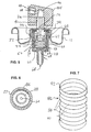
- the actuator assembly 18 comprises a valve body 22 having an internal cavity which supports an upstanding valve stem 26, a biasing spring 28 and a gasket 30.
- the valve stem 26, the biasing spring 28 and the gasket 30 are assembled within the internal cavity 58 of the valve body 22 and this assembly is then clamped or crimped to the mounting cup 12 by means of a plurality of indentations or crimps 32, e.g. four indentations or crimps are formed inwardly from the exterior of the sidewall of the pedestal portion 34 to permanently retain the this assembly to the mounting cup 12.
- the crimping operation forces the valve body 22 slightly upward, relative to the mounting cup 12, to bias and compressively seal the gasket 30 against the inwardly facing surface of the mounting cup 12.
- a portion of the valve stem 26 protrudes through a central aperture 36 provided in the pedestal portion 34 of the mounting cup 12 and supports the actuator button 24.
- the actuator button 24 has a central product inlet or aperture 40 therein which receives and fits over an exterior of the valve stem 26.
- the product inlet 40 communicates with a dispensing outlet 44 of the actuator button 24, via a button cavity 46 and at least one radial supply passageway 48.
- the valve stem 26 includes a central bore 42 having a dispensing end which communicates with product inlet 40.
- the opposite end of the central bore 42 communicates with at least one first radial orifice 50, and possibly two, three, four or more first radial orifices 50 equally spaced about the circumference of the valve stem 26, which are each temporarily blocked from discharging product by a seal formed between the gasket 30 and an annular sealing rib 70 when the valve is in its normally closed position, as can be seen in Fig. 2.
- At least one second radial orifice 52, and possibly two, three, four or more second radial orifices 52 equally spaced about the circumference of the valve stem 26, are also provided in the valve stem 26.
- the second radial orifice(s) 52 is/are spaced axially along the valve stem 26, in the direction of the actuator button 24, and is/are directly covered or blocked by engagement with the gasket 30. A further detailed description concerning the function of second radial orifice(s) 52 will follow below.
- the valve body 22 has a thickened mouth 56.
- the valve body 22 also includes a side wall 60 and a floor wall 62 which is provided with at least one inlet aperture 64, e.g. either a pair of inlet lateral apertures (Fig. 3) or an inlet central aperture (Figs. 5 and 6).
- the plurality of indentations or crimps 32 engage a lower portion of the thickened mouth 56 and force the valve body 28 upwardly so as to compress and seal the gasket 30 against the inwardly facing surface of the mounting cup 12.
- the valve stem 26 includes an enlarged head 66.
- the enlarged head 66 is centrally connected to the valve stem 26 and is formed at the lower end of the valve element.
- An annular recess 67 may be formed in the undersurface of the enlarged head 66 to receive and center a top portion of the spring 28.
- the upwardly facing surface of the enlarged head 66 is provided with an annular sealing rib 70 which normally seats against the lower or downwardly facing surface of the gasket 30 to form a fluid tight seal therebetween.
- the first and second radial orifices 50, 52 are located adjacent the enlarged head 66 and are both normally closed off by abutting engagement between the annular sealing rib 70 and sealing against the gasket 30 when the valve element is in its elevated normally closed position, shown in Fig. 2.
- the second radial orifice(s) 52 is/are additionally blocked by engagement with the gasket 30.
- the spring 28 is compressibly disposed between the floor 62 and the enlarged head 66 to urge the valve element away from
- a product inlet 68 communicates with an internal cavity 58 of the valve body 22, via the inlet central aperture 64, to supply a product to be dispensed to the valve.
- a pair of opposed lateral apertures 64 are provided in the floor 62 of the valve body 22.
- a product dip tube 74 is fitted over the lower end of the valve body 22 and surrounds the product inlet 68.
- a lower end of the product dip tube 74 communicates with a base 76 of the pressurizable canister 16 to facilitate dispensing of the product to be dispensed therefrom as desired.
- An elastomer compressible member 78 is incorporated within the actuator valve to provide additional depression resistance and indicate to the operator a transition from the first low/fine product dispensing spray position to the second high/coarse dispensing position.
- the elastomer compressible member 78 is a compressible spherical ball 80 having a diameter of between 3/32 and 3/16 inches, for example.
- the compressible spherical ball 80 is designed to be located and captively retained within an interior area of the biasing spring 28.
- a lower portion of the floor 62 of the valve body can be formed as a partial spherical surface or seat 82 to facilitate maintaining the compressible spherical ball in a centrally located position within the biasing spring 28.
- a lower downwardly facing surface of the enlarged head 66 can be also be provided with a partially spherical surface or seat 84 to facilitate maintaining the compressible spherical ball 80 centered, with respect to the biasing spring 28, during compression thereof.
- valve stem 26 compresses the biasing spring 28 which moves the annular sealing rib 70 out of abutting engagement with the gasket 30 and allows the product to be dispensed to flow up through the dip tube 74 into the internal cavity 58, via the inlet central aperture 64.
- the product to be dispensed 16 then flow between an inwardly facing surface of the valve body 22 and an outer surface of the enlarged head 66 of the valve stem 26.
- the product to be dispensed 16 then flows through the space formed between gasket 30 and the annular sealing rib 70 and through the first radial orifice(s) 50.
- a downwardly facing surface or seat 84 of the enlarged head 66 may be brought into slight contact with an upwardly facing surface of the compressible spherical ball 80 or may be slightly spaced therefrom, e.g. a one to a few thousands of an inch or so.
- An upwardly facing surface of the compressible spherical ball 80 is spaced a distance of about .020 inches or so from a downwardly facing surface of the enlarged head 66 so that the downwardly facing surface of the enlarged head 66 only contacts the compressible spherical ball 80 once the valve stem 26 is sufficiently depressed by the operator to dispense product through both the first radial orifice(s) 50 and the second radial orifice(s) 52.
- the product to be dispensed is next conveyed to the dispensing outlet 44, via product inlet 40, the button cavity 46 and the at least one radial passageway 48 and thereafter dispensed directly into the atmosphere.
- a conventional insert member (not shown), having a centrally located dispensing orifice disposed therein for imparting a desired spray formation of the product to be dispensed, may be located in the dispensing outlet 44 to facilitate dispensing of the product to be dispensed in a desired spray configuration or pattern.
- insert member is conventional and well known in the art, a further detailed description concerning the same is not provided.
- the at least one second radial orifice(s) 52 is still in communication with a radially inwardly facing surface of the gasket 30 to prevent any product to be dispensed from communicating with and flowing through the at least one second radial orifice(s) 52 so that all of the product to be dispensed 16 is conveyed solely via the at least one radial orifice(s) 50. This insures that the product to be dispensed is dispensed according to the product flow design parameters of the at least one first radial orifice(s) 50.
- the product to be dispensed is then dispensed at the second high/coarse product dispensing flow rate, i.e. the valve now provides communication with both the first and second transverse passageways 50,52.
- the compression of the compressible spherical ball 80 by the operator, requires increased downward depression force on the actuator button 24 and the exact location at which the compressible spherical ball 80 engages with the seat 84 of the enlarged head 66 to commence compression of the compressible spherical ball 80 is readily sensed and detected by the operator.
- the product to be dispensed then flows between the gasket 30 and the annular sealing rib 70, through both the first radial orifice(s) 50 and also through the second radial orifice(s) 52.
- the increase flow rate of the product to be dispensed is conveyed to the dispensing outlet 44, via the product inlet 40, the button cavity 46 and the at least one radial passageway 48 and thereafter dispensed directly into the atmosphere, as described above.
- the product to be dispensed 16 will be continued to be dispensed at the high/coarse product dispensing flow rate for so long as the operator maintains the valve stem in a sufficiently depressed second state to allow product dispensing through both the first radial orifice(s) 50 and the second radial orifice(s) 52.
- valve housing is provided with an additional port in a base wall thereof, (2) the shape of the elastomer compressible member 78 and (3) the location of the elastomer compressible member 78 within the valve, a detailed description concerning only such differences of the elastomer compressible member 78 will be provided.
- the elastomer compressible member 78 is a compressible cylindrical sleeve 86 which is located within the internal cavity 58 surrounds the biasing spring 28 of the valve assembly rather than being surrounding thereby.
- the compressible cylindrical sleeve 86 has a diameter which is larger than a diameter of the biasing spring 28 but slightly smaller than an inner diameter of the internal cavity 58 to allow the compressible cylindrical sleeve 86 to be readily received and maintained at a proper location within the valve housing 22.
- the compressible cylindrical sleeve 86 is provided with a plurality, e.g. about five, annular ribs 88 which are each separated or spaced from one another by a thin resilient compressible wall 90. During compression of the compressible cylindrical sleeve 86, the annular ribs 88 are moved close to one another but remain substantially uncompressed while the thinner resilient compressible walls 90 are compressed to facilitate a reduction in an overall axial length of the compressible cylindrical sleeve 86.
- Such reduction of the compressible cylindrical sleeve 86 allows the at least one second radial orifice(s) 52 to be lowered out of communication with a radially inwardly facing surface of the gasket 30 and facilitate the flow of the product to be dispensed therethrough.
- the upwardly facing top surface 92 of the compressible cylindrical sleeve 86 is spaced a distance of about .015 inches or so from a downwardly facing surface of the enlarged head 66 so that the downwardly facing surface of the enlarged head 66 only contacts the upwardly facing top surface 92 of the compressible cylindrical sleeve 86 once the valve stem 26 is sufficiently depressed by the operator to dispense product through both the first radial orifice(s) 50 and the second radial orifice(s) 52.
- valve stem 26 compresses the biasing spring 28 which moves the annular sealing rib 70 out of abutting engagement with the gasket 30 and allows the product to be dispensed 16 to flow up through the dip tube 68, via the at least one inlet aperture 64, into the internal cavity 58.
- the product to be dispensed 16 then flows between an inwardly facing surface of the valve body 22 and an outer surface of the enlarged head 66 of the valve stem 26.
- the product to be dispensed 16 flows through the space formed between the gasket 30 and the annular sealing rib 70 and through the first radial orifice(s) 50 (the at least one second radial orifice(s) 52 is still in communication with a radially inwardly facing surface of the gasket 30 to prevent the flow of any product to be dispensed therethrough).
- the product to be dispensed 16 is conveyed to the dispensing outlet 44, via the product inlet 40, the button cavity 46 and the at least one radial passageway 48 and thereafter dispensed directly into the atmosphere.
- a downwardly facing surface of the enlarged head 66 of the valve stem 26 may be brought in to slight contact with the upwardly facing top surface 92 of the compressible cylindrical sleeve 86 or may be slightly spaced therefrom.
- the product to be dispensed is then dispensed at the second high/coarse product dispensing flow rate, i.e. to provide communication with both the first and second radial orifices 50, 52.
- the compression of the compressible cylindrical sleeve 86, by the operator, requires an increased downward depression force on the actuator button 24 and the exact location where the compressible cylindrical sleeve 86 is engaged and commences compression is readily sensed and detected by the operator.
- the product to be dispensed 16 then flows between the gasket 30 and the annular sealing rib 70, through both the first radial orifice(s) 50 and the second radial orifice(s) 52.
- the increase flow rate of the product to be dispensed 16 is conveyed to the dispensing outlet 44, via the product inlet 40, the button cavity 46 and the at least one radial passageway 48 and thereafter dispensed directly into the atmosphere, as described above.
- the product to be dispensed 16 will be continued to be dispensed at the high/coarse product dispensing flow rate for so long as the operator maintains the valve stem in a sufficiently depressed second state to allow product dispensing through both the first radial orifice(s) 50 and the second radial orifice(s) 52.
- Each at least one first radial orifice(s) 50 has a cross-sectional diameter of about .011 to about .025 inches while each at least one second radial orifice(s) 52 has a cross-sectional diameter of about .013 to about .040 inches.
- the at least one first radial orifice(s) 50 and the at least one second radial orifice(s) 52 are preferably axially spaced from one another, along the valve stem, by a distance of between .040 and about .060 inches. This axially spacing distance allows the operator to facilitate dispensing of the actuator button 24 in either one of its two available dispensing positions.
- the internal compressible member 78 is preferably an elastomeric component which is manufactured from one of the following components: ultra low density polyethylene, thermoplastic rubber or other synthetic rubber, etc..
- the internal compressible member 78 is sufficiently rigid so that the operator will readily detect once the seat or the lower surface of the valve stem abuts against a top upwardly facing surface of the internal compressible member 86 to sandwich the internal compressible member 86 between the seat or the lower surface of the valve stem and the upwardly facing base surface of the valve assembly.
Landscapes
- Chemical & Material Sciences (AREA)
- Dispersion Chemistry (AREA)
- Engineering & Computer Science (AREA)
- Mechanical Engineering (AREA)
- Containers And Packaging Bodies Having A Special Means To Remove Contents (AREA)
- Lift Valve (AREA)
Applications Claiming Priority (3)
| Application Number | Priority Date | Filing Date | Title |
|---|---|---|---|
| US521783 | 2000-03-09 | ||
| US09/521,783 US6296155B1 (en) | 2000-03-09 | 2000-03-09 | Actuator with compressible internal component |
| PCT/US2001/042455 WO2003029104A1 (fr) | 2000-03-09 | 2001-10-02 | Actionneur a composant interne compressible |
Publications (2)
| Publication Number | Publication Date |
|---|---|
| EP1145988A2 true EP1145988A2 (fr) | 2001-10-17 |
| EP1145988A3 EP1145988A3 (fr) | 2002-03-20 |
Family
ID=26680602
Family Applications (1)
| Application Number | Title | Priority Date | Filing Date |
|---|---|---|---|
| EP01105646A Withdrawn EP1145988A3 (fr) | 2000-03-09 | 2001-03-07 | Organe d'activation d'une valve avec élément interne compressible |
Country Status (3)
| Country | Link |
|---|---|
| US (1) | US6296155B1 (fr) |
| EP (1) | EP1145988A3 (fr) |
| WO (1) | WO2003029104A1 (fr) |
Cited By (1)
| Publication number | Priority date | Publication date | Assignee | Title |
|---|---|---|---|---|
| WO2006059080A1 (fr) * | 2004-12-02 | 2006-06-08 | Keith Laidler | Valve pour distributeur sous pression et distributeur sous pression comprenant cette valve |
Families Citing this family (31)
| Publication number | Priority date | Publication date | Assignee | Title |
|---|---|---|---|---|
| US7278590B1 (en) | 1992-02-24 | 2007-10-09 | Homax Products, Inc. | Systems and methods for applying texture material to ceiling surfaces |
| FR2829475B1 (fr) * | 2001-09-10 | 2003-12-26 | Oreal | Valve a debit variable et recipient equipe d'une telle valve |
| US6832704B2 (en) * | 2002-06-17 | 2004-12-21 | Summit Packaging Systems, Inc. | Metering valve for aerosol container |
| FR2844505B1 (fr) * | 2002-09-18 | 2005-05-06 | Oreal | Valve a basculement a debit variable et recipient equipe d'une telle valve |
| US7364055B2 (en) * | 2002-09-18 | 2008-04-29 | L'oreal | Variable-flow tilt valve and container fitted with such a valve |
| US20040195375A1 (en) * | 2003-01-15 | 2004-10-07 | Richard Koeth | Systems and methods for application of tire treatment agent |
| US7500621B2 (en) | 2003-04-10 | 2009-03-10 | Homax Products, Inc. | Systems and methods for securing aerosol systems |
| US20050161531A1 (en) | 2004-01-28 | 2005-07-28 | Greer Lester R.Jr. | Texture material for covering a repaired portion of a textured surface |
| US20050236436A1 (en) * | 2004-04-26 | 2005-10-27 | Spraytex, Inc. | Pressure chamber nozzle assembly |
| US7677420B1 (en) | 2004-07-02 | 2010-03-16 | Homax Products, Inc. | Aerosol spray texture apparatus for a particulate containing material |
| US7487893B1 (en) | 2004-10-08 | 2009-02-10 | Homax Products, Inc. | Aerosol systems and methods for dispensing texture material |
| US7341169B2 (en) * | 2005-04-05 | 2008-03-11 | Precision Valve Corporation | Automatic purging and easy dispensing aerosol valve system |
| NZ553133A (en) * | 2007-02-12 | 2009-06-26 | Johnson & Son Inc S C | Threaded male aerosol can valve |
| US8344056B1 (en) | 2007-04-04 | 2013-01-01 | Homax Products, Inc. | Aerosol dispensing systems, methods, and compositions for repairing interior structure surfaces |
| US9382060B1 (en) | 2007-04-05 | 2016-07-05 | Homax Products, Inc. | Spray texture material compositions, systems, and methods with accelerated dry times |
| US8580349B1 (en) | 2007-04-05 | 2013-11-12 | Homax Products, Inc. | Pigmented spray texture material compositions, systems, and methods |
| US9156042B2 (en) | 2011-07-29 | 2015-10-13 | Homax Products, Inc. | Systems and methods for dispensing texture material using dual flow adjustment |
| US9248457B2 (en) | 2011-07-29 | 2016-02-02 | Homax Products, Inc. | Systems and methods for dispensing texture material using dual flow adjustment |
| US9156602B1 (en) | 2012-05-17 | 2015-10-13 | Homax Products, Inc. | Actuators for dispensers for texture material |
| MX360992B (es) | 2012-09-14 | 2018-11-23 | Procter & Gamble | Composiciones antitranspirantes en aerosol, productos y metodos. |
| US9435120B2 (en) | 2013-03-13 | 2016-09-06 | Homax Products, Inc. | Acoustic ceiling popcorn texture materials, systems, and methods |
| CA2859537C (fr) | 2013-08-19 | 2019-10-29 | Homax Products, Inc. | Materiaux, systemes et procedes de texture pour plafond |
| US9662285B2 (en) | 2014-03-13 | 2017-05-30 | The Procter & Gamble Company | Aerosol antiperspirant compositions, products and methods |
| US9579265B2 (en) | 2014-03-13 | 2017-02-28 | The Procter & Gamble Company | Aerosol antiperspirant compositions, products and methods |
| USD787326S1 (en) | 2014-12-09 | 2017-05-23 | Ppg Architectural Finishes, Inc. | Cap with actuator |
| US10174884B2 (en) * | 2015-06-25 | 2019-01-08 | The Gillette Company Llc | Valve stem for a compressible valve |
| US10589920B2 (en) * | 2016-09-15 | 2020-03-17 | Precision Valve Corporation | System and method for a dispenser to generate different sprays |
| US11130143B2 (en) | 2016-09-15 | 2021-09-28 | Precision Valve Corporation | System and method for dispensing different sprays |
| US10287088B2 (en) | 2016-12-13 | 2019-05-14 | Summit Packaging Systems, Inc. | Mounting cup and valve assembly combination with compressible member |
| FR3148384B1 (fr) * | 2023-05-05 | 2025-10-24 | Aptar France Sas | Pompe de distribution de produit fluide |
| WO2025163115A1 (fr) | 2024-01-31 | 2025-08-07 | Aptar France Sas | Dispositif de distribution de produit fluide |
Family Cites Families (23)
| Publication number | Priority date | Publication date | Assignee | Title |
|---|---|---|---|---|
| US3188008A (en) | 1962-01-30 | 1965-06-08 | Newman Green Inc | Variable spray control for an aerosol dispenser |
| US3187963A (en) * | 1963-03-27 | 1965-06-08 | Johnson & Son Inc S C | Aerosol valve with means to lock same in the open position |
| US3231153A (en) * | 1964-01-03 | 1966-01-25 | Green | Multiple spray rate pressurized package dispenser |
| NL137619C (fr) | 1963-07-31 | |||
| FR1407435A (fr) * | 1963-09-03 | 1965-07-30 | Soupape de pulvérisation à modes de pulvérisation multiples | |
| US3191816A (en) | 1963-10-28 | 1965-06-29 | Shulton Inc | Fluid dispensing valve |
| US3191817A (en) | 1963-10-28 | 1965-06-29 | Shulton Inc | Valve for dispensing fluid |
| US3292827A (en) | 1963-12-24 | 1966-12-20 | Revlon | Aerosol dispensing apparatus |
| NL132557C (fr) | 1964-01-13 | 1900-01-01 | ||
| US3861570A (en) | 1970-08-10 | 1975-01-21 | Green Edward | Variable spray rate aerosol valve construction |
| US3653558A (en) | 1970-10-15 | 1972-04-04 | Scovill Manufacturing Co | Aerosol valve having selectable spray rate |
| US3703994A (en) | 1971-07-06 | 1972-11-28 | Gillette Co | Adjustable spray rate actuator |
| US3795350A (en) | 1972-10-16 | 1974-03-05 | Scovill Manufacturing Co | Aerosol valve having selectable flow rate |
| US3863816A (en) | 1972-11-01 | 1975-02-04 | Precision Valve Corp | Variable flow rate actuator button for a pressurized aerosol dispenser |
| US3870205A (en) | 1973-11-23 | 1975-03-11 | Sequist Valve Company | Variable spray rate aerosol |
| US4139128A (en) | 1976-06-10 | 1979-02-13 | Seaquist Valve Co., A Division Of Pittway Corporation | Variable spray valve assembly |
| US4257560A (en) | 1978-11-13 | 1981-03-24 | Diamond George B | Plural spray pattern aerosol spray head |
| US4416398A (en) | 1980-07-23 | 1983-11-22 | Seaquist Valve Co., Div. Of Pittway Corp. | Variable spray overcap aerosol assembly |
| GB8726437D0 (en) * | 1987-11-11 | 1987-12-16 | Dow Corning | Sealant cartridge |
| US5385303A (en) | 1993-10-12 | 1995-01-31 | The Procter & Gamble Company | Adjustable aerosol spray package |
| US5971230A (en) | 1996-04-04 | 1999-10-26 | Soft 99 Corporation | Spray quantity control nozzle for aerosol container |
| DE19647445A1 (de) | 1996-11-16 | 1998-05-20 | Wella Ag | Zweikanal-Sprühkopf |
| US6070770A (en) * | 1998-12-29 | 2000-06-06 | Precision Valve Japan, Limited | Aerosol flow regulator |
-
2000
- 2000-03-09 US US09/521,783 patent/US6296155B1/en not_active Expired - Fee Related
-
2001
- 2001-03-07 EP EP01105646A patent/EP1145988A3/fr not_active Withdrawn
- 2001-10-02 WO PCT/US2001/042455 patent/WO2003029104A1/fr not_active Ceased
Cited By (1)
| Publication number | Priority date | Publication date | Assignee | Title |
|---|---|---|---|---|
| WO2006059080A1 (fr) * | 2004-12-02 | 2006-06-08 | Keith Laidler | Valve pour distributeur sous pression et distributeur sous pression comprenant cette valve |
Also Published As
| Publication number | Publication date |
|---|---|
| EP1145988A3 (fr) | 2002-03-20 |
| US6296155B1 (en) | 2001-10-02 |
| WO2003029104A1 (fr) | 2003-04-10 |
Similar Documents
| Publication | Publication Date | Title |
|---|---|---|
| US6296155B1 (en) | Actuator with compressible internal component | |
| US6439430B1 (en) | Collapsible bag, aerosol container incorporating same and method of assembling aerosol container | |
| US5289952A (en) | Device for dispensing foam, and push-button for a device of this kind | |
| US6978916B2 (en) | Metering valve for aerosol container | |
| US5881929A (en) | Plastic coated mounting cup for spray button seal | |
| US6070770A (en) | Aerosol flow regulator | |
| US6394321B1 (en) | Aerosol powder valve | |
| US7021559B2 (en) | Pressure regulating device for a pressurized dispensing vessel | |
| US6607106B2 (en) | Aerosol valve | |
| US5975378A (en) | Aerosol powder valve | |
| US4033487A (en) | Double trigger pump | |
| US6349856B1 (en) | Dispensing device with conical socketing fixing ring | |
| US5368231A (en) | Dispenser for foam under pressure | |
| EP2190758A1 (fr) | Valve destinée à être utilisée dans un contenant qui emploie de la pression pour distribuer un produit | |
| EP3275553A2 (fr) | Soupape d'aérosol non remplissable | |
| JPH10324357A (ja) | ポンプ式泡出し容器 | |
| US4991751A (en) | Foam actuator for metering an aerosol product | |
| US8210400B2 (en) | Valve for use in a container which employs pressure to dispense product | |
| US6279623B1 (en) | Actuator with a longitudinal filling passageway communicating with each formed internal compartment | |
| EP0715594B1 (fr) | Valve amelioree pour aerosols | |
| US10287088B2 (en) | Mounting cup and valve assembly combination with compressible member | |
| US20210274978A1 (en) | Food product dispenser valve normally biased into closed position | |
| CA2589074C (fr) | Distribution de produits a composants multiples | |
| EP1044896A1 (fr) | Bouton de commande pour valve, récipient pressurisé comportant un tel bouton et procédé pour remplir ce récipient d'un gaz propulseur | |
| HK1063038A (en) | Metering valve for aerosol container |
Legal Events
| Date | Code | Title | Description |
|---|---|---|---|
| PUAI | Public reference made under article 153(3) epc to a published international application that has entered the european phase |
Free format text: ORIGINAL CODE: 0009012 |
|
| AK | Designated contracting states |
Kind code of ref document: A2 Designated state(s): AT BE CH CY DE DK ES FI FR GB GR IE IT LI LU MC NL PT SE TR |
|
| AX | Request for extension of the european patent |
Free format text: AL;LT;LV;MK;RO;SI |
|
| PUAL | Search report despatched |
Free format text: ORIGINAL CODE: 0009013 |
|
| AK | Designated contracting states |
Kind code of ref document: A3 Designated state(s): AT BE CH CY DE DK ES FI FR GB GR IE IT LI LU MC NL PT SE TR |
|
| AX | Request for extension of the european patent |
Free format text: AL;LT;LV;MK;RO;SI |
|
| AKX | Designation fees paid | ||
| REG | Reference to a national code |
Ref country code: DE Ref legal event code: 8566 |
|
| STAA | Information on the status of an ep patent application or granted ep patent |
Free format text: STATUS: THE APPLICATION IS DEEMED TO BE WITHDRAWN |
|
| 18D | Application deemed to be withdrawn |
Effective date: 20020921 |