EP1146254A2 - Porte-satellite et son procédé de fabrication - Google Patents
Porte-satellite et son procédé de fabrication Download PDFInfo
- Publication number
- EP1146254A2 EP1146254A2 EP01103100A EP01103100A EP1146254A2 EP 1146254 A2 EP1146254 A2 EP 1146254A2 EP 01103100 A EP01103100 A EP 01103100A EP 01103100 A EP01103100 A EP 01103100A EP 1146254 A2 EP1146254 A2 EP 1146254A2
- Authority
- EP
- European Patent Office
- Prior art keywords
- flanges
- carrier
- joints
- openings
- rotating bodies
- Prior art date
- Legal status (The legal status is an assumption and is not a legal conclusion. Google has not performed a legal analysis and makes no representation as to the accuracy of the status listed.)
- Granted
Links
- 238000004519 manufacturing process Methods 0.000 title claims description 36
- 239000000463 material Substances 0.000 claims description 234
- 238000000034 method Methods 0.000 claims description 41
- 238000005452 bending Methods 0.000 claims description 20
- 230000002093 peripheral effect Effects 0.000 claims description 20
- 238000003825 pressing Methods 0.000 description 12
- 238000003466 welding Methods 0.000 description 9
- 230000005540 biological transmission Effects 0.000 description 8
- 230000001965 increasing effect Effects 0.000 description 5
- 238000005245 sintering Methods 0.000 description 5
- 238000009987 spinning Methods 0.000 description 4
- 238000004018 waxing Methods 0.000 description 4
- 238000010276 construction Methods 0.000 description 3
- 238000005242 forging Methods 0.000 description 3
- 238000003780 insertion Methods 0.000 description 3
- 230000037431 insertion Effects 0.000 description 3
- 238000005520 cutting process Methods 0.000 description 2
- 238000001125 extrusion Methods 0.000 description 2
- 239000012530 fluid Substances 0.000 description 2
- 238000009966 trimming Methods 0.000 description 2
- 230000002411 adverse Effects 0.000 description 1
- 238000005266 casting Methods 0.000 description 1
- 230000002708 enhancing effect Effects 0.000 description 1
- 239000012768 molten material Substances 0.000 description 1
- 239000000843 powder Substances 0.000 description 1
- 230000000717 retained effect Effects 0.000 description 1
- 230000003746 surface roughness Effects 0.000 description 1
Images


Classifications
-
- F—MECHANICAL ENGINEERING; LIGHTING; HEATING; WEAPONS; BLASTING
- F16—ENGINEERING ELEMENTS AND UNITS; GENERAL MEASURES FOR PRODUCING AND MAINTAINING EFFECTIVE FUNCTIONING OF MACHINES OR INSTALLATIONS; THERMAL INSULATION IN GENERAL
- F16H—GEARING
- F16H1/00—Toothed gearings for conveying rotary motion
- F16H1/28—Toothed gearings for conveying rotary motion with gears having orbital motion
-
- F—MECHANICAL ENGINEERING; LIGHTING; HEATING; WEAPONS; BLASTING
- F16—ENGINEERING ELEMENTS AND UNITS; GENERAL MEASURES FOR PRODUCING AND MAINTAINING EFFECTIVE FUNCTIONING OF MACHINES OR INSTALLATIONS; THERMAL INSULATION IN GENERAL
- F16H—GEARING
- F16H57/00—General details of gearing
- F16H57/08—General details of gearing of gearings with members having orbital motion
- F16H57/082—Planet carriers
-
- Y—GENERAL TAGGING OF NEW TECHNOLOGICAL DEVELOPMENTS; GENERAL TAGGING OF CROSS-SECTIONAL TECHNOLOGIES SPANNING OVER SEVERAL SECTIONS OF THE IPC; TECHNICAL SUBJECTS COVERED BY FORMER USPC CROSS-REFERENCE ART COLLECTIONS [XRACs] AND DIGESTS
- Y10—TECHNICAL SUBJECTS COVERED BY FORMER USPC
- Y10T—TECHNICAL SUBJECTS COVERED BY FORMER US CLASSIFICATION
- Y10T29/00—Metal working
- Y10T29/49—Method of mechanical manufacture
- Y10T29/49481—Wheel making
- Y10T29/49492—Land wheel
- Y10T29/49533—Hub making
- Y10T29/49536—Hub shaping
Definitions
- the invention relates to a carrier and a method of manufacturing the carrier and, more particularly, to a carrier for rotatably supporting rotating bodies such as gears and pulleys and a method of manufacturing the carrier.
- a planetary gear unit is generally employed in an automatic transmission of an automobile.
- the planetary gear unit has a sun gear, a ring gear disposed around the sun gear, a planetary gear or a pinion (hereinafter referred to generically as a planetary gear) disposed between the sun gear and the ring gear so as to engage them, and a carrier for rotatably supporting the planetary gear.
- Japanese Patent Application Laid-Open No. HEI 10-288248 discloses a planetary gear unit for an automatic transmission according to the related art of the invention.
- This planetary gear unit has a ring gear, a sun gear and a pinion that engage one another, and a carrier for rotatably supporting the pinion.
- the carrier is composed of a boss connected to a shaft of the automatic transmission, a radially extended plate, a carrier plate formed of a salient axially protruding from the radially extended plate, and a base plate having holes into which the salient of the carrier plate is fitted.
- the salient of the carrier plate is made thicker than the boss and the radially extended plate by differential-thickness press working.
- a carrier C' is composed of a carrier plate 31 spline-connected to a shaft of an automatic transmission and a disc-shaped base plate 32.
- the carrier plate 31 is composed of a disc-shaped plate 31a and a plurality of columns (salients) 33 protruding towards the base plate 32 from the outer periphery of the plate 31a in a direction substantially parallel to the shaft. Fitting portions 33a with a reduced thickness are formed at the ends of the columns 33.
- the base plate 32 is constructed of an annular sheet material having at its center a through-hole 32a through which a shaft (not shown) or a sun gear (not shown) is inserted.
- Fitting holes 32b into which the fitting portions 33a formed at the ends of the columns 33 of the carrier plate 31 are fitted, are formed on the outer circumferential side of the base plate 32.
- the carrier plate 31 and the base plate 32 are connected by fitting the fitting portions 33a formed at the ends of the columns 33 into the fitting holes 32b and welding parts of the fitting portions 33a fitted into the fitting holes 32b to the base plate 32. That is, according to this carrier, the carrier plate 31 and the base plate 32 are formed individually, assembled, welded, and then integrated.
- the carrier plate 31 and the base plate 32 are obtained from press-worked sheet materials.
- the aforementioned publication also discloses that the carrier plate and the base plate can be formed by forging or forging + cutting and the like instead of press working. In such a carrier, the pinion is inserted into the carrier among the columns 33 and between the carrier plate 31 and the base plate 32, and openings 35 defining a space for engagement of tooth tops of the pinion gear with the ring gear are made.
- the base plate 32 and the carrier plate 31 having the columns 33 as in the carrier of the aforementioned related art are formed by sintering, assembled, connected by waxing instead of welding, and then integrated into a carrier.
- the carrier plate 31, the base plate 32 and the columns 33 are cast and integrated into a carrier.
- the carrier plate 31 and the base plate 32 are cut after the carrier has been formed integrally.
- the carrier is required to guarantee a high degree of parallel precision of the opposed faces of the carrier plate 31 and the base plate 32.
- the parallel precision of the opposed faces cannot be enhanced due to an error caused during an assembling operation, a tolerance of pressing during the manufacture of the carrier plate 31 and the base plate 32, a distortion caused during sintering, welding heat at the time of connection, or a distortion caused by waxing.
- the carrier into which the carrier plate, the base plate and the joints are cast and integrated it is necessary to cut the carrier plate and the base plate after the carrier has been formed integrally. For this reason, the number of manufacturing processes increases and materials are wasted, which causes a problem of an increase of the cost. Because the carrier that has been formed by casting is obtained simply by forming a molten material and a density of contents of the carrier is low and there is no material flow, there is caused a problem of even lower rigidity.
- the carrier that has been manufactured by sintering or forging needs to be made thick so as to guarantee predetermined rigidity. This causes problems of more wasted materials and the inability to save the weight of the carrier.
- the invention has been made in consideration of the aforementioned problems. It is an object of the invention to provide a carrier having a construction capable of enhancing parallel precision of opposed faces with a reduced number of processes and saving the weight through increased rigidity. It is also an object of the invention to provide a carrier having a construction that makes its manufacture easy.
- a carrier according to a first aspect of the invention wherein a pair of flanges opposed to each other and designed to rotatably support rotating bodies therebetween and joints for connecting the flanges are integrally formed through plastic deformation of a single material.
- the flanges and the joints are integrally formed through plastic deformation of a single material with uninterrupted flow of the material. Therefore, the number of parts is reduced and the processes of assembling and bonding become unnecessary so that the carrier is formed with a reduced number of processes. Thus, the parallel precision of the opposed faces is enhanced at a low cost, and the weight can be saved through high rigidity.
- the joints may be disposed along outer peripheries of the flanges.
- a carrier suited to support, as rotating bodies that are rotatably supported, planetary gears engaging sun gears in an automatic transmission.
- a plurality of joints are disposed along the circumference of the flanges discontinuously, and openings are made among the joints. Holes through which shafts for supporting the sun gears are inserted are formed at the centers of the flanges.
- a groove may be formed on a border between the flanges and the joints.
- the groove is formed on the border between the flanges and the joints especially on the side of the inner surface of the carrier, the process of bending is guided by the groove and the border between the flanges and the joints is formed with high precision. Therefore, an integral-type carrier having a construction that makes its manufacture easy is provided.
- a material is formed into the shape of a cup having an opening, and the opening of the cup is closed off so that a pair of flanges opposed to each other and designed to rotatably support rotating bodies therebetween and joints for connecting the flanges are integrally formed.
- the material is closed off so that the end faces of the opening in the cup are shrunk radially inwardly.
- a carrier having a pair of flanges opposed to each other and designed to rotatably support rotating bodies therebetween and joints for connecting the flanges.
- the flanges and the joints are integrally formed from a single material with uninterrupted flow of the material, the number of parts is reduced and the processes of assembling and bonding become unnecessary so that the carrier is formed with a reduced number of processes.
- a method of manufacturing a carrier wherein the parallel precision of opposed faces can be enhanced at a low cost and wherein the weight can be saved through high rigidity.
- a bottom of the material formed into the shape of the cup is turned into one of the flanges.
- Peripheral walls adjacent to the bottom are turned into the joints.
- An opening-side portion of the cup-shaped material, which is to be closed off, is turned into the other flange.
- the material is selected from a plate material, a rod material and a tubular material.
- a method of manufacturing a carrier easily is provided in a more concrete form.
- the material can be formed into the shape of a cup by being bent and/or drawn.
- the material can be formed into the shape of a cup by shrinking one end of the material.
- the material can be formed into the shape of a cup by being extruded.
- both end openings of a tubular material are closed off, whereby a pair of flanges opposed to each other and designed to rotatably support rotating bodies therebetween and joints for connecting the flanges are formed integrally.
- both end faces of openings of a tubular material are simultaneously closed off so that they are shrunk radially inwardly.
- a carrier having a pair of flanges opposed to each other and designed to rotatably support rotating bodies therebetween and joints for connecting the flanges is manufactured easily.
- the flanges and the joints are integrally formed from a single material with uninterrupted flow of the material, the number of parts is reduced and the processes of assembling and bonding become unnecessary so that the carrier can be formed with a reduced number of processes.
- a method of manufacturing a carrier wherein the parallel precision of opposed faces can be enhanced at a low cost and wherein the weight can be saved through high rigidity.
- Axial centers of a side wall of the tubular material are turned into the joints of the carrier, and both axial ends of the side wall of the tubular material, which are to be closed off, are turned into a pair of flanges.
- a carrier having a configuration wherein joints are integrated with the outer peripheries of flanges is manufactured.
- a bending guide such as a groove may be formed on a border between pre-joints and the other pre-flange before the material is closed off.
- the process of bending is guided by the guide precisely when the material is closed off. Therefore, the parallel precision and the dimensional precision of the opposed faces of the flanges are further enhanced.
- Openings may be made in pre-joints of the material before the material is closed off.
- the openings are made, the outer peripheral faces of the flanges are curved towards the inside of the openings when the material is closed off. That is, the openings are made in the joints without affecting the parallel precision of the opposed faces of the flanges. Therefore the parallel precision of the opposed faces is further enhanced.
- the openings are made by forming the contour of the material and trimming it at the same time. Thus, the number of processes can be further reduced.
- mandrels may be inserted from the openings made in the pre-joints of the material so as to close off the material.
- the material is closed off with the mandrels inserted into the pre-joints of the material from the openings that have been made, whereby it becomes possible to close off the material from its precise position and further enhance the parallel precision and the dimensional precision of the opposed faces of the flanges.
- Engagement holes for engagement with rotational shafts for rotatably supporting rotating bodies in the carrier may be made in pre-flanges before the material is closed off.
- the parallel precision of the opposed faces of the flanges is not affected by the pressing force or the like generated at the time when the engagement holes are made.
- the parallel precision of the opposed faces is further enhanced.
- the engagement holes are made by forming the contour of the material and trimming it at the same time. Thus, the number of processes can be further reduced.
- a wall surface at the axial center of the tubular material is bulged radially outwardly so that a pair of flanges opposed to each other and designed to rotatably support rotating bodies therebetween and joints for connecting the flanges are integrally formed.
- the center of a tubular material is bulged, whereby a carrier having a pair of flanges opposed to each other and rotatably supporting rotating bodies therebetween and joints for connecting the flanges is manufactured easily.
- the flanges and the joints are integrally formed from a single material with uninterrupted flow of the material, the number of parts is reduced and the processes of assembling and bonding become unnecessary so that the carrier can be formed with a reduced number of processes.
- the parallel precision of the opposed faces can be enhanced at a low cost, and the weight can be saved through high rigidity.
- Bulged axial centers of the tubular material are turned into the joints of the carrier, and both axial ends of the tubular material are turned into a pair of flanges.
- a carrier having a configuration wherein joints are integrated with the outer peripheries of the flanges is manufactured.
- Openings may be made in pre-joints of the material before the material is bulged.
- the outer peripheral end faces of the flanges are curved towards the inside of the openings when the material is bulged. That is, the openings are made in the joints without affecting the parallel precision of the opposed faces of the flanges.
- the parallel precision of the opposed faces can be further enhanced.
- Engagement holes for engagement with rotational shafts for rotatably supporting rotating bodies in the carrier are made in pre-flanges before the material is bulged.
- the parallel precision of the opposed faces of the flanges is not affected by the pressing force or the like generated at the time when the engagement holes are made.
- the parallel precision of the opposed faces can be further enhanced.
- mandrels may be interposed in positions for mounting rotating bodies between the flanges so that the flanges are swaged towards the mandrels.
- a method of manufacturing a carrier wherein the parallel precision and the dimensional precision of opposed faces at positions for mounting rotating bodies between flanges can be further enhanced.
- openings are made in advance in portions of a material, which are turned into joints in one of the following processes, before the material is formed in a predetermined manner, mandrels can be inserted from the openings easily.
- Fig. 1 is a plan view of a carrier according to one embodiment of the invention.
- Fig. 2 is a cross-sectional view taken along a line II-II shown in Fig. 1.
- Fig. 3 is a cross-sectional view of a carrier according to another embodiment of the invention.
- Fig. 4 is a cross-sectional view of a carrier according to still another embodiment of the invention.
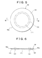
- Fig. 5 is a plan view of a plate material for explaining a method of manufacturing a carrier according to the invention.
- Fig. 6 is a cross-sectional view taken along a line VI-VI shown in Fig. 5.
- Fig. 7 is a plan view of a state where a pilot hole and engagement holes are made in one pre-flange of the plate material shown in Fig. 5 and where auxiliary openings and reference holes are made in pre-joints of the plate material shown in Fig. 5.
- Fig. 8 is a cross-sectional view taken along a line VIII-VIII shown in Fig. 7.
- Fig. 9 is a plan view of a state where the engagement holes in the plate material shown in Fig. 7 are chamfered.
- Fig. 10 is a cross-sectional view taken along a line X-X shown in Fig. 9.
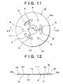
- Fig. 11 is a plan view of a state where the pilot holes in the plate material shown in Fig. 9 are formed into through-holes and where the engagement holes in the plate material shown in Fig. 9 are finished to a dimension allowing engagement with rotational shafts of rotating bodies.
- Fig. 12 is a cross-sectional view taken along a line XII-XII shown in Fig. 11.
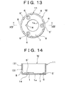
- Fig. 13 is a plan view of a cup-shaped material that has been formed by bending and drawing the plate material shown in Fig. 11.
- Fig. 14 is a cross-sectional view taken along a line XIV-XIV shown in Fig. 13.
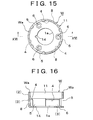
- Fig. 15 is a plan view of a state where a groove designed as a bending guide is formed on the border between pre-joints and the other pre-flange on the inner periphery of a wall of the cup-shaped material shown in Fig. 13.
- Fig. 16 is a cross-sectional view taken along a line XVI-XVI shown in Fig. 15.
- Fig. 17 is a plan view of a state where front-end openings in the wall of the cup-shaped material shown in Fig. 15 are preliminarily closed off at an appropriate angle from the groove so that the front-end openings are slightly shrunk radially inwardly.
- Fig. 18 is a cross-sectional view taken along a line XVIII-XVIII shown in Fig. 17.
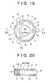
- Fig. 19 is a plan view of a state where mandrels are inserted through the openings preliminarily closed off as shown in Fig. 17 so that the front-end openings in the wall are shrunk radially inwardly.
- Fig. 20 is a cross-sectional view taken along a line IIX-IIX shown in Fig. 19.
- Fig. 21 is a plan view of a state where engagement holes are made in the other flange of the material shown in Fig. 19.
- Fig. 22 is a cross-sectional view taken along a line IIXII-IIXII shown in Fig. 21.
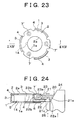
- Fig. 23 is a plan view of a state where the engagement holes shown in Fig. 21 are chamfered.
- Fig. 24 is a cross-sectional view which is taken along a line IIXIV-IIXIV shown in Fig. 23 and which also shows a chamfering machine according to one embodiment of the invention.
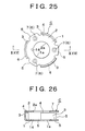
- Fig. 25 is a plan view of a state where the engagement holes chamfered as shown in Fig. 23 are finished to a dimension allowing engagement with rotational shafts of rotating bodies.
- Fig. 26 is a cross-sectional view taken along a line IIXVI-IIXVI shown in Fig. 25.
- Fig. 27 is a plan view of a state where mandrels are inserted from openings made in the joints of the carrier shown in Fig. 25 through positions for mounting rotating bodies between both the flanges and where both the flanges are swaged towards the mandrels.
- Fig. 28 is a cross-sectional view taken along a line IIXVIII-IIXVIII shown in Fig. 27.
- Fig. 29 is a cross-sectional view of a pressing machine according to one embodiment of the invention in a state where the preliminarily closed-off material is being closed off.
- Fig. 30 is a cross-sectional view of a pressing machine according to one embodiment of the invention in a state where the material shown in Fig. 29 has been closed off.
- Fig. 31 is a cross-sectional view of a method of manufacturing a carrier according to a second embodiment of the invention.
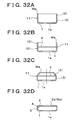
- Fig. 32 is a cross-sectional view of a method of manufacturing a carrier according to a third embodiment of the invention.
- Fig. 33 is a cross-sectional view of a method of manufacturing a carrier according to a fourth embodiment of the invention.
- Fig. 34 is a cross-sectional view of a method of manufacturing a carrier according to a fifth embodiment of the invention.
- Fig. 35 is a cross-sectional view of a method of manufacturing a carrier according to a sixth embodiment of the invention.
- Fig. 36 is a cross-sectional view of a method of manufacturing a carrier according to a seventh embodiment of the invention.
- Fig. 37 is a cross-sectional view of a method of manufacturing a carrier according to an eighth embodiment of the invention.
- Fig. 38 is a cross-sectional view of a method of manufacturing a carrier according to a ninth embodiment of the invention.
- Fig. 39 is a cross-sectional view of a carrier according to the related art.
- a carrier according to one embodiment of the invention will be described in detail with reference to Figs. 1, 2, which show a carrier C for rotatably supporting planetary gears (not shown) as rotating bodies in a planetary gear unit of an automatic transmission employed in an automobile and the like as described above.
- like reference numerals denote like or similar components.
- the carrier C of the invention is integrally formed of a pair of flanges 1, 2 and a plurality of joints 3 through plastic deformation of a single material.
- the flanges 1, 2 are opposed to each other and rotatably support rotating bodies therebetween.
- the joints 3 connect both the flanges 1, 2.
- a groove 4 is formed on the border between the flanges 1, 2 and the joints 3.
- the carrier C has openings 5 for exposing planetary gears so that the planetary gears and the like are inserted into the carrier C among the joints 3 and that the planetary gears can engage ring gears (not shown).
- Engagement holes 6, 7 for rotatably supporting rotational shafts of rotating bodies are made in the flanges 1, 2 of the carrier C respectively.
- Each of the flanges 1, 2, which constitute a pair, is formed generally in the shape of a disc.
- through-holes la, 2a through which shafts (not shown) and sun gears (not shown) are inserted, are made at the centers of the flanges 1, 2 respectively.
- the flanges 1, 2 of the invention function substantially in the same manner as the carrier plate 31 and the base plate 32 of the carrier C' of the aforementioned related art.
- a plurality of joints 3 are formed along outer peripheral edges of the flanges 1, 2 in the direction parallel to an axis J-J so as to retain opposed faces of the flanges 1, 2 at a predetermined distance.
- joints 3 of the invention function substantially in the same manner as a plurality of columns 33 protruding towards the base plate 32 substantially in the direction parallel to the shafts from the outer periphery of the plate portion 3a of the carrier plate 31 of the carrier C' of the aforementioned related arts.
- the flanges 1, 2 respectively have the three engagement holes 6, 7 for engagement with rotational shafts (not shown) for rotatably supporting planetary gears.
- the three joints 3 are disposed along the outer peripheral edges of the flanges 1, 2 substantially at the centers with respect to the circumferential direction of the engagement holes 6, 7.
- reference holes 8 used as a positioning reference or the like are made in the joints 3 of the carrier C of this embodiment substantially at the centers with respect to the axial direction and the circumferential direction of the joints 3.
- the carrier C having such a structure can be formed through plastic deformation of a single material, for example, by spinning or drawing a plate material W using a tool such as a spatula or a press roller. Because the thus-formed carrier C is integrally formed of the flanges 1, 2 and the joints 3 with uninterrupted flow of a material, it is possible to reduce the number of parts and form the carrier C with a reduced number of processes, namely, without the necessity of performing assembling and bonding processes. Furthermore, the parallel precision of the opposed faces of the flanges 1, 2 can be enhanced at a low cost. Because the carrier demonstrates high rigidity, it is possible to reduce the thickness of the carrier and thus realize a structure allowing the weight saving of the carrier.
- the groove 4 is preliminarily formed in a portion which is to be the inside of the carrier and which is to be a border between the joints 3 and at least one of the flanges 1, 2 of the material W either along the entire circumference or discontinuously.
- the carrier C according to the invention is not limited to this embodiment.
- the carrier C employed in the planetary gear unit or the like of the automatic transmission of the automobile as mentioned above, it is possible to integrally form a boss 9 so that it continues from the through-hole la or 2a formed at the center of at least one of the flanges 1, 2 as shown in Fig. 3 in case of necessity, and form a spline or a gear 10 in the integrally formed boss 9 as shown in Fig. 4.
- the carrier C of the invention is not necessarily employed in a planetary gear unit of an automatic transmission for an automobile or the like. That is, the carrier C according to the invention is applicable to other purposes.
- the thus-constructed carrier C of the invention eliminates the necessity to assemble the columns 33 of the carrier plate 31 with the base plate 32 as is the case with the carrier C' of the related arts (see Fig. 39).
- the parallel precision is not adversely affected by the forming tolerance or the assembling error of the carrier plate 31 and the base plate 32.
- the opposed faces of the flanges 1, 2 are formed with a high degree of parallel precision.
- the carrier C having the flanges 1, 2 and rotatably supporting rotating bodies such as planetary gears between the flanges 1, 2 is manufactured.
- the plate material W is bent and drawn into the shape of a cup, whereby the flange 1 is formed substantially at the center of the plate material W and a wall 11 (e.g. see Fig. 14) is formed on the outer periphery of the flange 1.
- a front-end opening in the wall 11 formed of an outer peripheral end face Wa of the material W is closed off, and the joints 3 and the flange 2 are integrally formed so that they continue from the flange 1.
- the front-end opening of the material W formed into the shape of a cup or a tube (described later) is "closed off", it is formed so as to be shrunk radially inwardly.
- auxiliary openings 5' e.g. see Fig. 11
- the openings 5 through which rotating bodies or the like can be inserted into the carrier C are made in pre-joints (3) of the plate material W before the plate material W is bent and drawn into the shape of a cup
- the engagement holes 6 for engagement with rotational shafts for rotatably supporting planetary gears designed as rotating bodies in the carrier C are made in at least one of pre-flanges (1).
- the bending guide 4 is formed on the border between the joints 3 and at least one of the pre-flanges (1), (2) (e.g. see Fig.
- closing-off mandrels 12 are inserted from the openings 5 made in the pre-joints (3) of the material W that has been bent and drawn into the shape of a cup (e.g. see Fig. 19).
- the outer peripheral end face Wa of the cup-shaped material W is closed off so as to be shrunk radially inwardly.
- swaging mandrels 13 are inserted into mounting positions of the rotating bodies between the flanges 1, 2 from the openings 5 made in the joints 3 of the closed-off carrier C (e.g. see Fig. 27), and the flanges 1, 2 are swaged towards the swaging mandrels 13.
- the plate material W of this embodiment is generally formed into the shape of a disc having a predetermined thickness as shown in Figs. 5, 6. As indicated by chain lines in Fig. 5, the central portion of the plate material W corresponds to the pre-flange (1), and the outer peripheral edge of the plate material W corresponds to the pre-flange (2). An annular portion located between the central portion (1) and the outer peripheral edge (2) in the radial direction corresponds to the pre-joints (3).
- a generally triangular pilot hole la' is made at the center of the pre-flange (1) of the thus-formed plate material W, and three auxiliary holes 6', which are to be the engagement holes 6, are made around the pilot hole la'.
- the auxiliary holes 6' are set in a dimension slightly smaller than a dimension allowing engagement with the rotational shafts of the planetary gears.
- the three auxiliary openings 5' are made in the pre-joints (3) radially outwardly so as to correspond to the auxiliary holes 6'.
- the three reference holes 8 are made at the centers in the circumferential direction of the auxiliary openings 5' and slightly radially outwardly of the auxiliary openings 5'.
- the radial dimension of the auxiliary openings 5' is set to almost half of the width of the joints 3 (the distance between the flanges of the carrier). Then, more processes are performed to form the openings 5 through which planetary gears or the like can be inserted into the carrier C thus manufactured.
- the plate material W is chamfered by press working, cutting operations or the like so that the peripheries of sides of the auxiliary holes 6' which are to be the inside of the carrier C are inclined with a diameter gradually increasing towards the inside of the carrier C.
- the dimension of the auxiliary holes 6' made in advance changes because of the chamfering.
- the chamfering means that the side of the auxiliary holes 6' which is to be the inside of the carrier C is scraped off.
- the plate material W is punched so that the periphery of the pilot hole la' assumes a generally circular shape, and one of the through-holes la through which shafts (not shown) and sun gears (not shown) are inserted is made.
- a notch 14 as a mark is made in the circular through-hole la for example for the purpose of detecting the rotational phase of the formed carrier C in the circumferential direction.
- the chamfered auxiliary holes 6' are finished into the engagement holes 6 having a dimension allowing engagement with the rotational shafts of the planetary gears.
- the plate material W is bent and drawn into the shape of a cup by means of pressing or the like, and the flange 1 and the wall 11 extending substantially perpendicularly to the outer periphery of the flange 1 are formed.
- the wall 11 constitutes the joints 3 and the other flange 2.
- the auxiliary openings 5' made in advance have almost half of the height of the pre-joints (3) extending from the outer peripheral edge of the flange 1 to the wall 11.
- the auxiliary openings 5 are punched on the front-end side of the wall 11 to a predetermined height and formed into the openings 5.
- the groove 4 designed as a bending guide is formed on the border between the pre-flange (2) and the pre-joints (3) on the inner periphery of the wall 11 either along the entire circumference or discontinuously.
- the wall 11 is preliminarily closed off at an appropriate angle from the groove 4 so that the front-end opening in the wall 11 (the outer peripheral end face Wa of the material W) is slightly shrunk radially inwardly.
- each of the closing-off mandrels 12 is inserted from one of the openings 5 to another one adjacent thereto so as to be close to a corresponding one of the joints 3, and pressed by a pressing machine shown in Figs. 29, 30.
- the material W is then closed off so that the front-end opening in the wall 11 (the cup-shaped opening defined by the outer peripheral end face Wa of the material W) is shrunk radially inwardly, until the pre-flange (2) becomes parallel to the flange 1.
- the pressing machine has an upper mold 40 and a lower mold 41, which are vertically movable relative to each other.
- the upper mold 40 has a punch 42, which presses the front-end opening Wa of the preliminarily closed-off material W when the upper mold 40 is relatively close to the lower mold 41.
- the lower mold 41 has a die 43 for accommodating the preliminarily closed-off material W, an ejector 44 slidably fitted into the die 43 to support the material W, and an ejector rod 45 for vertically moving the ejector 44 in the die 43.
- the inner diameter of the die 43 is approximately equal to the diameter of a bottom of the cup-shaped material W, which is to be the flange 1.
- holes are made in the die 43 so as to correspond to the openings 5 made between the joints 3 of the material W.
- the closing-off mandrels 12 can be inserted into the openings 5 in the material W through the holes (see Fig. 19).
- the height of the closing-off mandrels 12 is approximately equal to the distance between the inner faces of the flanges 1, 2 of the carrier C.
- the material W is first accommodated in the die 43 with the upper mold 40 and the lower mold 41 being spaced apart from each other, and the closing-off mandrels 12 are inserted from the openings 5.
- the punch 42 presses the front-end opening Wa of the preliminarily closed-off material W as shown in Fig. 29.
- the preliminarily closed-off material W is bent so that the front-end opening Wa of the material W is shrunk radially inwardly, until the wall 11 extends substantially at a right angle from the groove 4, namely, until the wall 11 becomes parallel to the flange 1.
- the portions among the openings 5 in the circumferential direction constitute the joints 3, and the portion (2) which substantially forms a right angle with the joints 3 and which extends parallel to the flange 1 constitutes the flange 2. That is, the foregoing processes are performed to integrally form the joints 3 and the flange 2 so that they continue from the flange 1.
- the closed-off front-end opening (the outer peripheral end face Wa) constitutes the through-hole 2a through which a shaft (not shown) or a sun gear (not shown) is inserted. At this moment, especially the front-end opening Wa of the closed-off material W generally tends to be crimpled because the material is compressed in the circumferential direction by being shrunk.
- the material W is thick enough to demonstrate rigidity for preventing especially the front-end opening Wa from being crimpled but is thin enough to sufficiently save the weight of the carrier C.
- the material W is prevented from being crimpled. Because the auxiliary openings 5' and the openings 5 are made in advance before the material W is bent and drawn, the end faces of the flanges 1, 2 facing the openings 5 are not curved so as to face each other. Because the flanges 1, 2 and the joints 3 are integrally formed with uninterrupted flow of the material W, the carrier C is formed with high rigidity.
- the flanges 1, 2 and the joints 3 can be made relatively thin, whereby it becomes possible to save the weight of the carrier C.
- auxiliary holes 7' are made in the flange 2 of the carrier C so as to correspond to the engagement holes 6 made in the flange 1.
- the auxiliary holes 7' are set in a dimension slightly smaller than a dimension allowing engagement with the rotational shafts of the planetary gears.
- the material W is chamfered so that the peripheries of sides of the auxiliary holes 7' which are to be the inside of the carrier C are inclined with a diameter gradually increasing towards the inside of the carrier C.
- the auxiliary holes 7' can be chamfered using a chamfering machine 20 as shown in Fig. 24.
- the chamfering machine 20 has a master cam member 21 inserted into the carrier C through one of the openings 5, an auxiliary cam member 22 longitudinally movably supported in the master cam member 21, and a chamfering punch 23 protruded from the master cam member 21 by the auxiliary cam member 22.
- One end face 21a of the master cam member 21 is inclined in the shape of a cam so that the chamfering punch 23 moves into the opening 5 and faces a corresponding one of the auxiliary holes 7' as a cam 24 moves vertically.
- End faces 22a, 22b of the auxiliary cam member 22 are inclined in the shape of a cam, and an insertion hole 21c is made in the master cam member 21 at the end on the side of the cam-shaped end face 21a so that a cam 25 can press the cam-shaped end face 22a of the auxiliary cam member 22.
- an end face 23a of the chamfering punch 23 located in the master cam member is inclined in the shape of a cam so as to correspond to the inclination of the end face 22b of the auxiliary cam member 22.
- the other end face 23b of the chamfering punch 23 is formed so as to correspond to a shape into which the engagement holes 7 are chamfered.
- the master cam member 21 is disposed so as to correspond to one of the openings 5 between the joints 3. If the cam-shaped end face 21a of the master cam member 21 is pressed by the cam 24 that is vertically driven by a pressing machine (not shown), the chamfering punch 23 moves so as to match a corresponding one of the unchamfered auxiliary holes 7' and the master cam member 21 is inserted into a space between the flanges 1, 2 through the opening 5 of the joints 3. At this moment, the cam-shaped end face 22a of the auxiliary cam member 22 on the side of the insertion hole 21c is not being pressed by the cam 25. Accordingly, the chamfering punch 23 is accommodated in the master cam member 21 without protruding therefrom.
- the auxiliary holes 7' After completion of the aforementioned chamfering of the auxiliary holes 7', the auxiliary holes 7' that have changed in dimension by being chamfered are finished into the engagement holes 7 having a dimension allowing engagement with the rotational shafts of the planetary gears, as shown in Figs. 25, 26.
- the swaging mandrels 13 have parallel faces which are opposed to the flanges 1, 2.
- the width (height) of the faces is set so as to substantially coincide with a desired distance between the opposed faces of the flanges 1, 2 of the carrier C.
- planetary gears are inserted into a space between the flanges 1, 2 from the openings 5, and the ends of rotational shafts of the planetary gears engage the engagement holes 6, 7 made in the flanges 1, 2 respectively.
- the planetary gears are rotatably and stably supported with their rotational shafts being supported by both the flanges 1, 2 which demonstrate a high degree of parallel precision.
- Fig. 31 shows a method of manufacturing the carrier C according to a second embodiment of the invention.
- Fig. 32 shows a third embodiment of the invention.
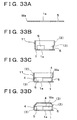
- Fig. 33 shows a fourth embodiment of the invention.
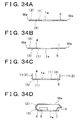
- Fig. 34 shows a fifth embodiment of the invention.
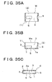
- Fig. 35 shows a sixth embodiment of the invention.
- Fig. 36 shows a seventh embodiment of the invention.
- Fig. 37 shows an eighth embodiment of the invention.
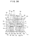
- Fig. 38 shows a ninth embodiment of the invention.
- one of the through-holes la through which a shaft (not shown) or a sun gear (not shown) is inserted, is first of all made at the center in one of pre-flanges (1) of the plate material W formed into a circular shape, and the plate material W is bent and drawn into the shape of a cup. Thereafter, as shown in Fig. 31B, the opening 5 is made in a lower portion (of the drawing) in the wall 11 of the cup-shaped material W.
- the groove 4 designed as a bending guide is formed in the inner periphery of the wall 11 of the material W on the border between the joint 3 and the other flange 2. Then, as shown in Fig.
- the outer peripheral portion of the flange 1 which faces the opening 5 is flattened.
- the material W is preliminarily closed off at an appropriate angle from the groove 4 so that the front-end opening of the wall (the outer peripheral end face Wa of the material W) is slightly shrunk radially inwardly by means of spinning or the like.
- the closing-off mandrels 12 are inserted from the openings 5 and the material W is pressed.
- the material W is then closed off so that the front-end opening in the wall 11 (the outer peripheral face Wa of the material W) is shrunk radially inwardly, until the pre-flange (2) becomes parallel to the flange 1.
- the integral-type carrier C is formed so that the joints 3 for connecting the opposed flanges 1, 2 continue therefrom.
- one of the through-holes la through which a shaft (not shown) or a sun gear (not shown) is inserted, is first of all made at the center in one of pre-flanges (1) of the plate material W formed into a circular shape, and the plate material W is bent and drawn into the shape of a cup.
- the groove 4 designed as a bending guide is formed in the inner periphery of the wall 11 of the cup-shaped material W in a portion which is to be the border between the joints 3 and the flange 2. Then, as shown in Fig.
- the material W is preliminarily closed off at an appropriate angle from the groove 4 so that the front-end opening in the wall 11 is slightly shrunk radially inwardly by means of spinning or the like. Then, as shown in Fig. 32D, the material W is closed off so that the front-end opening in the wall 11 (the outer peripheral face Wa of the material W) is shrunk radially inwardly, and the integral-type carrier C is formed so that the joints 3 for connecting the opposed flanges 1, 2 continue therefrom. The openings 5 are thereafter made in the joints 3 (not shown).
- one of the through-holes la through which a shaft (not shown) or a sun gear (not shown) is inserted, is first of all made at the center in one of pre-flanges (1) of the plate material W formed into the shape of a disc, and the openings 5 are made around the through-hole la. Thereafter, the plate material W is bent and drawn into the shape of a cup as shown in Fig. 33B, and the groove 4 designed as a bending guide is formed in the inner periphery of the wall 11 of the cup-shaped material W in a portion which is to be the border between the joints 3 and the flange 2. Then, as shown in Fig.
- the material W is preliminarily closed off at an appropriate angle from the groove 4 so that the front-end opening in the wall 11 is slightly shrunk radially inwardly by means of spinning or the like, and the material W is then closed off so that the front-end opening in the wall 11 (the outer peripheral end face Wa of the material W) is shrunk radially inwardly.
- the carrier C is integrally formed so that the joints 3 for connecting the opposed flanges 1, 2 continue therefrom, as in the aforementioned embodiments.
- one of the through-holes la through which a shaft (not shown) or a sun gear (not shown) is inserted, is first of all made at the center in one of pre-flanges (1) of the plate material W formed into the shape of a disc, and the openings 5 are made around the through-hole la.
- the groove 4 designed as a bending guide is formed in the inner periphery of the wall 11 of the plate material W in a portion which is to be the border between the joints 3 and the flange 2.
- Fig. 34A one of the through-holes la, through which a shaft (not shown) or a sun gear (not shown) is inserted, is first of all made at the center in one of pre-flanges (1) of the plate material W formed into the shape of a disc, and the openings 5 are made around the through-hole la.
- the groove 4 designed as a bending guide is formed in the inner periphery of the wall 11 of the plate material W in a portion which is to be the border between the joints 3 and the
- the plate material W is bent from the groove 4 and drawn into the shape of a cup. That is, as long as the bending guide 4 of the invention is formed before the material W is closed off, the bending guide 4 may be formed before the plate material W is bent and drawn into the shape of a cup.
- the wall 11 formed by bending and drawing the material W constitutes only the flange 2.
- the material W is closed off so that the front-end opening in the wall 11 (the outer peripheral end face Wa of the material W) is shrunk radially inwardly.
- the integral-type carrier C is formed so that the joints 3 for connecting the opposed flanges 1, 2 continue therefrom.
- a tubular material W is prepared in the sixth embodiment.
- the openings 5 are first of all made at the axial centers in the tubular material W.
- the tubular material W is formed into the shape of a cup by closing off one end thereof as shown in Fig. 35B.
- the other end Wa of the material W which is a cup-shaped opening, is closed off, whereby the opposed flanges 1, 2 and the joints for connecting them are integrally formed.
- both the ends of the tubular material W are sequentially closed off, they are preliminarily closed off as described above.
- the openings 5 may not necessarily be made at the outset.
- the openings 5 may also be made after one or the other end of the tubular material W has been closed off.
- a groove designed as a bending guide is formed in the inner periphery of the material W in a portion which is to be the border between the joints 3 and the flange 2.
- the groove may also be formed in the inner periphery of the tubular material W in a portion which is to be the border between the flange 1 and the joints 3 before the material W is formed into the shape of a cup by closing off one end thereof to form the flange 1.
- the auxiliary holes 6', 7' which are to be the engagement holes 6, 7 for engagement with rotational shafts of planetary gears, may be made in advance in the tubular material W.
- the tubular material W with the openings 5 made in its axial centers is prepared as shown in Fig. 36A.
- the seventh embodiment is different from the sixth embodiment in that both the ends Wa of the tubular material W are closed off simultaneously. That is, as shown in Fig. 36B, both the ends Wa of the tubular material W are preliminarily closed off at the same time. Furthermore, as shown in Fig. 36C, both the ends Wa are closed off simultaneously, whereby the opposed flanges 1, 2 are formed.
- the axial centers of the tubular material W, which are not closed off, constitute the joints 3 for integrally connecting the flanges 1, 2.
- a rod material W is prepared as shown in Fig. 37A.
- the rod material means a material which has a predetermined length (predetermined thickness) L in the axial direction of the carrier so as to be formed into the shape of a cup by backward extrusion or the like and which is thicker than the aforementioned plate material.
- the rod material W is first of all formed into the shape of a cup by backward extrusion or the like. Thereafter, as shown in Fig. 37C, one of the through-holes la, through which a shaft (not shown) or a sun gear (not shown) is inserted, is made in the bottom of the cup-shaped material W.
- the cup-shaped opening Wa is then closed off, whereby the opposed flanges 1, 2 and the joints 3 for connecting them are integrally formed as shown in Fig. 37D.
- the openings 5 among the joints 3 and the like can be made after the rod material W has been formed into the shape of a cup.
- the joints 3 are formed by bulging the axial centers of the tubular material W radially outwardly, and accordingly, the flanges 1, 2 are integrally formed so as to be opposed to each other and extend from the joints 3 radially inwardly.
- Fig. 38 shows a mechanical bulging machine for bulging the tubular material. In Fig. 38, while the material has not been bulged on the left side with respect to a center line indicated by a chain line, the material has been bulged on the right side with respect to the center line.
- This bulging machine has an upper mold 50 and a lower mold 51 which are vertically movable relative to each other, punches 52 for pressing the tubular material W so as to bulge its axial centers, and a cam mechanism 53 for driving the punches 52 radially outwardly.
- the upper mold 50 is supported by a vertical-drive rod 54 so that the upper mold 50 vertically moves relative to the lower mold 51.
- Receptacles 50a, 51a for receiving the tubular material W and cavities 50b, 51b for determining the configuration of the bulged material are formed in a butt face which is formed when the upper mold 50 and the lower mold 51 are closed.
- the punches 52 are divided in the radial direction of the material W and radially slidably supported by punch plates 55 disposed inwardly of the receptacle 50a of the upper mold 50.
- a punch holder 56 is disposed below the punches 52.
- a receptacle 57 which receives the punch holder 56 when the upper mold 50 and the lower mold 51 are butted against each other, is formed inwardly of the receptacle 51a of the lower mold 51.
- a stopper 52a protrudes from a radially intermediate position on the lower surface of each of the punches 52. Stoppers 56a, 56b are formed at radially inner and outer positions on the upper surface of the punch holder 56.
- a spring 58 is interposed between the stopper 52a of each of the punches 52 and the radially outer stopper 56a of the punch holder 56 so as to urge each of the punches 52 to retract radially inwardly.
- the cam mechanism 53 drives each of the punches 52 radially outwardly against the urging force of the spring 58 and is composed of a cam face 52b formed radially inwardly of each of the punches 52 and a cam member 59 bonded to the cam face 52b.
- the upper end of the cam member 59 is connected to a drive plate 60.
- the vertical-drive rod 54 is inserted through the drive plate 60 so as to vertically drive the drive plate 60 relative to the upper mold 50.
- both the axial ends of the tubular material W constitute a pair of the opposed flanges 1, 2.
- the through-holes la, 2a, through which shafts (not shown) and sun gears (not shown) are inserted, are defined by both the end faces Wa of the tubular material W.
- the holes 5' which are to be the openings 5, are made in advance in the axial centers of the tubular material W.
- the dimension of the holes 5' is set in accordance with the dimension of the openings 5.
- the invention is not limited to the aforementioned embodiments. It is possible to employ a hydraulic bulging machine (not shown) instead of the mechanical one. In this case, a working fluid is supplied into a tubular material at a predetermined pressure. Therefore, the tubular material is sealed to prevent the working fluid from leaking out from the holes which are made in advance in the axial centers of the tubular material and which are to be the openings 5. Alternatively, the holes which are to be the openings 5 are not made in advance in the tubular material, and the openings 5 are made in the material after it has been bulged.
Landscapes
- Engineering & Computer Science (AREA)
- General Engineering & Computer Science (AREA)
- Mechanical Engineering (AREA)
- General Details Of Gearings (AREA)
- Retarders (AREA)
- Shaping Metal By Deep-Drawing, Or The Like (AREA)
- Fittings On The Vehicle Exterior For Carrying Loads, And Devices For Holding Or Mounting Articles (AREA)
Applications Claiming Priority (4)
| Application Number | Priority Date | Filing Date | Title |
|---|---|---|---|
| JP2000038561 | 2000-02-16 | ||
| JP2000038561 | 2000-02-16 | ||
| JP2000365175A JP3826995B2 (ja) | 2000-02-16 | 2000-11-30 | キャリヤの製造方法 |
| JP2000365175 | 2000-11-30 |
Publications (3)
| Publication Number | Publication Date |
|---|---|
| EP1146254A2 true EP1146254A2 (fr) | 2001-10-17 |
| EP1146254A3 EP1146254A3 (fr) | 2002-07-10 |
| EP1146254B1 EP1146254B1 (fr) | 2005-04-13 |
Family
ID=26585501
Family Applications (1)
| Application Number | Title | Priority Date | Filing Date |
|---|---|---|---|
| EP01103100A Expired - Lifetime EP1146254B1 (fr) | 2000-02-16 | 2001-02-09 | Porte-satellite et son procédé de fabrication |
Country Status (6)
| Country | Link |
|---|---|
| US (2) | US20010018381A1 (fr) |
| EP (1) | EP1146254B1 (fr) |
| JP (1) | JP3826995B2 (fr) |
| KR (1) | KR100413263B1 (fr) |
| CN (1) | CN1252402C (fr) |
| DE (1) | DE60109978T2 (fr) |
Cited By (1)
| Publication number | Priority date | Publication date | Assignee | Title |
|---|---|---|---|---|
| DE112009000602B4 (de) * | 2008-03-11 | 2013-01-17 | Toyota Jidosha K.K. | Trägeranordnung zum Tragen von Planetenrädern |
Families Citing this family (34)
| Publication number | Priority date | Publication date | Assignee | Title |
|---|---|---|---|---|
| CA2445493A1 (fr) * | 2002-03-05 | 2003-09-18 | Metal Forming & Coining Corporation | Support de pignon destine a un engrenage planetaire et procede de fabrication d'un tel support |
| JP4103842B2 (ja) * | 2004-04-15 | 2008-06-18 | トヨタ自動車株式会社 | ラビニオ型プラネタリキャリア及びその製造方法 |
| JPWO2007026756A1 (ja) * | 2005-08-31 | 2009-03-12 | アイシン・エィ・ダブリュ株式会社 | 環状部材の製造方法および脚付き環状部材 |
| US20070197340A1 (en) * | 2006-02-17 | 2007-08-23 | Kim Young S | Internal ring gear with integral hub portion and method of manufacture |
| JP2007327608A (ja) * | 2006-06-09 | 2007-12-20 | Unipres Corp | 遊星歯車機構用キャリア組立方法 |
| US8500801B2 (en) | 2009-04-21 | 2013-08-06 | Medtronic, Inc. | Stents for prosthetic heart valves and methods of making same |
| US8202195B2 (en) * | 2009-05-06 | 2012-06-19 | GM Global Technology Operations LLC | Pinion gear subassembly and method of assembling a planet carrier assembly |
| JP5039809B2 (ja) * | 2010-04-20 | 2012-10-03 | ジヤトコ株式会社 | キャリア及びその製造方法 |
| DE102010028280B4 (de) * | 2010-04-28 | 2020-11-12 | Zf Friedrichshafen Ag | Verfahren zur Herstellung von Stanzteilen sowie Vorrichtung und Verwendung |
| JP5401519B2 (ja) * | 2010-11-18 | 2014-01-29 | ジヤトコ株式会社 | キャリア及びその製造方法 |
| JP5401435B2 (ja) * | 2010-11-18 | 2014-01-29 | ジヤトコ株式会社 | キャリア及びその製造方法 |
| DE102011004192A1 (de) * | 2011-02-16 | 2012-08-16 | Schaeffler Technologies Gmbh & Co. Kg | Planetenradträger |
| CN102954200B (zh) * | 2011-08-22 | 2015-08-26 | 张家港市九鼎机械有限公司 | 一种行星架输出轴机构及其加工工艺 |
| JP5476526B2 (ja) * | 2011-09-29 | 2014-04-23 | ジヤトコ株式会社 | キャリアの製造方法 |
| DE102012203937A1 (de) | 2012-03-14 | 2013-09-19 | Zf Friedrichshafen Ag | Planetenträger sowie Planetengetriebe mit Ringsegmenten |
| DE102012213116B4 (de) * | 2012-07-26 | 2018-10-31 | Zf Friedrichshafen Ag | Planetenradträger und Verfahren zum Herstellen eines Planetenradträgers |
| CN103836171A (zh) * | 2012-11-28 | 2014-06-04 | 江苏威鹰机械有限公司 | 自动变速器行星齿轮架组件 |
| DE102013225987B3 (de) * | 2013-12-16 | 2015-08-06 | MTU Aero Engines AG | Verfahren zur Herstellung eines zylinderförmigen Bauteils, Gehäuse und Strömungsmaschine |
| DE102014214382B3 (de) * | 2014-07-23 | 2015-11-12 | Schaeffler Technologies AG & Co. KG | Einteiliger Planetenträger im Einteil-Doppelflanschdesign |
| WO2016086931A1 (fr) * | 2014-12-03 | 2016-06-09 | Schaeffler Technologies AG & Co. KG | Entraînement à satellites pourvu d'un porte-satellites |
| DE102015213725A1 (de) | 2015-07-21 | 2017-01-26 | Schaeffler Technologies AG & Co. KG | Aus Segmenten zusammengesetzter Planetenträger |
| DE102015213723A1 (de) | 2015-07-21 | 2017-01-26 | Schaeffler Technologies AG & Co. KG | Gefaltete Verbindungsstege für Planetenträger |
| DE102015214110A1 (de) | 2015-07-27 | 2017-02-02 | Schaeffler Technologies AG & Co. KG | Zusammengesetzter Planetenträger |
| DE102016210526B4 (de) * | 2016-06-14 | 2023-06-15 | Schaeffler Technologies AG & Co. KG | Planetenradgetriebebolzen mit endseitiger Montagemarkierung und Verfahren zum Herstellen eines Planetenradgetriebebolzens |
| DE102017117954A1 (de) | 2017-08-08 | 2019-02-14 | Schaeffler Technologies AG & Co. KG | Planetenträger für ein Planetengetriebe |
| US11092233B2 (en) * | 2017-09-05 | 2021-08-17 | Aisin Aw Co., Ltd. | Planetary carrier and method for manufacturing the same |
| NL2019488B1 (en) * | 2017-09-06 | 2019-03-14 | Punch Powertrain Nv | Improved planet carrier. |
| GB201819768D0 (en) * | 2018-12-04 | 2019-01-23 | Rolls Royce Plc | A method of manufacturing a planet carrier of a gearbox |
| CN109759781A (zh) * | 2018-12-20 | 2019-05-17 | 佛山市罗斯特传动设备有限公司 | 一种精密行星减速机行星架的加工及检测方法 |
| US11878133B2 (en) | 2019-10-08 | 2024-01-23 | Medtronic, Inc. | Methods of preparing balloon expandable catheters for cardiac and vascular interventions |
| JP7382905B2 (ja) * | 2020-06-26 | 2023-11-17 | 株式会社クボタ | 遊星ギヤ装置 |
| JP7349962B2 (ja) * | 2020-06-26 | 2023-09-25 | 株式会社クボタ | 複合遊星ギヤ装置 |
| CN112958737A (zh) * | 2021-03-23 | 2021-06-15 | 江苏威鹰机械有限公司 | 一种新能源轿车行星支架锻件及其生产工艺 |
| JP2023179256A (ja) * | 2022-06-07 | 2023-12-19 | 株式会社オリジン | 接合部品、接合部品の製造方法及び接合部品の製造装置 |
Citations (1)
| Publication number | Priority date | Publication date | Assignee | Title |
|---|---|---|---|---|
| JPH10288248A (ja) | 1997-04-15 | 1998-10-27 | Nissan Motor Co Ltd | 自動変速機の遊星歯車装置 |
Family Cites Families (25)
| Publication number | Priority date | Publication date | Assignee | Title |
|---|---|---|---|---|
| US1931163A (en) * | 1930-06-16 | 1933-10-17 | Cleveland Welding Co | Method of making hub shells and like tubular metal articles |
| US2123842A (en) * | 1936-05-06 | 1938-07-12 | United Carr Fastener Corp | Method of making bag frames |
| US2684103A (en) * | 1948-08-07 | 1954-07-20 | Serrick Corp | Metalworking apparatus |
| US3046064A (en) * | 1958-08-06 | 1962-07-24 | Schaeffler Ohg Industriewerk | Needle bearings |
| US3842481A (en) * | 1970-05-15 | 1974-10-22 | Borg Warner Ltd | Method of making planetary carrier assembly |
| JPS5086469A (fr) | 1973-12-06 | 1975-07-11 | ||
| DE2503518A1 (de) * | 1975-01-29 | 1976-08-19 | Zahnradfabrik Friedrichshafen | Planetenradtraeger aus blechteilen |
| DE2605230C2 (de) * | 1976-02-11 | 1978-04-06 | Zahnradfabrik Friedrichshafen Ag, 7990 Friedrichshafen | Planetenradträger |
| GB1573175A (en) | 1976-02-11 | 1980-08-20 | Zahnradfabrik Friedrichshafen | Planet wheel carrier |
| JPS53134160A (en) * | 1977-04-28 | 1978-11-22 | Toyota Motor Corp | Gearing device in automatic transmission gear box for automobile |
| JPS5772728A (en) | 1980-10-27 | 1982-05-07 | Shigenobu Watari | Bending method for thick metallic plate |
| JPS58156773A (ja) | 1982-03-10 | 1983-09-17 | Nissan Motor Co Ltd | 遊星歯車キヤリア組立体 |
| JPS59126136A (ja) | 1982-12-29 | 1984-07-20 | Aisin Warner Ltd | 遊星歯車機構のキヤリヤカバ−とハブの結合構造 |
| JPS6046819A (ja) | 1983-08-23 | 1985-03-13 | Eidai Co Ltd | 金属板の折曲方法 |
| FR2606848B1 (fr) | 1986-11-18 | 1989-03-10 | Mecanique Gle Atel | Porte-satellites |
| JPH0796128B2 (ja) | 1987-11-06 | 1995-10-18 | 日新製鋼株式会社 | 複合型制振鋼板のv曲げ加工方法 |
| JPH0281949U (fr) | 1988-12-14 | 1990-06-25 | ||
| DE4138548C1 (fr) * | 1991-11-23 | 1993-03-18 | Mercedes-Benz Aktiengesellschaft, 7000 Stuttgart, De | |
| JPH07133848A (ja) | 1993-11-09 | 1995-05-23 | Aisin Aw Co Ltd | 自動変速機用キャリア組立体 |
| JP3221639B2 (ja) | 1994-01-14 | 2001-10-22 | ヒーハイスト精工株式会社 | フランジ付リニアボールベアリングの成型方法 |
| DE4421931A1 (de) * | 1994-06-23 | 1996-01-11 | Ford Werke Ag | Planetenradträger |
| US5470286A (en) * | 1994-07-29 | 1995-11-28 | General Motors Corporation | Reaction carrier assembly having zero relative pin deflection |
| JP3693445B2 (ja) * | 1997-02-10 | 2005-09-07 | 日本精工株式会社 | 自在継手用ヨークとその製造方法 |
| DE29810270U1 (de) * | 1998-06-09 | 1998-08-06 | sicht pack Hagner GmbH, 72280 Dornstetten | Abdeckung von Fahrzeugrädern mit Leichtmetallfelgen |
| CA2323895A1 (fr) * | 2000-10-18 | 2002-04-18 | Chiu, Yen-Chun | Assemblage de moyeu de roue excentrique reglable |
-
2000
- 2000-11-30 JP JP2000365175A patent/JP3826995B2/ja not_active Expired - Fee Related
-
2001
- 2001-02-09 EP EP01103100A patent/EP1146254B1/fr not_active Expired - Lifetime
- 2001-02-09 DE DE60109978T patent/DE60109978T2/de not_active Expired - Lifetime
- 2001-02-15 KR KR10-2001-0007505A patent/KR100413263B1/ko not_active Expired - Fee Related
- 2001-02-16 US US09/783,992 patent/US20010018381A1/en not_active Abandoned
- 2001-02-16 CN CNB011108533A patent/CN1252402C/zh not_active Expired - Fee Related
-
2003
- 2003-10-22 US US10/689,613 patent/US7100416B2/en not_active Expired - Fee Related
Patent Citations (1)
| Publication number | Priority date | Publication date | Assignee | Title |
|---|---|---|---|---|
| JPH10288248A (ja) | 1997-04-15 | 1998-10-27 | Nissan Motor Co Ltd | 自動変速機の遊星歯車装置 |
Cited By (1)
| Publication number | Priority date | Publication date | Assignee | Title |
|---|---|---|---|---|
| DE112009000602B4 (de) * | 2008-03-11 | 2013-01-17 | Toyota Jidosha K.K. | Trägeranordnung zum Tragen von Planetenrädern |
Also Published As
| Publication number | Publication date |
|---|---|
| US20040082432A1 (en) | 2004-04-29 |
| DE60109978T2 (de) | 2006-02-23 |
| KR100413263B1 (ko) | 2003-12-31 |
| CN1309039A (zh) | 2001-08-22 |
| JP3826995B2 (ja) | 2006-09-27 |
| KR20010082655A (ko) | 2001-08-30 |
| CN1252402C (zh) | 2006-04-19 |
| US20010018381A1 (en) | 2001-08-30 |
| DE60109978D1 (de) | 2005-05-19 |
| JP2001343064A (ja) | 2001-12-14 |
| US7100416B2 (en) | 2006-09-05 |
| EP1146254B1 (fr) | 2005-04-13 |
| EP1146254A3 (fr) | 2002-07-10 |
Similar Documents
| Publication | Publication Date | Title |
|---|---|---|
| EP1146254B1 (fr) | Porte-satellite et son procédé de fabrication | |
| JP2004347107A (ja) | 遊星ギヤ用キャリア | |
| EP0763673A2 (fr) | Volant à deux masses | |
| US20250083210A1 (en) | Method of forming a splined component | |
| US7448298B2 (en) | Viscous damper | |
| KR100657208B1 (ko) | 스플라인홈을 가지는 원통부재의 제조방법 및스플라인홈을 가지는 원통부재 | |
| JP2008264821A (ja) | クラッチ用プーリの製造方法 | |
| JP3484321B2 (ja) | 自動車用トランスミッションにおけるトルク伝達部材,スプライン歯形の成形方法およびスプライン歯形成形装置 | |
| US6959576B2 (en) | Cold forming of splined transmission hubs | |
| US8523731B2 (en) | Welded component, in particular planet wheel carrier, method for producing the component and apparatus for carrying out the method | |
| JP3585743B2 (ja) | 鑞付け接合焼結部品及び同部品の製造方法 | |
| EP4053426B1 (fr) | Procede de fabrication d'un porte-disques d'embrayage et systeme d'embrayage comprenant un tel porte-disques | |
| JP4107793B2 (ja) | 歯車成形方法及びその装置 | |
| EP2030702A2 (fr) | Structure d' aube pour convertisseur de couple et son procédé de production | |
| JPH04151071A (ja) | 自動変速機用回転伝達部材の結合構造 | |
| JP3722795B2 (ja) | 車両用ドライブプレート | |
| JP3623665B2 (ja) | 内歯付きドラム | |
| JP4257742B2 (ja) | ドラム形部品の製造方法 | |
| KR20000076312A (ko) | 가동 피지지 요소의 주기적인 작동을 위한 캠 샤프트 및 이 캠 샤프트의 제조 방법 | |
| JP2007160360A (ja) | 駆動部品の塑性結合方法 | |
| JP2001232435A (ja) | 堰付クラッチハブの製造方法 | |
| JP2007185670A (ja) | 駆動部品の塑性結合方法 |
Legal Events
| Date | Code | Title | Description |
|---|---|---|---|
| PUAI | Public reference made under article 153(3) epc to a published international application that has entered the european phase |
Free format text: ORIGINAL CODE: 0009012 |
|
| 17P | Request for examination filed |
Effective date: 20010209 |
|
| AK | Designated contracting states |
Kind code of ref document: A2 Designated state(s): AT BE CH CY DE DK ES FI FR GB GR IE IT LI LU MC NL PT SE TR |
|
| AX | Request for extension of the european patent |
Free format text: AL;LT;LV;MK;RO;SI |
|
| PUAL | Search report despatched |
Free format text: ORIGINAL CODE: 0009013 |
|
| RIC1 | Information provided on ipc code assigned before grant |
Free format text: 7F 16H 57/08 A |
|
| AK | Designated contracting states |
Kind code of ref document: A3 Designated state(s): AT BE CH CY DE DK ES FI FR GB GR IE IT LI LU MC NL PT SE TR |
|
| AX | Request for extension of the european patent |
Free format text: AL;LT;LV;MK;RO;SI |
|
| AKX | Designation fees paid |
Designated state(s): DE FR GB |
|
| 17Q | First examination report despatched |
Effective date: 20030414 |
|
| GRAP | Despatch of communication of intention to grant a patent |
Free format text: ORIGINAL CODE: EPIDOSNIGR1 |
|
| GRAS | Grant fee paid |
Free format text: ORIGINAL CODE: EPIDOSNIGR3 |
|
| GRAA | (expected) grant |
Free format text: ORIGINAL CODE: 0009210 |
|
| AK | Designated contracting states |
Kind code of ref document: B1 Designated state(s): DE FR GB |
|
| REG | Reference to a national code |
Ref country code: GB Ref legal event code: FG4D |
|
| RIN1 | Information on inventor provided before grant (corrected) |
Inventor name: MATSUNAGA, KEIICHI Inventor name: TAKASHI, SUZUMURA |
|
| REG | Reference to a national code |
Ref country code: IE Ref legal event code: FG4D |
|
| REF | Corresponds to: |
Ref document number: 60109978 Country of ref document: DE Date of ref document: 20050519 Kind code of ref document: P |
|
| ET | Fr: translation filed | ||
| PLBE | No opposition filed within time limit |
Free format text: ORIGINAL CODE: 0009261 |
|
| STAA | Information on the status of an ep patent application or granted ep patent |
Free format text: STATUS: NO OPPOSITION FILED WITHIN TIME LIMIT |
|
| 26N | No opposition filed |
Effective date: 20060116 |
|
| PGFP | Annual fee paid to national office [announced via postgrant information from national office to epo] |
Ref country code: DE Payment date: 20130206 Year of fee payment: 13 Ref country code: GB Payment date: 20130207 Year of fee payment: 13 Ref country code: FR Payment date: 20130301 Year of fee payment: 13 |
|
| REG | Reference to a national code |
Ref country code: DE Ref legal event code: R119 Ref document number: 60109978 Country of ref document: DE |
|
| GBPC | Gb: european patent ceased through non-payment of renewal fee |
Effective date: 20140209 |
|
| REG | Reference to a national code |
Ref country code: FR Ref legal event code: ST Effective date: 20141031 |
|
| REG | Reference to a national code |
Ref country code: DE Ref legal event code: R119 Ref document number: 60109978 Country of ref document: DE Effective date: 20140902 |
|
| PG25 | Lapsed in a contracting state [announced via postgrant information from national office to epo] |
Ref country code: DE Free format text: LAPSE BECAUSE OF NON-PAYMENT OF DUE FEES Effective date: 20140902 Ref country code: GB Free format text: LAPSE BECAUSE OF NON-PAYMENT OF DUE FEES Effective date: 20140209 Ref country code: FR Free format text: LAPSE BECAUSE OF NON-PAYMENT OF DUE FEES Effective date: 20140228 |