EP1146511A2 - Bandtransportgerät - Google Patents
Bandtransportgerät Download PDFInfo
- Publication number
- EP1146511A2 EP1146511A2 EP01303480A EP01303480A EP1146511A2 EP 1146511 A2 EP1146511 A2 EP 1146511A2 EP 01303480 A EP01303480 A EP 01303480A EP 01303480 A EP01303480 A EP 01303480A EP 1146511 A2 EP1146511 A2 EP 1146511A2
- Authority
- EP
- European Patent Office
- Prior art keywords
- tape
- drive motor
- running
- rotation number
- load
- Prior art date
- Legal status (The legal status is an assumption and is not a legal conclusion. Google has not performed a legal analysis and makes no representation as to the accuracy of the status listed.)
- Withdrawn
Links
Images

Classifications
-
- G—PHYSICS
- G11—INFORMATION STORAGE
- G11B—INFORMATION STORAGE BASED ON RELATIVE MOVEMENT BETWEEN RECORD CARRIER AND TRANSDUCER
- G11B15/00—Driving, starting or stopping record carriers of filamentary or web form; Driving both such record carriers and heads; Guiding such record carriers or containers therefor; Control thereof; Control of operating function
- G11B15/18—Driving; Starting; Stopping; Arrangements for control or regulation thereof
- G11B15/46—Controlling, regulating, or indicating speed
- G11B15/54—Controlling, regulating, or indicating speed by stroboscope; by tachometer
-
- G—PHYSICS
- G11—INFORMATION STORAGE
- G11B—INFORMATION STORAGE BASED ON RELATIVE MOVEMENT BETWEEN RECORD CARRIER AND TRANSDUCER
- G11B15/00—Driving, starting or stopping record carriers of filamentary or web form; Driving both such record carriers and heads; Guiding such record carriers or containers therefor; Control thereof; Control of operating function
- G11B15/18—Driving; Starting; Stopping; Arrangements for control or regulation thereof
- G11B15/46—Controlling, regulating, or indicating speed
- G11B15/48—Starting; Accelerating; Decelerating; Arrangements preventing malfunction during drive change
Definitions
- This invention relates to a tape transport apparatus for transporting a tape of a video tape recorder and the like.
- a tape When a video tape recorder is operated in a recording mode or a reproducing mode, a tape is pinched between a capstan and a pinch roller and transported at a predetermined speed by rotatably driving a capstan driven by a capstan motor. And when the video tape recorder is operated in a fast-forward running mode or a rewinding running mode, the tape is wound around a supply reel or a take-up reel by rotatably driving the supply reel or the take-up reel at a high speed by transmitting a driving power of a capstan motor by way of a transmitting mechanism such as a pulley, belt and the like connecting between the supply reel or the take-up reel and the capstan motor with the capstan and the pinch roller disengaged with each other.
- a voltage higher than that of a usual running mode such as reproducing mode is applied to the capstan motor so as to thereby rotate at a high rotation speed.
- a tape transport apparatus comprising a tape running means for running a tape, a drive means for driving said tape running means, a control means for controlling an output to be supplied to said drive means depending on a running mode, and a load detection means for detecting a load applied to the tape or the drive means, said control means reducing an output supplied to the drive means by detecting a winding load during tape winding in a fast-forward running mode or a rewinding running mode.
- the tape running means includes a supply reel, a take-up reel and a capstan which are used for running a tape
- the drive means includes a single drive motor for driving each reel and a capstan and two drive motors, one for a capstan and another for reels.
- the control means controls an output voltage applied to the drive motor and applies an output voltage higher than other running modes to transport the tape at a high speed when a fast-forward running mode or a rewinding running mode is selected.
- the load detection means is a detector of any changes in operation caused by winding load.
- a rotation detector to detect a rotation number of a drive motor, reels or a capstan may be used.
- a speed detector to detect the running speed of a tape or a detector to directly detect a load applied to the tape such as a detector to detect a tape tension or a degree of the looseness of the tape.
- the drive motor is not stopped, but the output voltage supplied to the drive motor is reduced instead, so that the drive motor is driven at a lower speedwith a drive torque sufficient to transport a tape. Consequently, the tape winding is not interrupted but successively continued without causing troubles due to the winding load.
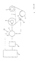
- FIG. 1 A tape transport apparatus of a video tape recorder according to one embodiment of the present invention is schematically shown in Fig. 1.
- Shown in Fig. 1 is a well-known tape transport apparatus comprising a supply reel 2 and a take-up reel 3 adapted to transport a tape 1 at a high speed by winding the tape, a capstan 5 and a pinch roller 6 adapted to transport the tape 1 at a predetermined speed by pinching therebetween the tape 1 wound around a rotary cylinder 4, and a drive motor 7 rotatably driving each of the reels 2, 3 and the capstan 5.
- a driving force of a high torque is transmitted from the drive motor 7 selectively to either of the reel 2 and the reel 3 depending on the tape running direction by means of a transmitting mechanism such as a pulley, a belt and the like, while a driving force of a low torque is transmitted to the capstan 5.
- a controller 8 adapted to control a drive mode of the drive motor 7 depending on a tape running mode of a reproducing mode, a recording mode, a fast-forward reproducing mode, a rewinding reproducing mode, a fast-forward running mode, and a rewinding running mode of a video tape recorder.
- a motor driver 9 drives the drive motor 7 at a predetermined rotation number.
- the rotation number of the drive motor 7 is detected by a rotation detector 10 such as, for example, a frequency generator (FG) generating a frequency signal proportional to the rotation number of the drive motor 7 to be supplied to the controller 8.
- the rotation detector 10 may be arranged so as to detect the rotation number of the capstan 5 driven by the drive motor 7.
- the rotation detector 10 may be arranged so as to detect the rotation number of the reels 2 and 3 which rotate synchronizing with the rotation of the capstan 5.
- the controller 8 is a microcomputer switching the direction for transmitting a drive force of the drive motor 7 in compliance with a mode inputted and controlling the output voltage supplied to the drive motor 7 so as to obtain a tape running speed in compliance with the input mode.
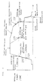
- a fast-forward running mode or a rewinding running mode the drive motor 7 is rotated at a high speed to transport the tape 1 at a high speed.
- a low voltage is supplied to the drive motor 7 until the rotation number of the drive motor 7 exceeds a first preset value, and subsequently the voltage supplied to the drive motor 7 is switched to a higher one.
- the drive motor 7 When the rotation number of the drive motor 7 reaches the maximum rotation number, the drive motor 7 is controlled so as to rotate at a predetermined constant speed maintaining the maximum rotation number.
- the running speed of the tape 1 is increasing.
- the drive motor 7 is controlled so as to maintain said running speed and the rotation number of the drive motor 7 is reduced gradually.
- the rotation number of the supply reel 2 reaches a predetermined rotation number
- the drive motor 7 is so controlled as to maintain said rotation number and the rotation number of the drive motor 7 is reduced further.
- the output voltage applied to the drive motor 7 is switched from a high voltage to a low voltage to perform a first speed reduction.
- a tape winding can be made in conformity with the winding condition of the tape 1, so that a time required for a fast-forward running or a rewinding running is reduced and a high speed winding can be attained.
- the output voltage applied to the drive motor 7 is set to be a low voltage.
- the output voltage to the drive motor 7 is increased gradually up to a low voltage (12V).
- the tape 1 starts to run slowly.
- the rotation number of the drive motor 7 exceeds the first predetermined value (1,000rpm) by the actual measurement, namely, when a FG period detected by the rotation detector 10 is under 0.166msec
- the output voltage applied to the drive motor 7 is switched from the low voltage (12V) to the high voltage (23V) and increased further.
- the running speed of the tape 1 is increased gradually.
- the controller 8 operates a timer for a fixed time, e.g. two seconds, and then a load flag is turned ON.
- the drive motor 7 is controlled so as to rotate at a predetermined constant speed maintaining the maximum rotation number and the high speed winding of the tape is performed With the tape 1 being wound, the running speed of the tape 1 gets faster. Then the rotation number of the drive motor 7 is reduced gradually so that the running speed of the tape 1 becomes constant. With the tape 1 being wound further, the rotation speed of the supply reel 2 becomes too fast. Then the rotation number of the drive motor 7 is reduced further, so that the rotation number of the supply reel 2 becomes constant.
- the rotation number of the drive motor 7 is under the predetermined value (2,000rpm)
- the output voltage supplied to the drive motor 7 is switched from a high voltage to a low voltage and a load flag is turned OFF. Then the rotation number of the drive motor 7 is reduced rapidly and the first deceleration can be performed.
- the drive motor 7 When the area of the take-up reel 3 reaches a predetermined value in conformity with the tape amount wound up around the reel, the drive motor 7 is so controlled as to reduce the rotation number and the second deceleration is performed. Subsequently, when the rotation number of the drive motor 7 is under the predetermined rotation number (500rpm), the third deceleration is performed to rotate the drive motor 7 at a lower speed. By such stepwise decelerations, the running speed of the tape 1 is reduced while maintaining a tape tension nearly constant and the rewinding of the tape 1 is stopped when a tape end is detected.
- the running tape can be decelerated in conformity with the tape end without causing a rapid deceleration.
- the tape winding can be performed maintaining the tape tension constant without causing the slack of the running tape Further, the tape rewinding can be completed without a sudden stop of the tape running, so that the tape 1 and the related mechanism can not be damaged, thus resulting in a safe tape rewinding.
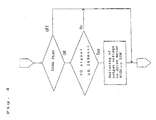
- the controller 8 monitors any changes of the rotation number of the drive motor 7 detected by the rotation detector 10 in a fast-forward running mode or a rewinding running mode.
- the drive motor 7 may have a breakdown. So, the controller 8 detects the rotation number of the drive motor 7 to thereby detect such a load applied to the drive motor.
- the controller 8 performs such a load adjustment as to reduce the output voltage applied to the drive motor 7.
- monitoring of the changes in the rotation number of the drive motor 7 is performed when the drive motor 7 rotates at a high speed under a high voltage and the load flag is turned ON.
- a predetermined time-lag is set at the time of a load detection so as to enhance the accuracy of such load detection.
- the output voltage supplied to the drive motor 7 is switched from a high voltage to a low voltage and a load flag is turned OFF. Then the drive motor 7 is being driven under a low output voltage and the tape winding is performed. During the tape rewinding, the stepwise deceleration as described above is performed to wind up the tape 1 as soon as possible.
- a predetermined rotation number for detecting a load may be divided into several stages, and an output voltage corresponding to each stage thereof may be set for switching the output voltage in conformity with the degree of a load.
- the reduction of the tape running speed is limited to the minimum and the time required for winding the tape can be shorted to a desired extent.
- the switching operation of an output voltage applied to the drive motor may be set not only to be two steps but also to be three steps or more. In such a case, a predetermined rotation number of a drive motor is set at each of the steps, and when a load is detected at any one of these steps, the output voltage is shifted to a lower voltage by one step.
- the above load adjustment operation is applicable not only to the high speed running such as the fast-forward running mode or the rewinding running mode but also to the normal speed running mode such as in the reproducing mode so as to prevent the occurrence of the elongation or breakage of the tape.
- the present invention provides a novel tape transport apparatus wherein the output voltage applied to the drive motor is reduced when a winding load is applied during tape running so as to prevent the drive motor from being applied an excessive electric current and to protect the drive motor from any damages.
- the tape running is allowed to continue so as to perform a mode under operation consecutively. Especially, even if such winding load occurs during a fast-forward running mode or a rewinding running mode, the tape winding can be performed completely to the last.
Landscapes
- Controlling Rewinding, Feeding, Winding, Or Abnormalities Of Webs (AREA)
Applications Claiming Priority (2)
| Application Number | Priority Date | Filing Date | Title |
|---|---|---|---|
| JP2000111508A JP3538585B2 (ja) | 2000-04-13 | 2000-04-13 | テープ駆動装置 |
| JP2000111508 | 2000-04-13 |
Publications (2)
| Publication Number | Publication Date |
|---|---|
| EP1146511A2 true EP1146511A2 (de) | 2001-10-17 |
| EP1146511A3 EP1146511A3 (de) | 2004-02-04 |
Family
ID=18623821
Family Applications (1)
| Application Number | Title | Priority Date | Filing Date |
|---|---|---|---|
| EP01303480A Withdrawn EP1146511A3 (de) | 2000-04-13 | 2001-04-12 | Bandtransportgerät |
Country Status (3)
| Country | Link |
|---|---|
| US (1) | US6895168B2 (de) |
| EP (1) | EP1146511A3 (de) |
| JP (1) | JP3538585B2 (de) |
Families Citing this family (4)
| Publication number | Priority date | Publication date | Assignee | Title |
|---|---|---|---|---|
| US8590938B2 (en) | 2004-07-30 | 2013-11-26 | Slideco Nv | Environmentally friendly binding of calendars |
| US7780370B2 (en) * | 2004-07-30 | 2010-08-24 | Slideco Nv | Environmentally friendly binding of calendars |
| US8356648B2 (en) | 2004-07-30 | 2013-01-22 | Slideco Nv | Calendar binding apparatus and related methods |
| CN103676990B (zh) * | 2013-12-30 | 2016-12-07 | 广州广电运通金融电子股份有限公司 | 纸币暂存模块和其卷筒转速控制方法以及自动柜员机 |
Family Cites Families (9)
| Publication number | Priority date | Publication date | Assignee | Title |
|---|---|---|---|---|
| JPS58125556A (ja) * | 1982-01-13 | 1983-07-26 | Fuji Photo Film Co Ltd | テ−プ巻取方法 |
| US4626936A (en) * | 1984-04-30 | 1986-12-02 | Sansui Electric Co., Ltd. | Relative velocity control device for magnetic recording and reproducing apparatus |
| US4791507A (en) * | 1984-05-11 | 1988-12-13 | Matsushita Electric Industrial Co., Ltd. | Apparatus for reproducing information at variable speeds from a magnetic tape |
| JPS63131363A (ja) * | 1986-11-21 | 1988-06-03 | Mitsubishi Electric Corp | 早送り巻戻し装置 |
| KR940001751B1 (ko) * | 1991-09-27 | 1994-03-05 | 주식회사 금성사 | 영상기기용 카셋트 테이프의 로딩 장치 및 방법 |
| CA2108429A1 (en) * | 1992-10-19 | 1994-04-20 | Gerald W. Tarpley, Jr. | Cassette tape player having circuit for detecting reverse rotation of tape-up reel |
| KR0148139B1 (ko) * | 1993-06-16 | 1998-10-15 | 김광호 | 비데오테이프레코더의 트랙킹제어방법 및 장치 |
| JPH09306062A (ja) * | 1996-05-14 | 1997-11-28 | Sony Corp | モータ駆動装置及びモータ駆動方法 |
| JPH11162048A (ja) * | 1997-12-01 | 1999-06-18 | Matsushita Electric Ind Co Ltd | テープ状媒体走行装置 |
-
2000
- 2000-04-13 JP JP2000111508A patent/JP3538585B2/ja not_active Expired - Fee Related
-
2001
- 2001-04-12 EP EP01303480A patent/EP1146511A3/de not_active Withdrawn
- 2001-04-13 US US09/833,663 patent/US6895168B2/en not_active Expired - Fee Related
Also Published As
| Publication number | Publication date |
|---|---|
| US20020021888A1 (en) | 2002-02-21 |
| JP3538585B2 (ja) | 2004-06-14 |
| US6895168B2 (en) | 2005-05-17 |
| EP1146511A3 (de) | 2004-02-04 |
| JP2001297507A (ja) | 2001-10-26 |
Similar Documents
| Publication | Publication Date | Title |
|---|---|---|
| US6895168B2 (en) | Tape transport apparatus | |
| JPH10317244A (ja) | ヤーン製織物の自動張力制御を行う張力ユニット | |
| KR920007322B1 (ko) | 릴모터의 브레이크 제어방법 | |
| JP3655532B2 (ja) | テープ送り停止処理装置 | |
| JPH09151083A (ja) | 架線装置におけるリールワインダー駆動装置 | |
| JP3541906B2 (ja) | 巻き戻しロール用駆動装置の張力制御方法 | |
| JPS6226825Y2 (de) | ||
| JP3556537B2 (ja) | 磁気記録再生装置 | |
| JP3152539B2 (ja) | 高速テープ送り装置 | |
| JP3542317B2 (ja) | 磁気記録再生装置 | |
| JPH11316989A (ja) | テープ駆動装置 | |
| JP3389756B2 (ja) | 磁気記録再生装置 | |
| JP2699546B2 (ja) | 磁気記録再生装置 | |
| JPS60171972A (ja) | 移動体用ケ−ブルの繰出し巻取制御装置 | |
| KR0159650B1 (ko) | 테이프 레코더의 되감기 모드에 따른 테이프의 슬랙방지 방법 | |
| JPH0660482A (ja) | テーププレーヤのテープ送り速度制御装置 | |
| JP2981395B2 (ja) | 磁気記録再生装置 | |
| JPH10312606A (ja) | テープ停止制御方法および磁気記録再生装置 | |
| JPH05298778A (ja) | テープ弛み検出装置 | |
| JPH10162452A (ja) | 磁気記録再生装置 | |
| JPH06336368A (ja) | 線状体のスクリーニング方法及びスクリーニング装置 | |
| JPH10275372A (ja) | 記録再生装置の制御方法 | |
| JPH10269654A (ja) | 記録再生装置のテープ制動方法 | |
| JP2001076399A (ja) | 磁気記録再生装置 | |
| JPH07320344A (ja) | テンション制御装置 |
Legal Events
| Date | Code | Title | Description |
|---|---|---|---|
| PUAI | Public reference made under article 153(3) epc to a published international application that has entered the european phase |
Free format text: ORIGINAL CODE: 0009012 |
|
| AK | Designated contracting states |
Kind code of ref document: A2 Designated state(s): AT BE CH CY DE DK ES FI FR GB GR IE IT LI LU MC NL PT SE TR |
|
| AX | Request for extension of the european patent |
Free format text: AL;LT;LV;MK;RO;SI |
|
| PUAL | Search report despatched |
Free format text: ORIGINAL CODE: 0009013 |
|
| AK | Designated contracting states |
Kind code of ref document: A3 Designated state(s): AT BE CH CY DE DK ES FI FR GB GR IE IT LI LU MC NL PT SE TR |
|
| AX | Request for extension of the european patent |
Extension state: AL LT LV MK RO SI |
|
| RIC1 | Information provided on ipc code assigned before grant |
Ipc: 7G 11B 15/48 B Ipc: 7G 11B 15/18 A |
|
| 17P | Request for examination filed |
Effective date: 20040804 |
|
| AKX | Designation fees paid |
Designated state(s): DE FR GB IT |
|
| 17Q | First examination report despatched |
Effective date: 20050317 |
|
| STAA | Information on the status of an ep patent application or granted ep patent |
Free format text: STATUS: THE APPLICATION IS DEEMED TO BE WITHDRAWN |
|
| 18D | Application deemed to be withdrawn |
Effective date: 20050728 |