EP1146774A2 - Système partiellement implantable pour la réhabilitation d'une perturbation de l'ouie - Google Patents
Système partiellement implantable pour la réhabilitation d'une perturbation de l'ouie Download PDFInfo
- Publication number
- EP1146774A2 EP1146774A2 EP00119195A EP00119195A EP1146774A2 EP 1146774 A2 EP1146774 A2 EP 1146774A2 EP 00119195 A EP00119195 A EP 00119195A EP 00119195 A EP00119195 A EP 00119195A EP 1146774 A2 EP1146774 A2 EP 1146774A2
- Authority
- EP
- European Patent Office
- Prior art keywords
- implant
- signal processing
- inner ear
- output
- transducers
- Prior art date
- Legal status (The legal status is an assumption and is not a legal conclusion. Google has not performed a legal analysis and makes no representation as to the accuracy of the status listed.)
- Withdrawn
Links
- 238000012545 processing Methods 0.000 claims abstract description 70
- 210000003027 ear inner Anatomy 0.000 claims abstract description 69
- 210000000721 basilar membrane Anatomy 0.000 claims abstract description 14
- 230000005284 excitation Effects 0.000 claims abstract description 11
- 230000015572 biosynthetic process Effects 0.000 claims abstract description 4
- 239000007943 implant Substances 0.000 claims description 105
- 230000015654 memory Effects 0.000 claims description 31
- 230000005540 biological transmission Effects 0.000 claims description 28
- 208000009205 Tinnitus Diseases 0.000 claims description 23
- 230000006870 function Effects 0.000 claims description 21
- 231100000886 tinnitus Toxicity 0.000 claims description 20
- 238000005516 engineering process Methods 0.000 claims description 18
- 210000003477 cochlea Anatomy 0.000 claims description 17
- 239000012530 fluid Substances 0.000 claims description 14
- 230000005236 sound signal Effects 0.000 claims description 14
- 238000007781 pre-processing Methods 0.000 claims description 11
- 239000000758 substrate Substances 0.000 claims description 10
- 230000008859 change Effects 0.000 claims description 9
- 230000008878 coupling Effects 0.000 claims description 9
- 238000010168 coupling process Methods 0.000 claims description 9
- 238000005859 coupling reaction Methods 0.000 claims description 9
- 238000013528 artificial neural network Methods 0.000 claims description 8
- 230000002457 bidirectional effect Effects 0.000 claims description 8
- 239000000463 material Substances 0.000 claims description 8
- 238000003199 nucleic acid amplification method Methods 0.000 claims description 8
- 238000012549 training Methods 0.000 claims description 8
- 208000016621 Hearing disease Diseases 0.000 claims description 7
- 238000013016 damping Methods 0.000 claims description 7
- 238000003860 storage Methods 0.000 claims description 7
- 238000002604 ultrasonography Methods 0.000 claims description 7
- 230000006978 adaptation Effects 0.000 claims description 6
- 230000003321 amplification Effects 0.000 claims description 6
- 239000012876 carrier material Substances 0.000 claims description 6
- 229920000642 polymer Polymers 0.000 claims description 6
- 229920001296 polysiloxane Polymers 0.000 claims description 6
- 230000002829 reductive effect Effects 0.000 claims description 6
- 230000003595 spectral effect Effects 0.000 claims description 6
- 210000001519 tissue Anatomy 0.000 claims description 6
- 210000005069 ears Anatomy 0.000 claims description 5
- 230000000873 masking effect Effects 0.000 claims description 5
- 238000004088 simulation Methods 0.000 claims description 5
- 238000006243 chemical reaction Methods 0.000 claims description 4
- 238000004891 communication Methods 0.000 claims description 4
- 238000001914 filtration Methods 0.000 claims description 4
- 210000003128 head Anatomy 0.000 claims description 4
- 229910052451 lead zirconate titanate Inorganic materials 0.000 claims description 4
- 230000005520 electrodynamics Effects 0.000 claims description 3
- 238000012432 intermediate storage Methods 0.000 claims description 3
- 238000013017 mechanical damping Methods 0.000 claims description 3
- 230000005405 multipole Effects 0.000 claims description 3
- 239000013307 optical fiber Substances 0.000 claims description 3
- -1 polytetrafluoroethylene Polymers 0.000 claims description 3
- 229920001343 polytetrafluoroethylene Polymers 0.000 claims description 3
- 239000004810 polytetrafluoroethylene Substances 0.000 claims description 3
- 229920002635 polyurethane Polymers 0.000 claims description 3
- 239000004814 polyurethane Substances 0.000 claims description 3
- 230000002123 temporal effect Effects 0.000 claims description 3
- 230000009466 transformation Effects 0.000 claims description 3
- 238000011144 upstream manufacturing Methods 0.000 claims description 3
- 239000002033 PVDF binder Substances 0.000 claims description 2
- 239000000919 ceramic Substances 0.000 claims description 2
- HFGPZNIAWCZYJU-UHFFFAOYSA-N lead zirconate titanate Chemical compound [O-2].[O-2].[O-2].[O-2].[O-2].[Ti+4].[Zr+4].[Pb+2] HFGPZNIAWCZYJU-UHFFFAOYSA-N 0.000 claims description 2
- 230000004936 stimulating effect Effects 0.000 claims description 2
- 238000000844 transformation Methods 0.000 claims description 2
- 239000007788 liquid Substances 0.000 abstract description 3
- 230000001771 impaired effect Effects 0.000 abstract 2
- 238000000034 method Methods 0.000 description 24
- 208000016354 hearing loss disease Diseases 0.000 description 13
- 206010011878 Deafness Diseases 0.000 description 12
- 238000002513 implantation Methods 0.000 description 10
- 210000000959 ear middle Anatomy 0.000 description 9
- 230000000638 stimulation Effects 0.000 description 8
- 210000002768 hair cell Anatomy 0.000 description 7
- 230000008569 process Effects 0.000 description 7
- 238000003491 array Methods 0.000 description 6
- 231100000895 deafness Toxicity 0.000 description 6
- 210000000613 ear canal Anatomy 0.000 description 6
- 210000001595 mastoid Anatomy 0.000 description 6
- 230000003044 adaptive effect Effects 0.000 description 5
- 230000006399 behavior Effects 0.000 description 5
- 238000010276 construction Methods 0.000 description 5
- 238000013461 design Methods 0.000 description 5
- 230000000694 effects Effects 0.000 description 5
- 210000004379 membrane Anatomy 0.000 description 5
- 239000012528 membrane Substances 0.000 description 5
- 230000009467 reduction Effects 0.000 description 5
- 210000002414 leg Anatomy 0.000 description 4
- 238000005457 optimization Methods 0.000 description 4
- 230000036961 partial effect Effects 0.000 description 4
- 230000003068 static effect Effects 0.000 description 4
- 238000001356 surgical procedure Methods 0.000 description 4
- 210000003454 tympanic membrane Anatomy 0.000 description 4
- 230000008901 benefit Effects 0.000 description 3
- 210000004027 cell Anatomy 0.000 description 3
- 238000004146 energy storage Methods 0.000 description 3
- 230000007274 generation of a signal involved in cell-cell signaling Effects 0.000 description 3
- 230000001976 improved effect Effects 0.000 description 3
- 238000004519 manufacturing process Methods 0.000 description 3
- 230000004044 response Effects 0.000 description 3
- 239000002775 capsule Substances 0.000 description 2
- 230000001276 controlling effect Effects 0.000 description 2
- ALEXXDVDDISNDU-JZYPGELDSA-N cortisol 21-acetate Chemical compound C1CC2=CC(=O)CC[C@]2(C)[C@@H]2[C@@H]1[C@@H]1CC[C@@](C(=O)COC(=O)C)(O)[C@@]1(C)C[C@@H]2O ALEXXDVDDISNDU-JZYPGELDSA-N 0.000 description 2
- 230000001419 dependent effect Effects 0.000 description 2
- 238000011161 development Methods 0.000 description 2
- 230000018109 developmental process Effects 0.000 description 2
- 238000011038 discontinuous diafiltration by volume reduction Methods 0.000 description 2
- 231100000888 hearing loss Toxicity 0.000 description 2
- 230000010370 hearing loss Effects 0.000 description 2
- 230000006872 improvement Effects 0.000 description 2
- 230000001965 increasing effect Effects 0.000 description 2
- 230000001939 inductive effect Effects 0.000 description 2
- 230000000670 limiting effect Effects 0.000 description 2
- 238000007726 management method Methods 0.000 description 2
- 230000007246 mechanism Effects 0.000 description 2
- 210000000056 organ Anatomy 0.000 description 2
- 238000002360 preparation method Methods 0.000 description 2
- 230000007115 recruitment Effects 0.000 description 2
- 230000001105 regulatory effect Effects 0.000 description 2
- 238000011160 research Methods 0.000 description 2
- 230000035807 sensation Effects 0.000 description 2
- 230000035945 sensitivity Effects 0.000 description 2
- 230000001953 sensory effect Effects 0.000 description 2
- 210000003625 skull Anatomy 0.000 description 2
- 230000001629 suppression Effects 0.000 description 2
- 238000002560 therapeutic procedure Methods 0.000 description 2
- 238000012546 transfer Methods 0.000 description 2
- HTFVKMHFUBCIMH-UHFFFAOYSA-N 1,3,5-triiodo-1,3,5-triazinane-2,4,6-trione Chemical compound IN1C(=O)N(I)C(=O)N(I)C1=O HTFVKMHFUBCIMH-UHFFFAOYSA-N 0.000 description 1
- 241000700199 Cavia porcellus Species 0.000 description 1
- 206010011891 Deafness neurosensory Diseases 0.000 description 1
- 208000032041 Hearing impaired Diseases 0.000 description 1
- 208000027601 Inner ear disease Diseases 0.000 description 1
- 230000005678 Seebeck effect Effects 0.000 description 1
- 208000009966 Sensorineural Hearing Loss Diseases 0.000 description 1
- 230000009471 action Effects 0.000 description 1
- 238000004458 analytical method Methods 0.000 description 1
- 238000010171 animal model Methods 0.000 description 1
- 238000013459 approach Methods 0.000 description 1
- 230000009286 beneficial effect Effects 0.000 description 1
- 239000000969 carrier Substances 0.000 description 1
- 210000000860 cochlear nerve Anatomy 0.000 description 1
- 230000000295 complement effect Effects 0.000 description 1
- 230000006835 compression Effects 0.000 description 1
- 238000007906 compression Methods 0.000 description 1
- 238000013500 data storage Methods 0.000 description 1
- 238000001514 detection method Methods 0.000 description 1
- 238000009826 distribution Methods 0.000 description 1
- 239000003814 drug Substances 0.000 description 1
- 229940079593 drug Drugs 0.000 description 1
- 230000005611 electricity Effects 0.000 description 1
- 230000002349 favourable effect Effects 0.000 description 1
- 210000003608 fece Anatomy 0.000 description 1
- 238000007667 floating Methods 0.000 description 1
- 230000035876 healing Effects 0.000 description 1
- 238000003780 insertion Methods 0.000 description 1
- 230000037431 insertion Effects 0.000 description 1
- 230000007794 irritation Effects 0.000 description 1
- 230000007774 longterm Effects 0.000 description 1
- 230000001926 lymphatic effect Effects 0.000 description 1
- 230000007257 malfunction Effects 0.000 description 1
- 230000003340 mental effect Effects 0.000 description 1
- 238000012544 monitoring process Methods 0.000 description 1
- 230000001537 neural effect Effects 0.000 description 1
- 210000002569 neuron Anatomy 0.000 description 1
- 230000001575 pathological effect Effects 0.000 description 1
- 230000008447 perception Effects 0.000 description 1
- 230000002093 peripheral effect Effects 0.000 description 1
- 238000003672 processing method Methods 0.000 description 1
- 230000000750 progressive effect Effects 0.000 description 1
- 238000005086 pumping Methods 0.000 description 1
- 230000000284 resting effect Effects 0.000 description 1
- 238000012552 review Methods 0.000 description 1
- 210000001079 scala tympani Anatomy 0.000 description 1
- 210000001605 scala vestibuli Anatomy 0.000 description 1
- 239000004065 semiconductor Substances 0.000 description 1
- 231100000879 sensorineural hearing loss Toxicity 0.000 description 1
- 208000023573 sensorineural hearing loss disease Diseases 0.000 description 1
- 230000008054 signal transmission Effects 0.000 description 1
- 210000000689 upper leg Anatomy 0.000 description 1
- 238000012795 verification Methods 0.000 description 1
Images


Classifications
-
- A—HUMAN NECESSITIES
- A61—MEDICAL OR VETERINARY SCIENCE; HYGIENE
- A61N—ELECTROTHERAPY; MAGNETOTHERAPY; RADIATION THERAPY; ULTRASOUND THERAPY
- A61N1/00—Electrotherapy; Circuits therefor
- A61N1/18—Applying electric currents by contact electrodes
- A61N1/32—Applying electric currents by contact electrodes alternating or intermittent currents
- A61N1/36—Applying electric currents by contact electrodes alternating or intermittent currents for stimulation
- A61N1/36036—Applying electric currents by contact electrodes alternating or intermittent currents for stimulation of the outer, middle or inner ear
- A61N1/36038—Cochlear stimulation
-
- A—HUMAN NECESSITIES
- A61—MEDICAL OR VETERINARY SCIENCE; HYGIENE
- A61N—ELECTROTHERAPY; MAGNETOTHERAPY; RADIATION THERAPY; ULTRASOUND THERAPY
- A61N1/00—Electrotherapy; Circuits therefor
- A61N1/18—Applying electric currents by contact electrodes
- A61N1/32—Applying electric currents by contact electrodes alternating or intermittent currents
- A61N1/36—Applying electric currents by contact electrodes alternating or intermittent currents for stimulation
- A61N1/36036—Applying electric currents by contact electrodes alternating or intermittent currents for stimulation of the outer, middle or inner ear
-
- A—HUMAN NECESSITIES
- A61—MEDICAL OR VETERINARY SCIENCE; HYGIENE
- A61N—ELECTROTHERAPY; MAGNETOTHERAPY; RADIATION THERAPY; ULTRASOUND THERAPY
- A61N1/00—Electrotherapy; Circuits therefor
- A61N1/02—Details
- A61N1/04—Electrodes
- A61N1/05—Electrodes for implantation or insertion into the body, e.g. heart electrode
- A61N1/0526—Head electrodes
- A61N1/0541—Cochlear electrodes
Definitions
- the present invention relates to an at least partially implantable system for Rehabilitation of a hearing disorder, with at least one sensor (microphone) for recording of the sound signal and its conversion into corresponding electrical signals, one electronic arrangement for audio signal processing and amplification, an electrical Power supply unit, which individual components of the system with electricity supplied, as well as an output-side electromechanical transducer arrangement, which consists of at least two transducers which are independent of one another and are arranged at a separate location to stimulate the inner ear.
- hearing impairment means inner ear damage, combined inner and middle ear damage as well as occasional or permanent ear noises (Tinnitus) can be understood.
- the electronic system essentially only contains decoding and driver circuits for the stimulation electrodes.
- the acoustic sound recording, the change of this Sound signals into electrical signals and their further processing take place in principle externally in a so-called speech processor, which is worn on the outside of the body.
- the speech processor encodes the preprocessed signals accordingly to a high frequency Carrier signal around, through an inductive coupling through the closed skin (transcutaneously) is transferred to the implant.
- the sound-absorbing microphone is located invariably outside of the body and in one application in most applications the shell of a behind-the-ear hearing aid (BTE), and it is connected to the speech processor with a cable.
- BTE behind-the-ear hearing aid
- Such cochlear implant systems whose components and principles are transcutaneous signal transmission described by way of example in the following patents: US-A-5 070 535, US-A-4 4441 210, EP-A-0 200 321, US-A-5 626 629.
- Method for speech preparation and coding in Cochlear implants are specified, for example, in the following patents: EP-A-0 823,188, EP-A-0 190 836, US-A-5 597 380, US-A-5 271 397, US-A-5 095 904, US-A-5 601,617, US-A-5,603,726.
- the principle in the predominant embodiments is an ossicle of the middle ear or directly the inner ear via a mechanical or hydromechanical Stimulate stimulus rather than the amplified acoustic signal of a conventional one Hearing aid in which the amplified sound signal is fed to the external auditory canal becomes.
- the actuator stimulus of these electromechanical systems is different physical transducer principles realized such as by electromagnetic and piezoelectric systems. The advantage of these devices is mainly in the compared to conventional hearing aids improved sound quality and with fully implanted Systems seen in the invisibility of the hearing prosthesis.
- Such partially and fully implantable electromechanical hearing aids are exemplary of Yanigahara and Suzuki et al. (Arch Otolaryngol Head Neck, Surg-Vol 113, 1987, pp. 869-872; Hoke, M. (ed), Advances in Audiology, Vol. 4, Karger Basel, 1988), H.P. Zenner et al. "First implantations of a fully implantable electronic hearing system at Patients with inner ear deafness ", ENT 46: 844-852; H. Leysieffer et al.” A complete implantable hearing system for the hearing impaired: TICA LZ 3001 "ENT 46: 853-863; H.P. Zenner et al.
- tinnitus maskers are known (WO-A-90/07251, EP-A-0 537 385, DE-U-296 16 956). These are small, battery powered devices that are similar to a hearing aid behind or worn in the ear and by artificial sound, for example over a Hearing aid speakers are emitted into the ear canal, the tinnitus on psychoacoustic mask the way it works (“mask”) and so the annoying ear noise if possible lower it below the perception threshold.
- the artificial sounds are common Narrowband noise (for example, third-octave noise) in their spectral position and their volume level can be adjusted via a programming device in order to get as possible To enable optimal adaptation to the individual ear noise situation.
- retraining method has been in existence recently, whereby by the combination a mental training program and the performance of a broadband sound (Noise) near the resting hearing threshold, the perceptibility of tinnitus is also largely should be suppressed (H. Knör, "Tinnitus Retraining Therapy and Hearing Acoustics” Journal “Hörakustik” 2/97, pages 26 and 27).
- These devices are also called “Noisers” designated.
- US-A-5 795 287 discloses an implantable "direct drive” tinnitus masker ("direct drive”) of the middle ear, for example, via one coupled to the ossicular chain Electromechanical converter described.
- This directly coupled converter can preferably a so-called “floating mass transducer” (FMT). This corresponds to FMT the transducer for implantable hearing aids described in US-A-5 624 376.
- FMT floating mass transducer
- DE-C-198 58 398 and EP-A-1 014 755 describe implantable systems for treatment a tinnitus described by masking and / or noiser functions, in which the signal processing electronic path of a partially or fully implantable hearing system is supplemented by appropriate electronic modules so that the tinnitus masking or signals necessary for the noise function in the signal processing path of the Hearing aid function fed and the associated signal parameters by further electronic Measures are individually adapted to the pathological needs can.
- This adaptability can be realized in that the necessary setting data the signal generation and feed electronics in the same physical and logical data storage area of the implant system stored in hardware and software or programmed and via corresponding electronic actuators the feeding of the masker or noise signal into the audio path of the Control the hearing implant.
- Implantable rehabilitation devices of the type mentioned above exist depending on the desired Function from several functional units, in particular a sensor (microphone), which converts the incoming airborne sound into an electrical signal, an electronic one Signal processing, amplification and implant control unit, an implantable electromechanical or electroacoustic transducer that the amplified and preprocessed sensor signals into mechanical or acoustic Converts vibrations and this via suitable coupling mechanisms damaged middle and / or inner ear, or a cochlear stimulus electrode Cochlear implants, as well as an electrical energy supply system that the mentioned modules supplied.
- an external unit can be provided that the Provides electrical reloading energy when the implant side Power supply unit contains a rechargeable (secondary) battery.
- all of the systems mentioned are at least partially implantable the (audio) signal processing or signal generation as well as the modules of the Implant control such as a regulated recharge system or a telemetry system for bidirectional transmission of, for example, variable, patient-specific parameters on the implant side through fixed hardware units realized.
- Implant control such as a regulated recharge system or a telemetry system for bidirectional transmission of, for example, variable, patient-specific parameters on the implant side through fixed hardware units realized.
- signal processing or - generation or for implant management digital signal processors or microcontrollers or microprocessors are used, regardless of whether these as a so-called “hardwired logic”, that is to say in a "hard-wired” logic architecture, implemented or whether their operating programs in read-only memory areas (e.g. ROM) of the corresponding processors are stored.
- This operating software is used in the known implant systems during production, for example, by mask programming the processor memory areas introduced into the system and it is not after implantation more changeable.
- patient-specific data such as audiological Adaptation data or changeable implant system parameters (for example as a variable in one of the software programs mentioned above for regulating rechargeable battery recharge) referred to here as operating parameters.
- operating parameters can in known fully implantable implant systems after the implantation transcutaneously, that means wirelessly through the closed today, transferred into the implant and thus to be changed.
- the above-described at least partially implantable hearing systems for rehabilitation an inner ear damage caused by an electromechanical output Transducers are different from conventional, conventional hearing aids essential only in that the acoustic stimulus on the output side (ie an amplified Sound signal in front of the eardrum) through an increased mechanical stimulus of the middle or inner ear is replaced.
- the acoustic stimulus of a conventional hearing aids ultimately lead to the mechanical excitation of the eardrum and the subsequent middle ear also to a vibratory, that is mechanical, irritation of the inner ear.
- the meaningful audio signal preprocessing there are fundamentally similar or identical requirements. Will continue in both embodiments ultimately a locally located vibratory output Stimulus directed to the damaged inner ear (e.g. reinforced mechanical Vibration of the stirrup in the oval window of the inner ear).
- This active damping is based on a very complex, efferent controlled process that is not described here. It is also believed that at very high levels of inner ear excitation due to high volume, this effect reverses its effect and thus the traveling wave amplitude locally reduced and thus actively dampened.
- This non-linear characteristic of the cochlear amplifier which has a localized effect in several hundred Functional units arranged along the Cortic organ is essential for the function of the healthy inner ear of crucial importance.
- the active attenuation described the basilar membrane leads to high quality of the envelopes of the traveling waves, which are essential for the frequency discrimination (pitch differences) are responsible.
- the invention has for its object an at least partially implantable System for the rehabilitation of a hearing impairment that is able to function at least partially replace or restore the cochlear amplifier.
- At least partially implantable System for the rehabilitation of a hearing disorder which has at least one sensor (microphone) Recording the sound signal and converting it into corresponding electrical Signals, an electronic signal processing unit for audio signal processing and amplification, an electrical power supply unit, which individual components of the system is supplied with power, and an electromechanical converter arrangement on the output side comprises of at least two independent and local separately arranged transducers for stimulating the inner ear, according to the invention the electromechanical transducers on the output side to excite the liquid-filled ones Inner ear spaces of the damaged inner ear are designed, and that the signal processing unit has driving signal processing electronics that each of the transducers so electrically controlled that a on the basilar membrane of the damaged inner ear Traveling wave configuration arises, which is the type of traveling wave training a approximates healthy, undamaged inner ear.
- the output-side electromechanical transducers are preferably for a direct one Excitation of the fluid-filled inner ear spaces of the damaged inner ear.
- Such direct stimulation of the cochlea prevents the occurrence of feedback, that means the coupling of the output signal into the sensor (microphone), avoided or largely reduced because of the ossicular chain and thus the eardrum is not excited or significantly reduced to vibrate. This is particularly so then an advantage if a sound sensor (microphone function) is in the immediate vicinity Proximity to the eardrum is applied, as is the case with US-A-5 814 095 and US-A 5 999 632 is known.
- a direct stimulation of the fluid-filled inner ear spaces of the damaged inner ear can in particular by an intracochlear array of output-side electromechanical Converters can be reached.
- Such a converter array is immediately in a fluid-filled space of the inner ear (scala tympani or scala vestibuli) implanted.
- the intracochlear transducer array preferably has an overall diameter in Range from 0.4 mm (apical area) to 2.0 mm (basal area) and a total length between 5 mm and 50 mm. It expediently has a carrier made of a biocompatible and in the inner ear biostable material, preferably a polymer, in particular a silicone, on.
- the individual electromechanical converters on the output side can be so embedded in the carrier for reasons of biocompatibility that they from are completely surrounded by a thin layer of the carrier material.
- the material of the damping elements With a cross-sectional geometry similar to that of the carrier, it is preferably chosen so is that to achieve high attenuation values there is a large mechanical impedance difference to the carrier material.
- the intracochlear transducer array or parts thereof can be microsystem technically getting produced.
- an extracochlear one multi-channel array of output-side electromechanical transducers provided, which is fixed on the outside of the cochlea.
- Such an extracochlear transducer array can be simple as a whole and with a high level Accuracy in microsystem technology usual processes from semiconductor manufacturing, for Example photolithographically, developed and manufactured. Allow such procedures high miniaturization and excellent reproducibility of the individual transducers on an array.
- the properties of microsystem technology production are present particularly advantageous because it is very dependent on the intended function of the array arrives in phase synchronization of the individual converters on the array. Details of Microsystem technology processes are described, inter alia, in WO-A-99/03146 and do not require any further explanation in the present case.
- a substrate can advantageously be provided for the extracochlear transducer array contains an electrical connection field, which is also manufactured using microsystems technology and for which Connection of a multi-pole, biocompatible implant line to a module that contains the driving signal processing electronics.
- the substrate of the extracochlear Transducer arrays can also be equipped with an electronics module that is manufactured using microsystems technology be provided, in particular driver stages for driving the output side electromechanical converter and / or a decoding logic and converter modules for connecting a pole-reduced implant line. So the array connector consist of only three lines, in particular a ground line, a data line and a clock signal line, the supply with electrical Operating energy can be provided by phantom power on the clock signal line.
- the electronics module can also be an interface module for a digital one Data transmission via the implant line, preferably by means of an optical fiber, and / or assigned to the transducers in the case of serial data transmission on the implant feed line D / A converter and driver blocks included.
- the extracochlear transducer array including carrier structure (substrate) is expedient equipped with a biocompatible casing, which preferably consists of the Polymers known in implant technology, in particular polytetrafluoroethylene, polyurethane, or silicone.
- an extracochlear transducer array can be provided by the transducers in each case have an output-side coupling element which is designed so that it by a Artificial access to the inner ear (openings or holes in the bony Outer wall of the cochlea, so-called “cochleostomies”) protrudes through.
- the electromechanical transducers on the output side are preferably hermetically sealed, and they can basically use any known electromechanical transducer principle work and especially as electromagnetic, electrodynamic, piezoelectric, magnetostrictive or dielectric (capacitive) transducers his. These are piezoelectric, in particular for an extracochlear array embodiment Principle and the dielectric or capacitive principle particularly preferred. When using the piezoelectric transducer principle, they are advantageous under Use of PZT ceramics (lead zirconate titanate) or PVDF (polyvinylidene fluoride) built up.
- the output-side electromechanical transducers preferably using geometric shape transformations, in particular of the bimorph principle, the unimorph principle or the heteromorph principle with passive Material partners, suitably designed so that they with a given converter voltage generate maximum deflection with minimal electrical power consumption.
- the electromechanical on the output side Transducers in the relevant transducer array equidistant or in logarithmic distances - According to the tonotopic frequency-location assignment along the basilar membrane of the inner ear - distributed, whereby in the case of a tonotopic arrangement a Number of transducers from 20 to 24 according to the psychoacoustic frequency groups too special favorable results.
- the output-side electromechanical transducers expediently have a transmission range from about 100 Hz to about 10 kHz, and they are preferably highly tuned, that is, their first mechanical resonance frequency is at the upper end of the target transmission frequency range, in particular at about 8 kHz to about 10 kHz. This ensures that the deflection frequency response of the transducers in the transmission range is largely free of resonances and voltage impressions and Use of piezoelectric transducers regardless of frequency. In the transmission area there is no ripple.
- the signal processing unit expediently has a preprocessing arrangement for Pre-amplification and / or filtering as well as for analog-digital (A / D) conversion of the sound sensor signals on.
- a preprocessing arrangement for Pre-amplification and / or filtering as well as for analog-digital (A / D) conversion of the sound sensor signals on.
- it can comprise an anti-aliasing filter. If there is of several sound sensors, each of the sound sensors is preferably a separate one Analog-digital converter connected downstream.
- the signal processing unit can be software modules contain the masking of tinnitus parallel to the operation of the hearing aid enable. At least one can with the present multi-channel hearing implant system peripheral tinnitus to be localized more effectively than with known, conventional tinnitus maskers.
- the signal processing unit advantageously has a digital signal processor for processing the A / D-converted and if necessary by means of the preprocessing arrangement preprocessed sound sensor signals and / or for generating digital signals for a tinnitus masking, the output-side electromechanical transducer arrangement at least one digital-to-analog converter is assigned and preferably the output-side electromechanical converters each have their own digital-to-analog converter is connected upstream.
- the signal processing electronics contain software modules, which control the output-side electromechanical transducers make the spectral, temporal, amplitude and phase-related transducer signal properties are dimensioned such that a traveling wave on the basilar membrane of the damaged inner ear is generated as close as possible to that of healthy hearing is coming.
- the software modules can be designed statically in such a way that they are based on scientific knowledge once in a program memory of the digital Signal processor are stored and remain unchanged. But then lie later Improved algorithms for example based on recent scientific knowledge Speech signal processing and processing before and should be used, must through an invasive, operative patient intervention the entire implant or the Implant module, which contains the corresponding signal processing unit, against one new ones can be exchanged with the changed operating software. This intervention hides renewed medical risks for the patient and is associated with great effort.
- a wireless, preferably PC-based, telemetry device for the transmission of Data between the implanted part of the system and an external device, in particular an external programming system
- an external programming system preferably the signal processor for recording and playback of an operating program one repeats writable, implantable memory arrangement is assigned and at least parts of the Operating program by transmitted from the external unit via the telemetry device Data can be changed or exchanged.
- the design is preferably such that, in addition, fully implantable Systems also in a manner known per se, that is to say patient-specific Data such as audiological fitting data or changeable implant system parameters (For example as a variable in a software program for control battery recharge) after implantation transcutaneously, i.e. wirelessly through the closed skin, can be transferred into the implant and thus changed.
- patient-specific Data such as audiological fitting data or changeable implant system parameters (For example as a variable in a software program for control battery recharge) after implantation transcutaneously, i.e. wirelessly through the closed skin, can be transferred into the implant and thus changed.
- the software modules are preferably dynamic, or in other words capable of learning designed to form a traveling wave configuration, which is the type of traveling wave formation approximate a healthy, undamaged inner ear, if possible to get as close as possible.
- the software modules can be designed adaptively and a parameter adjustment can be made by "training" by the implant carrier and other aids are made.
- the signal processing electronics can contain a software module that a optimal possible simulation of a "healthy" cochlear amplifier on the basis of an adaptive neural network.
- the training of this neural network can be done again by the implant carrier and / or with the help of others external aids.
- the neural network can be used for simulation of a "healthy" cochlear amplifier the principle of "time-reversed acoustics” (TRA) be implemented, and the control of the output-side electromechanical Transducers can be made using TRA so that localized areas of the cochlea be mechanically stimulated.
- TRA time-reversed acoustics
- the memory arrangement for storing operating parameters and the memory arrangement for recording and playback of the operating program can be viewed as one from the other independent storage must be implemented; however, it can also be a single one Act memory in which both operating parameters and operating programs are stored can be.
- the present solution allows the system to be adapted to conditions that are not yet are detectable after implantation of the implantable system.
- the sensory (sound sensor or microphone) and actuator (Output stimulator) biological interfaces always dependent on the anatomical, biological and neurophysiological conditions, for example of the interindividual healing process.
- These interface parameters can be customized in particular also be time variant. For example, the transmission behavior of a implanted microphones due to tissue layers and the transmission behavior of an electromechanical transducer coupled to the inner ear due to different Vary coupling quality individually and individually. Such differences the interface parameters, which are known from the prior art Do not diminish devices even by replacing the implant, respectively can be eliminated in the present case through change or improvement the signal processing of the implant can be optimized.
- an intermediate storage arrangement is also provided, in which of the External unit data transmitted via the telemetry device before forwarding can be buffered to the signal processor. In this way complete the transfer process from the external device to the implanted system, before the data transmitted via the telemetry device to the signal processor to get redirected.
- a check logic can be provided in the buffer arrangement stored data before forwarding to the signal processor one Undergoes review.
- a microprocessor module in particular a microcontroller, for controlling the A / D converter and / or the D / A converter within the implant and / or the signal processor can be provided via a data bus, expedient the check logic and the buffer arrangement in the microprocessor module are implemented and also via the data bus and the telemetry device Program parts or entire software modules between the outside world, the microprocessor module and can be transmitted to the signal processor.
- the microprocessor module is preferably an implantable memory arrangement assigned for storing a work program for the microprocessor module, and at least parts of the work program for the microprocessor module can be carried out by data transmitted by the external unit via the telemetry device changed or be replaced.
- At least two memory areas can be used Recording and playback of at least the operating program of the signal processor is provided his. This contributes to the reliability of the system by the multiple Presence of the memory area which contains the operating program or programs contains, for example after a transfer from external or at When the implant is switched on, the software is checked for errors can be.
- the buffer arrangement can also have at least two memory areas for recording and playback from the external unit via the telemetry device have transmitted data, so that after data transmission from the external unit still in the area of the buffer a check of the correctness of the transmitted data can be made.
- the memory areas can for, for example, complementary storage of the data transmitted by the external unit Data.
- At least one of the storage areas of the intermediate storage arrangement can also be used to record only part of the data transmitted by the external unit Data can be designed, in which case the checking of the correctness of the transmitted data takes place in sections.
- the signal processor can also be a preprogrammed, not rewritable permanent storage area can be assigned in which the for a "minimal operation" instructions and parameters required by the system are stored, for example, instructions that are at least error-free after a "system crash" Operation of the telemetry device for receiving an operating program and Ensure instructions for storing the same in the control logic.
- the telemetry device is advantageously except for reception of operating programs from the external unit also for the transmission of Operating parameters between the implantable part of the system and the external Unit designed so that on the one hand such parameters from a doctor, a hearing care professional or the wearer of the system itself (for example Volume), on the other hand the system also transmit parameters to the external unit can, for example, to check the status of the system.
- a fully implantable hearing system of the type explained here can be on the implant side in addition to the actuator stimulation arrangement and the signal processing unit at least one implantable sound sensor and a rechargeable electrical storage element have, in such a case a wireless, transcutaneous charging device can be provided for loading the memory element.
- a primary cell or other energy supply unit for energy supply may be present that does not require transcutaneous reloading. This is especially true if you take into account that in the near future mainly through further development processor technology with a substantial reduction in energy requirements for electronic signal processing is to be expected, so that for implantable hearing systems new forms of energy supply become practically applicable, for example the see-beck effect using energy supply, as described in DE-C198 27 898.
- a wireless remote control for controlling the implant functions is also preferred through the implant carrier.
- At least one sound sensor is the electronic arrangement for audio signal processing and amplification, the power supply unit as well as a modulator / transmitter unit in an external on the body, preferably included on the head of the external module to be worn over the implant.
- the implant has an intra- or extracochlear transducer array, but is energetic passive and receives its operating energy and converter control data via the modulator / transmitter unit in the external module.
- a binaural System for the rehabilitation of a hearing disorder of both ears has two system units, which are each assigned to one of the two ears.
- the two system units can be essentially the same. But it can also be a system unit Master unit and the other system unit as slave unit controlled by the master unit be designed.
- the signal processing modules of the two system units can in any way, in particular via a wired implantable line connection or via a wireless connection, preferably a bidirectional radio frequency link, a structure-borne ultrasound system or one that is electrical Conductivity of the tissue of the implant carrier utilizing data transmission path, see above communicate with each other that in both system units an optimized binaural Signal processing and converter array control is achieved.
- the electromechanical transducers can be designed as hollow bodies when they are applied experience a dynamic volume change of a voltage signal and from which intracochlear fluid located in the transducer cavity is pressed out, and the electromechanical transducers thus designed can be in a tubular Carrier housed adjacent to at least one end of the transducer provided with at least one opening for the passage of intracochlear fluid is.
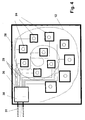
- the intracochlear, electromechanical shown in Fig. 1, generally designated 10 Transducer array is similar to a multi-channel, intracochlear cochlear implant electrode assembly built up. It has a mechanical support 11, which is preferred essentially of a flexible molded part of preferably circular Cross section exists. The molded part is opened by an artificial opening of the cochlea 12 or slid the round window into the inner ear. Instead of a distribution of electrical Stimulation electrodes of a cochlear implant electrode arrangement along this carrier 11 In the present case, a plurality of electromechanical transducers 14 on the output side are arranged in Fig. 1 schematically as cylindrical elements with a circular cross section are shown. Electrical leads to the are located within the carrier 11 Transducers 14; these feed lines are not shown.
- the transducers 14 preferably operate on the principle of dynamic volume change due to a dynamic surface enlargement or reduction in accordance with a driving electrical transducer alternating voltage signal.
- a dynamic volume or surface change is shown schematically in FIG. 2.
- a dashed lines 15 and 16 indicate a minimum and a maximum volume, respectively.
- the volume changes required for an adequate, equivalent sound pressure level of approximately 100 dB SPL result in approximately 2 ⁇ 10 -4 microliters (US Pat. No. 5,772,575).
- the transducers 14 are, for example, distributed equidistantly along the carrier 11 or in logarithmic distances according to the tonotopic location-frequency assignment along the basilar membrane of the inner ear.
- the total diameter of the transducer array arrangement 10 is preferably in the range of 0.4 mm (apical region 18 according to FIG. 1) to 2.0 mm (basal region 19 according to FIG. 1).
- the total length of the transducer array 10 is expediently between 5 mm and 50 mm.
- the transducer elements 14 are for reasons of biocompatibility preferably embedded in the carrier 11 so that they are completely of a thin layer of the carrier material are surrounded (not shown in Fig. 1).
- the carrier 11 of the transducer array 10 consists of a biocompatible and biostable in the inner ear Material, preferably polymers such as corresponding silicones. Between each Transducers 14 can have mechanical damping elements 20 embedded in the carrier 11 be the mechanical wave propagation within the carrier to the neighboring ones Minimize converter elements. In order to obtain high damping values, it is preferred the material of these damping elements 20 with a similar cross-sectional geometry as that of the carrier 11 chosen so that a large mechanical impedance difference to that Carrier material consists.
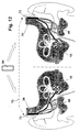
- FIG. 3 schematically shows an electromechanical transducer array to be applied extracochlearly 22.
- Transducer 24 there are several miniaturized electromechanical outputs Transducer 24 thus artificially introduced into the bony wall delimiting the cochlea 12 Openings or bores (cochleostomies) 25 placed that coupling elements 26 attached on the converter output side through the cochlear openings 25 protrude into the lymphatic inner ear spaces.
- Mechanical stimuli of the transducers 24 are generated intracochlearly as volume shifts that lead to an auditory impression.
- the bony cochlear boundary area to be provided with the bores 25 is Operatively accessible from the mastoid in the area of the promontory.
- the transducers 14 and 24 can be based on any known electromechanical transducer principle work, namely electromagnetic, electrodynamic, piezoelectric, magnetostrictive or dielectric (capacitive).
- extracochlear ones are preferred Array embodiment the piezoelectric principle and the dielectric respectively capacitive conversion principle.
- the extracochlear transducer array is preferred 22, but possibly also at least partially the intracochlear transducer array 10, developed or manufactured using microsystem technology methods, a high level of miniaturization and excellent reproducibility of the individual Allow transducers 24 on an array.
- These properties of microsystem technology Generation can be particularly beneficial because it is expected to work as intended Function of the array very much on a phase synchronization of the individual converters arrives.
- a possible microsystem structure of a single converter is shown in of the patent literature by Ron Maynard (WO-A-99/03146).
- the individual electromechanical transducers 14 and 24 are operated by one controlled electronic preprocessing system explained in more detail below that through the respective choice of the spectral transmission range per transducer, the vibratory Amplitude and the phase relationship of the transducers to each other in the overall actuator result the inner ear stimulation a traveling wave formation on the basilar membrane arises, which is possible with the respective external sound event of the traveling waveform comes close, which is intact with undamaged cochlear amplifier and thus intact outer hair cells would result.
- Fig. 4 shows schematically a possible structure of the extracochlear electromechanical 3, which is preferably with microsystem technology Methods can be made.
- Transducer units 24 for example according to WO-A-99/3146
- This substrate 28 includes at the same time the electrical converter feed lines 29 (indicated in FIG. 4).
- an electrical connection field 30 is provided, which is also produced using microsystems technology and the adequate connection of a multi-pole, biocompatible implant line 31 an electronics module 34 illustrated in Figures 6 to 10 enables the contains driving signal processing electronics of the implantable hearing system.
- the substrate 28 can be an electronics module that is also produced using microsystems technology 36 contain, for example, the driver stages driving the converter 24 contain can.
- This module 36 can advantageously also include decoding logic and converter modules included, which enable the connection of a pole-reduced implant line. So can for example the array connection consist of only three lines (ground, data and one Clock signal), with the necessary supply of electrical operating energy through Phantom power can be supplied on the clock signal line.
- the converter driving signals are then available in digitally coded form, which are transmitted serially at a high clock rate.
- An interface module can also be included, which handles the digital data transmission via the implant line advantageously by means of an optical fiber. At Serial data transmission in the electronics module 36 corresponds to the converters Contain 24 assigned D / A converters and driver modules.
- the entire transducer array 22 including carrier structure (substrate) 28 is with a biocompatible casing equipped, for example, from known polymers from implant technology exists (polytetrafluoroethylene, polyurethane, silicones).
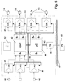
- Fig. 5 shows the possible structure of the signal processing electronics module 34 of the at least partially implantable hearing system.
- the external sound signal Via one or more sound sensors (Microphones) 40, the external sound signal is recorded and converted into electrical signals converted.
- the analog electrical sensor signals are passed to modules 41 where pre-processed, especially pre-amplified, and converted into digital signals (A / D) become.
- This preprocessing can be, for example, in an analog linear or non-linear Pre-amplification and filtering (e.g. anti-aliasing filtering) exist.
- the digitized sensor signals are further processed in a digital signal processor 42 (DSP).
- DSP digital signal processor 42
- the signal processor 42 contains a non-rewritable permanent memory area S 0 , in which the instructions and parameters required for "minimal operation" of the system are stored, as well as memory areas S 1 and S 2 , in which the operating software for the intended function or functions of the implant system are stored.
- the program memories S 1 and S 2 which can be written repeatedly, for accommodating the operating software can be based on EEPROM or static RAM cells, in the latter case it should be ensured that this RAM area is always "buffered" by the implant-internal energy supply system.
- the digital output signals of the signal processor 42 are in digital-to-analog converters (D / A) 43 converted into analog signals and amplified and then the output side supplied electromechanical transducers 14.
- the D / A converter 43 can optionally omitted if, for example, in a hearing system with electromagnetic Output converter, for example a pulse width modulated, serial digital output signal of the signal processor 42 is transmitted directly to the output converter 14.
- the signal processor 42 carries out the intended function of the hearing implant. This includes audio signal processing for the rehabilitation of a hearing impairment and possibly also signal generation in the case of a system with additional Tinnitus masker or noiser function.
- the digital signal processor also contains 42 software modules that control the electromechanical output Transducers 14 cause the spectral, temporal, amplitude and phase-related Transducer signal properties are dimensioned so that on the basilar membrane of the damaged inner ear a traveling wave is generated, that of healthy hearing comes as close as possible. These software modules can be designed statically and dynamically his. Static design should be understood to mean that the software modules based on scientific knowledge, once in the program memory of the signal processor 42 are stored and remain unchanged.
- Dynamic means that this Software modules are “learnable” in time to the desired traveling wave configuration to get as close as possible iteratively.
- the software modules can be designed adaptively and the parameter adjustment by "training” by the Implant carriers and, if necessary, other aids, such as rehabilitation programs, is made.
- a software module can be included, which a optimal simulation of the "healthy" cochlear amplifier based on a adaptable neural network. The training of this neural network can again through the implant carrier and / or with the help of other external Aids are made.
- a method for optimally simulating the "healthy" cochlear amplifier can be the implementation of the principle of "Time-Reversed Acoustics” (TRA) (Fink, M .: “Time-Reversed Acoustics", Scientific American 281: 5 (1999), p. 67-73).
- the output-side converter elements 14 are controlled by means of TRA so that locally limited areas of the cochlea are mechanically stimulated. While in conventional Applications of TRA the registration of the distributed sound event and the The two reversed signals are sent out in the same preparation Steps separated in the present case.
- the distributed events can, for example, in an adequate animal model can be determined intracochlearly; then the time-reversed stimuli in the present application of a hearing system for humans, if necessary under parameter adjustment to the changed geometry of the human cochlea.
- the system according to FIG. 5 contains a further microprocessor module, for example a microcontroller ( ⁇ C) 44 with associated memories S 3 , S 4 and S 5 .
- the memory S 3 is a repeatedly writable memory in which a work program for the microcontroller 44 is stored.
- the operating software components of the implant management system can be stored in the memory areas S 4 and S 5 (for example administrative monitoring and telemetry functions).
- patient-specific, for example audiological adaptation parameters, which can be changed externally can also be stored.
- the microcontroller 44 communicates on the one hand via a bidirectional data bus 45 and a telemetry system (TS) 46 wirelessly (for example by means of inductive coupling) through the closed skin indicated at 47 with an external programming system (PS) 48.
- the programming system 48 can also be a PC-based system appropriate programming, editing, presentation and management software.
- the operating software of the implant system that is to be changed or completely exchanged is transmitted via this telemetry interface and initially stored temporarily in the memory area S 4 and / or S 5 of the microcontroller 44.
- a simple verification of the software transmission can be carried out by a reading process via the telemetry interface before the operating software or the corresponding signal processing parts of this software are transmitted to the program memory areas S 1 , and S 2 of the digital signal processor 42 via a data bus 50.
- the work program for the microcontroller 44 can also be carried out via the telemetry interface completely or partially changed or exchanged with the help of the external unit 48 become.
- the microcontroller 44 controls intra-implant via the bidirectional Data bus 50, the A / D converter 41 of the sensor preprocessing, the D / A converter 43 for Control of the output-side electromechanical converter 14 and the signal processor 42 itself.
- Program parts or entire software modules are also via the data bus 50 transmitted between the outside world, microcontroller 44 and signal processor 42.
- the implant system also contains a primary one or secondary battery cell 52 which provides the individual modules with electrical operating energy provided.
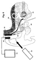
- FIG. 6 schematically shows the structure of a fully implantable hearing system an intracochlear transducer array 10 according to FIG. 1 and an implantable microphone 40.
- a wireless remote control 54 is used to control the implant functions through the implant carrier.
- a charging system with a charger 55 for wireless transcutaneous recharge of a secondary battery in the implant Power supply to the hearing system, for example the battery 52 in FIG. 5, is provided.
- the microphone 40 can advantageously be constructed in the manner known from US Pat. No. 5,814,095 and with a microphone capsule, which is hermetically sealed on all sides in a housing is, as well as with an electrical bushing arrangement for bushing at least an electrical connection from the interior of the housing to the latter Be provided on the outside, wherein the housing has at least two legs, which in are aligned at an angle with respect to each other, the one leg Microphone capsule receives and is provided with a sound inlet membrane, the other leg contains the electrical feedthrough arrangement and opposite the Level of the sound entry membrane is set back, and the geometry of the microphone housing is chosen so that when the microphone is implanted in the mastoid cavity the legs containing the sound entry membrane from the mastoid into an artificial bore protrudes into the back, bony ear canal wall and the sound entry membrane touches the skin of the ear canal wall.
- a fixation element of the type known from US Pat. No. 5,999,632 is expediently provided be that has a sleeve with a cylindrical housing part the Encloses thighs containing the entrance membrane and against those of the ear canal skin projecting, projecting, elastic side facing the auditory canal wall Flange parts is provided.
- the fixation element preferably includes one Bracket, which the flange parts mentioned before implantation against an elastic Restoring force of the flange parts in a pushing through the bore of the Ear canal wall allowing bent position.
- the charging system also includes one connected to the output of the charger 55 Charging coil 56, which is preferably part of a type known from US-A-5 279 292 Transmitter series resonant circuit forms with an unillustrated receive series resonant circuit can be coupled inductively.
- the receiving series resonance circuit can be part of the electronic module 34 in the embodiment according to FIG. 6 and accordingly US-A-5 279 292 form a constant current source for the battery 52 (Fig. 5).
- the receiving series resonant circuit is in a battery charging circuit, which is in Dependence on the respective phase of the charging current flowing in the charging circuit closed over one or the other branch of a full-wave rectifier bridge becomes.
- the electronics module 34 is connected via a microphone line 58 to the microphone 40 and via a transducer array lead 59 to the intracochlear Converter array 10 connected.
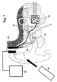
- FIG. 7 schematically shows the structure of a fully implantable hearing system an extracochlear transducer array 22 according to FIGS. 3 and 4 and the implantable one Microphone 40.
- the wireless remote control 54 is also for control in this case the implant functions provided by the implant carrier, and a loading system with charger 55 and charging coil 56 according to FIG. 6 is used for wireless, transcutaneous Reloading a secondary battery 52 in the implant for energy supply of the hearing system.
- the converter array 22 is connected to the electronics module 34 via the Implant line 31 in connection.
- FIG. 8 schematically shows the structure of a partially implantable hearing system with one intracochlear transducer array 10 according to FIG. 1.
- a microphone 40 an electronics module 62 for electronic signal processing largely as shown in FIG. 5 (but without the telemetry system 46), the energy supply 52 and a modulator / transmitter unit 63 in an external body, preferably external module 64 to be worn on the head above the implant.
- the implant is energetically passive.
- His electronics module 34 '(without battery 52) receives its operating energy and converter control data via the Modulator / transmitter unit 63 in the external part 64. It is understood that in such a partially implantable hearing system the transducer array also extracochlear according to the figures 3 and 4 can be executed.
- transcutaneous charging devices 55, 56 are also here for the case of implant-side secondary energy storage elements (batteries 52) and a wireless remote control 54 that controls both electronic modules 34 synchronously Application provided by the implant carrier.
- FIG. 10 shows the binaural application of a hearing implant (here with intracochlear ones Converter arrays 22), in which the signal processing modules 34 via a wireless Connection (for example a bidirectional radio-frequency link indicated at 67) communicate with each other that optimal binaural signal processing and transducer array control is achieved in both implanted inner ears.
- a wireless Connection for example a bidirectional radio-frequency link indicated at 67
- transcutaneous loading devices 55, 56 for the case on the implant side secondary energy storage elements (batteries 52) and one wireless remote control 54 for use by the implant carrier, which are both electronic modules 34 controls synchronously.
- the binaural design of the hearing implant according to FIG. 11 differs from 10 only in that for wireless communication between the Signal processing modules 34 of both system units a structure-borne noise Ultrasonic path 68 with ultrasonic couplers 69 is provided.
- the ultrasonic couplers 69 can as shown in Fig. 11, locally separated from the electronic module 34 and via electrical Lines connected ultrasound receivers and transmitters, which are preferred are firmly coupled to the skull in the mastoid area.
- the ultrasonic coupler can also be integrated in the electronic modules 34 (not shown) if the Electronic modules are implanted in the mastoid area so that an ultrasound body transmission through the skull bone.
- FIG. 10 A further modified embodiment of a binaural hearing implant is shown in FIG.
- digital, bidirectional information on the implant side on a carrier preferably amplitude or frequency modulated and applied to implanted electrodes 72 which are part of a body tissue of the Implant carrier leading data transmission path 73 are. It becomes a modulated one Get tissue flow, in a manner known per se (DE-A-38 31 809) for the desired communication between the signal processing modules 34 both System units.
- a partially implantable system can also be applied binaurally and that then preferably for communication between the two system units corresponding to the exemplary embodiments illustrated in FIGS. 9 to 12 can be provided by binaural applications of fully implantable systems.
- 13 shows a further exemplary embodiment of an intracochlear one which is suitable in the present case electromechanical transducer.
- 13 corresponds to the converter design that of FIG. 2 with the exception that the embedded in the carrier 11
- Converter 14 ' is designed as a hollow cylinder.
- the application of a converter AC voltage signal causes a dynamic volume change indicated by broken lines of the converter. This takes advantage of the fact that a volume reduction of the hollow cylindrical converter 14 'reduces the internal volume of the converter and, as a result, intracochlear fluid 76 from the cylinder cavity 77 is pressed out, as indicated by the arrows 79.
- outlet openings 82 are provided adjacent to the axial converter ends which intracochlear fluid (arrows 79) splashes out when the transducer 14 'due of an applied voltage signal experiences a volume reduction and accordingly the above-described pumping action is exerted on the intracochlear fluid becomes.
Landscapes
- Health & Medical Sciences (AREA)
- Otolaryngology (AREA)
- Engineering & Computer Science (AREA)
- Biomedical Technology (AREA)
- Nuclear Medicine, Radiotherapy & Molecular Imaging (AREA)
- Radiology & Medical Imaging (AREA)
- Life Sciences & Earth Sciences (AREA)
- Animal Behavior & Ethology (AREA)
- General Health & Medical Sciences (AREA)
- Public Health (AREA)
- Veterinary Medicine (AREA)
- Prostheses (AREA)
Applications Claiming Priority (2)
| Application Number | Priority Date | Filing Date | Title |
|---|---|---|---|
| DE10018361A DE10018361C2 (de) | 2000-04-13 | 2000-04-13 | Mindestens teilimplantierbares Cochlea-Implantat-System zur Rehabilitation einer Hörstörung |
| DE10018361 | 2000-04-13 |
Publications (1)
| Publication Number | Publication Date |
|---|---|
| EP1146774A2 true EP1146774A2 (fr) | 2001-10-17 |
Family
ID=7638627
Family Applications (1)
| Application Number | Title | Priority Date | Filing Date |
|---|---|---|---|
| EP00119195A Withdrawn EP1146774A2 (fr) | 2000-04-13 | 2000-09-05 | Système partiellement implantable pour la réhabilitation d'une perturbation de l'ouie |
Country Status (3)
| Country | Link |
|---|---|
| US (1) | US6575894B2 (fr) |
| EP (1) | EP1146774A2 (fr) |
| DE (1) | DE10018361C2 (fr) |
Cited By (1)
| Publication number | Priority date | Publication date | Assignee | Title |
|---|---|---|---|---|
| EP1310137A4 (fr) * | 2000-06-19 | 2005-06-22 | Cochlear Ltd | Processeur sonore pour implant cochleaire |
Families Citing this family (147)
| Publication number | Priority date | Publication date | Assignee | Title |
|---|---|---|---|---|
| US6978159B2 (en) * | 1996-06-19 | 2005-12-20 | Board Of Trustees Of The University Of Illinois | Binaural signal processing using multiple acoustic sensors and digital filtering |
| US7787647B2 (en) | 1997-01-13 | 2010-08-31 | Micro Ear Technology, Inc. | Portable system for programming hearing aids |
| US20030036746A1 (en) | 2001-08-16 | 2003-02-20 | Avi Penner | Devices for intrabody delivery of molecules and systems and methods utilizing same |
| US8260430B2 (en) | 2010-07-01 | 2012-09-04 | Cochlear Limited | Stimulation channel selection for a stimulating medical device |
| US6904402B1 (en) * | 1999-11-05 | 2005-06-07 | Microsoft Corporation | System and iterative method for lexicon, segmentation and language model joint optimization |
| DK1252799T3 (da) * | 2000-01-20 | 2012-01-23 | Starkey Lab Inc | Fremgangsmåde og apparat til tilpasning af høreapparater |
| DE10018334C1 (de) * | 2000-04-13 | 2002-02-28 | Implex Hear Tech Ag | Mindestens teilimplantierbares System zur Rehabilitation einer Hörstörung |
| DK1312239T3 (da) * | 2000-05-10 | 2007-04-30 | Univ Illinois | Teknikker til undertrykkelse af interferens |
| AUPQ952800A0 (en) * | 2000-08-21 | 2000-09-14 | Cochlear Limited | Power efficient electrical stimulation |
| US8285382B2 (en) * | 2000-08-21 | 2012-10-09 | Cochlear Limited | Determining stimulation signals for neural stimulation |
| US7822478B2 (en) * | 2000-08-21 | 2010-10-26 | Cochlear Limited | Compressed neural coding |
| US9008786B2 (en) * | 2000-08-21 | 2015-04-14 | Cochlear Limited | Determining stimulation signals for neural stimulation |
| US6661180B2 (en) * | 2001-03-22 | 2003-12-09 | Semiconductor Energy Laboratory Co., Ltd. | Light emitting device, driving method for the same and electronic apparatus |
| US7962226B2 (en) * | 2001-04-06 | 2011-06-14 | Cochlear Limited | Cochlear endosteal electrode carrier member |
| WO2002080817A1 (fr) * | 2001-04-06 | 2002-10-17 | Cochlear Limited | Electrode endo-osseuse |
| WO2002082982A1 (fr) * | 2001-04-18 | 2002-10-24 | Cochlear Limited | Procede et appareil de mesure de reponses neuronales evoquees |
| AUPR604801A0 (en) * | 2001-06-29 | 2001-07-26 | Cochlear Limited | Multi-electrode cochlear implant system with distributed electronics |
| US10576275B2 (en) | 2001-07-06 | 2020-03-03 | Cochlear Limited | System and method for configuring an external device using operating parameters from an implanted device |
| US20100030130A1 (en) * | 2001-11-09 | 2010-02-04 | Cochlear Limited | Pharmaceutical intervention for modulation of neural plasticity |
| KR100492515B1 (ko) * | 2002-04-29 | 2005-06-03 | 주식회사 뉴로바이오시스 | 인공 와우용 전극 구조물 및 그 제조방법 |
| AUPS318202A0 (en) * | 2002-06-26 | 2002-07-18 | Cochlear Limited | Parametric fitting of a cochlear implant |
| AUPS322702A0 (en) | 2002-06-28 | 2002-07-18 | Cochlear Limited | Cochlear implant electrode array |
| AU2002950754A0 (en) | 2002-08-09 | 2002-09-12 | Cochlear Limited | Mechanical design for a cochlear implant |
| US7974700B1 (en) * | 2002-08-09 | 2011-07-05 | Cochlear Limited | Cochlear implant component having a unitary faceplate |
| AU2002950755A0 (en) | 2002-08-09 | 2002-09-12 | Cochlear Limited | Fixation system for a cochlear implant |
| US7702395B2 (en) * | 2002-08-19 | 2010-04-20 | Arizona Board Of Regents, A Body Corporate, Acting For And On Behalf Of Arizona State University | Neurostimulator |
| AU2002951218A0 (en) * | 2002-09-04 | 2002-09-19 | Cochlear Limited | Method and apparatus for measurement of evoked neural response |
| EP1536852B1 (fr) * | 2002-09-10 | 2016-11-16 | MED-EL Elektromedizinische Geräte GmbH | Dispositif medical implantable a plusieurs transducteurs |
| DE60332871D1 (de) * | 2002-12-09 | 2010-07-15 | Medtronic Inc | Verbindungsmodul für eine modulare implantierbare medizinische vorrichtung |
| US7596408B2 (en) * | 2002-12-09 | 2009-09-29 | Medtronic, Inc. | Implantable medical device with anti-infection agent |
| US7512448B2 (en) | 2003-01-10 | 2009-03-31 | Phonak Ag | Electrode placement for wireless intrabody communication between components of a hearing system |
| US7945064B2 (en) * | 2003-04-09 | 2011-05-17 | Board Of Trustees Of The University Of Illinois | Intrabody communication with ultrasound |
| US7076072B2 (en) * | 2003-04-09 | 2006-07-11 | Board Of Trustees For The University Of Illinois | Systems and methods for interference-suppression with directional sensing patterns |
| AU2003901852A0 (en) * | 2003-04-16 | 2003-05-01 | Cochlear Limited | Cochlear electrode array |
| AU2003901867A0 (en) | 2003-04-17 | 2003-05-08 | Cochlear Limited | Osseointegration fixation system for an implant |
| US20050004637A1 (en) * | 2003-05-16 | 2005-01-06 | Ruchika Singhal | Explantation of implantable medical device |
| US7263401B2 (en) * | 2003-05-16 | 2007-08-28 | Medtronic, Inc. | Implantable medical device with a nonhermetic battery |
| US20050003268A1 (en) * | 2003-05-16 | 2005-01-06 | Scott Erik R. | Battery housing configuration |
| US7317947B2 (en) * | 2003-05-16 | 2008-01-08 | Medtronic, Inc. | Headset recharger for cranially implantable medical devices |
| AU2003903579A0 (en) * | 2003-07-11 | 2003-07-24 | Cochlear Limited | Three wire headset |
| AU2003903576A0 (en) * | 2003-07-11 | 2003-07-24 | Cochlear Limited | Audio path diagnostics |
| AU2003904085A0 (en) * | 2003-08-04 | 2003-08-21 | Cochlear Limited | Magnetic on/off switch for speech processor |
| AU2003904139A0 (en) * | 2003-08-07 | 2003-08-21 | Cochlear Limited | Miniature switches |
| US7184837B2 (en) * | 2003-09-15 | 2007-02-27 | Medtronic, Inc. | Selection of neurostimulator parameter configurations using bayesian networks |
| US7252090B2 (en) * | 2003-09-15 | 2007-08-07 | Medtronic, Inc. | Selection of neurostimulator parameter configurations using neural network |
| US7239926B2 (en) * | 2003-09-15 | 2007-07-03 | Medtronic, Inc. | Selection of neurostimulator parameter configurations using genetic algorithms |
| US7617002B2 (en) * | 2003-09-15 | 2009-11-10 | Medtronic, Inc. | Selection of neurostimulator parameter configurations using decision trees |
| US7596399B2 (en) * | 2004-04-29 | 2009-09-29 | Medtronic, Inc | Implantation of implantable medical device |
| US20050245984A1 (en) * | 2004-04-30 | 2005-11-03 | Medtronic, Inc. | Implantable medical device with lubricious material |
| US20060184212A1 (en) * | 2004-05-07 | 2006-08-17 | Faltys Michael A | Cochlear Stimulation Device |
| US7801617B2 (en) | 2005-10-31 | 2010-09-21 | Cochlear Limited | Automatic measurement of neural response concurrent with psychophysics measurement of stimulating device recipient |
| CA2569724A1 (fr) * | 2004-06-15 | 2005-12-29 | Cochlear Americas | Determination automatique du seuil d'une reponse neuronale evoquee |
| US8190268B2 (en) * | 2004-06-15 | 2012-05-29 | Cochlear Limited | Automatic measurement of an evoked neural response concurrent with an indication of a psychophysics reaction |
| AU2005202837B2 (en) * | 2004-06-28 | 2011-05-26 | Hearworks Pty Limited | Selective resolution speech processing |
| US7489967B2 (en) * | 2004-07-09 | 2009-02-10 | Cardiac Pacemakers, Inc. | Method and apparatus of acoustic communication for implantable medical device |
| US7668325B2 (en) | 2005-05-03 | 2010-02-23 | Earlens Corporation | Hearing system having an open chamber for housing components and reducing the occlusion effect |
| US7867160B2 (en) | 2004-10-12 | 2011-01-11 | Earlens Corporation | Systems and methods for photo-mechanical hearing transduction |
| US20060025833A1 (en) * | 2004-07-29 | 2006-02-02 | Cochlear Limited | Variable width electrode scheme |
| US7421298B2 (en) * | 2004-09-07 | 2008-09-02 | Cochlear Limited | Multiple channel-electrode mapping |
| US20060085051A1 (en) * | 2004-10-19 | 2006-04-20 | Fritsch Michael H | Electrical implants |
| ATE484232T1 (de) * | 2004-11-24 | 2010-10-15 | Remon Medical Technologies Ltd | Implantierbares medizinprodukt mit integriertem akustischem wandler |
| US7522962B1 (en) | 2004-12-03 | 2009-04-21 | Remon Medical Technologies, Ltd | Implantable medical device with integrated acoustic transducer |
| US8170677B2 (en) * | 2005-04-13 | 2012-05-01 | Cochlear Limited | Recording and retrieval of sound data in a hearing prosthesis |
| CA2606787A1 (fr) | 2005-04-29 | 2006-11-09 | Cochlear Americas | Stimulation focalisee dans un dispositif de stimulation medical |
| CN100502819C (zh) * | 2005-05-24 | 2009-06-24 | 北京大学科技开发部 | 制造适合汉语语音编码策略的人工耳蜗的方法 |
| US8805547B2 (en) * | 2005-06-30 | 2014-08-12 | Domestic Legacy Limited Partnership | Extra-cochlear implanted hearing aid device |
| US7615012B2 (en) * | 2005-08-26 | 2009-11-10 | Cardiac Pacemakers, Inc. | Broadband acoustic sensor for an implantable medical device |
| US7570998B2 (en) * | 2005-08-26 | 2009-08-04 | Cardiac Pacemakers, Inc. | Acoustic communication transducer in implantable medical device header |
| US8328862B2 (en) * | 2005-10-06 | 2012-12-11 | The Johns Hopkins University | MRI compatible vascular occlusive devices and related methods of treatment and methods of monitoring implanted devices |
| WO2007053882A1 (fr) * | 2005-11-10 | 2007-05-18 | Cochlear Limited | Arrangement pour la fixation d'un appareil médical implantable |
| US7937154B2 (en) * | 2005-12-08 | 2011-05-03 | Cochlear Limited | Promoting curvature and maintaining orientation of an electrode carrier member of a stimulating medical device |
| US20070162098A1 (en) * | 2005-12-08 | 2007-07-12 | Cochlear Limited | Prosthetic hearing implant electrode assembly having optimal length for atraumatic implantation |
| US20080154339A1 (en) * | 2006-12-21 | 2008-06-26 | Cochlear Limited | Electrically Nonconductive Occludent For Tissue Openings |
| US8784312B2 (en) * | 2006-02-10 | 2014-07-22 | Cochlear Limited | Recognition of implantable medical device |
| US7650194B2 (en) * | 2006-03-22 | 2010-01-19 | Fritsch Michael H | Intracochlear nanotechnology and perfusion hearing aid device |
| US8571675B2 (en) * | 2006-04-21 | 2013-10-29 | Cochlear Limited | Determining operating parameters for a stimulating medical device |
| US9084901B2 (en) | 2006-04-28 | 2015-07-21 | Medtronic, Inc. | Cranial implant |
| US8306624B2 (en) | 2006-04-28 | 2012-11-06 | Medtronic, Inc. | Patient-individualized efficacy rating |
| US8380300B2 (en) * | 2006-04-28 | 2013-02-19 | Medtronic, Inc. | Efficacy visualization |
| US7715920B2 (en) | 2006-04-28 | 2010-05-11 | Medtronic, Inc. | Tree-based electrical stimulator programming |
| EP2043740A2 (fr) * | 2006-07-21 | 2009-04-08 | Cardiac Pacemakers, Inc. | Transducteur à ultrasons pour un dispositif médical implanté à cavité métallique |
| US7912548B2 (en) * | 2006-07-21 | 2011-03-22 | Cardiac Pacemakers, Inc. | Resonant structures for implantable devices |
| CA2601662A1 (fr) | 2006-09-18 | 2008-03-18 | Matthias Mullenborn | Interface sans fil pour programmer des dispositifs d'aide auditive |
| US8718795B2 (en) * | 2007-03-20 | 2014-05-06 | Cochlear Limited | Securing an implanted medical device in a patient |
| EP1972359B1 (fr) | 2007-03-20 | 2015-01-28 | Cochlear Limited | Sécurisation du dispositif médical implanté sur un patient |
| CA2681880A1 (fr) * | 2007-03-29 | 2008-10-09 | Vibrant Med-El Hearing Technology Gmbh | Systemes de stimulation auditive implantables ayant un transducteur et un milieu de transduction |
| US8825161B1 (en) | 2007-05-17 | 2014-09-02 | Cardiac Pacemakers, Inc. | Acoustic transducer for an implantable medical device |
| US7634318B2 (en) * | 2007-06-14 | 2009-12-15 | Cardiac Pacemakers, Inc. | Multi-element acoustic recharging system |
| WO2009037689A2 (fr) * | 2007-09-20 | 2009-03-26 | Estimme Ltd | Stimulation électrique dans l'oreille moyenne pour le traitement de troubles auditifs |
| WO2009049320A1 (fr) | 2007-10-12 | 2009-04-16 | Earlens Corporation | Système et procédé multifonction pour une audition et une communication intégrées avec gestion de l'annulation du bruit et de la contre-réaction |
| JP5567491B2 (ja) * | 2007-12-18 | 2014-08-06 | コクレア リミテッド | 蝸牛インプラントの調整 |
| US8612011B2 (en) * | 2008-01-22 | 2013-12-17 | Cochlear Limited | Recipient-controlled fitting of a hearing prosthesis |
| WO2009155358A1 (fr) | 2008-06-17 | 2009-12-23 | Earlens Corporation | Dispositifs d’audition électromécaniques optiques dotés de composants d’alimentation et de signal séparés |
| US8396239B2 (en) | 2008-06-17 | 2013-03-12 | Earlens Corporation | Optical electro-mechanical hearing devices with combined power and signal architectures |
| WO2009155361A1 (fr) | 2008-06-17 | 2009-12-23 | Earlens Corporation | Dispositifs auditifs électro-mécaniques optiques présentant une architecture combinant puissance et signal |
| DK3509324T3 (da) | 2008-09-22 | 2023-10-02 | Earlens Corp | Balancerede armaturindretninger og fremgangsmåder til at høre |
| US9393432B2 (en) | 2008-10-31 | 2016-07-19 | Medtronic, Inc. | Non-hermetic direct current interconnect |
| WO2010081201A1 (fr) | 2009-01-19 | 2010-07-22 | Cochlear Limited | Modification de surface pour dispositif médical implantable |
| US8954158B2 (en) * | 2009-02-05 | 2015-02-10 | Cochlear Limited | Multi-electrode channel configurations |
| DK2438768T3 (en) * | 2009-06-05 | 2016-06-06 | Earlens Corp | Optically coupled acoustically mellemøreimplantatindretning |
| US9544700B2 (en) * | 2009-06-15 | 2017-01-10 | Earlens Corporation | Optically coupled active ossicular replacement prosthesis |
| US8401214B2 (en) * | 2009-06-18 | 2013-03-19 | Earlens Corporation | Eardrum implantable devices for hearing systems and methods |
| CN102640435B (zh) * | 2009-06-18 | 2016-11-16 | 伊尔莱茵斯公司 | 光学耦合的耳蜗植入系统及方法 |
| CN102598714A (zh) | 2009-06-22 | 2012-07-18 | 音束有限责任公司 | 圆窗耦合的听力系统和方法 |
| WO2011005479A2 (fr) | 2009-06-22 | 2011-01-13 | SoundBeam LLC | Systèmes et procédés de conduction osseuse à couplage optique |
| WO2010151636A2 (fr) | 2009-06-24 | 2010-12-29 | SoundBeam LLC | Dispositifs et procédés de stimulation cochléaire optique |
| US8715154B2 (en) | 2009-06-24 | 2014-05-06 | Earlens Corporation | Optically coupled cochlear actuator systems and methods |
| AU2009222439B2 (en) * | 2009-09-28 | 2011-07-21 | Cochlear Limited | Method and circuitry for measurement and control of stimulation current |
| US8909348B2 (en) | 2010-03-30 | 2014-12-09 | Domestic Legacy Limited Partnership | Cochlear implant stabilization and positioning device |
| US8625828B2 (en) | 2010-04-30 | 2014-01-07 | Cochlear Limited | Hearing prosthesis having an on-board fitting system |
| US8594806B2 (en) | 2010-04-30 | 2013-11-26 | Cyberonics, Inc. | Recharging and communication lead for an implantable device |
| US9031661B2 (en) | 2010-05-18 | 2015-05-12 | Cochlear Limited | Multi-electrode channel configurations for a hearing prosthesis |
| US9155886B2 (en) | 2010-10-28 | 2015-10-13 | Cochlear Limited | Fitting an auditory prosthesis |
| WO2012088187A2 (fr) | 2010-12-20 | 2012-06-28 | SoundBeam LLC | Appareil auditif intra-auriculaire anatomiquement personnalisé |
| US9352153B2 (en) | 2011-01-24 | 2016-05-31 | Cochlear Limited | Systems and methods for detecting nerve stimulation with an implanted prosthesis |
| US9272142B2 (en) | 2011-01-28 | 2016-03-01 | Cochlear Limited | Systems and methods for using a simplified user interface for hearing prosthesis fitting |
| US8515540B2 (en) | 2011-02-24 | 2013-08-20 | Cochlear Limited | Feedthrough having a non-linear conductor |
| US10419861B2 (en) | 2011-05-24 | 2019-09-17 | Cochlear Limited | Convertibility of a bone conduction device |
| US20130096366A1 (en) | 2011-10-12 | 2013-04-18 | Wim Bervoets | Implantable medical device |
| US9343923B2 (en) | 2012-08-23 | 2016-05-17 | Cyberonics, Inc. | Implantable medical device with backscatter signal based communication |
| US9049527B2 (en) | 2012-08-28 | 2015-06-02 | Cochlear Limited | Removable attachment of a passive transcutaneous bone conduction device with limited skin deformation |
| US9935498B2 (en) | 2012-09-25 | 2018-04-03 | Cyberonics, Inc. | Communication efficiency with an implantable medical device using a circulator and a backscatter signal |
| US11229789B2 (en) | 2013-05-30 | 2022-01-25 | Neurostim Oab, Inc. | Neuro activator with controller |
| WO2014194200A1 (fr) | 2013-05-30 | 2014-12-04 | Creasey Graham H | Stimulation neurologique topique |
| CN103356308B (zh) * | 2013-07-11 | 2015-05-20 | 山东大学 | 阵列光纤激光诱发听觉装置及光信号转换方法 |
| US10034103B2 (en) | 2014-03-18 | 2018-07-24 | Earlens Corporation | High fidelity and reduced feedback contact hearing apparatus and methods |
| EP3169396B1 (fr) | 2014-07-14 | 2021-04-21 | Earlens Corporation | Limitation de crête et polarisation coulissante pour dispositifs auditifs optiques |
| US9924276B2 (en) | 2014-11-26 | 2018-03-20 | Earlens Corporation | Adjustable venting for hearing instruments |
| US10105539B2 (en) | 2014-12-17 | 2018-10-23 | Cochlear Limited | Configuring a stimulation unit of a hearing device |
| US11077301B2 (en) | 2015-02-21 | 2021-08-03 | NeurostimOAB, Inc. | Topical nerve stimulator and sensor for bladder control |
| DE102015114514B4 (de) | 2015-08-31 | 2017-03-30 | Gottfried Wilhelm Leibniz Universität Hannover | Cochlea-Implantat |
| EP3355801B1 (fr) | 2015-10-02 | 2021-05-19 | Earlens Corporation | Appareil intra-auriculaire personnalisé d'administration de médicament |
| US10492010B2 (en) | 2015-12-30 | 2019-11-26 | Earlens Corporations | Damping in contact hearing systems |
| US11350226B2 (en) | 2015-12-30 | 2022-05-31 | Earlens Corporation | Charging protocol for rechargeable hearing systems |
| US10306381B2 (en) | 2015-12-30 | 2019-05-28 | Earlens Corporation | Charging protocol for rechargable hearing systems |
| US10602284B2 (en) | 2016-07-18 | 2020-03-24 | Cochlear Limited | Transducer management |
| US20180077504A1 (en) | 2016-09-09 | 2018-03-15 | Earlens Corporation | Contact hearing systems, apparatus and methods |
| WO2018093733A1 (fr) | 2016-11-15 | 2018-05-24 | Earlens Corporation | Procédure d'impression améliorée |
| WO2018144732A1 (fr) * | 2017-02-01 | 2018-08-09 | The Trustees Of Indiana University | Implant cochléaire |
| EP3706856A4 (fr) | 2017-11-07 | 2021-08-18 | Neurostim Oab, Inc. | Activateur de nerf non invasif à circuit adaptatif |
| WO2019173470A1 (fr) | 2018-03-07 | 2019-09-12 | Earlens Corporation | Dispositif auditif de contact et matériaux de structure de rétention |
| WO2019199680A1 (fr) | 2018-04-09 | 2019-10-17 | Earlens Corporation | Filtre dynamique |
| US11642524B2 (en) * | 2019-04-25 | 2023-05-09 | The Regents Of The University Of California | Methods and systems for treating tinnitus with transtympanic electrical stimulation |
| US11458311B2 (en) | 2019-06-26 | 2022-10-04 | Neurostim Technologies Llc | Non-invasive nerve activator patch with adaptive circuit |
| EP4021563B1 (fr) | 2019-08-29 | 2024-12-04 | Cochlear Limited | Support implantable avec stabilisateur intégré |
| KR20220115802A (ko) | 2019-12-16 | 2022-08-18 | 뉴로스팀 테크놀로지스 엘엘씨 | 부스트 전하 전달 기능이 있는 비침습적 신경 액티베이터 |
| US12335692B2 (en) | 2020-02-21 | 2025-06-17 | Cochlear Limited | Implantable tinnitus therapy |
Family Cites Families (43)
| Publication number | Priority date | Publication date | Assignee | Title |
|---|---|---|---|---|
| US3557775A (en) | 1963-12-27 | 1971-01-26 | Jack Lawrence Mahoney | Method of implanting a hearing aid |
| US3712962A (en) | 1971-04-05 | 1973-01-23 | J Epley | Implantable piezoelectric hearing aid |
| US3764748A (en) | 1972-05-19 | 1973-10-09 | J Branch | Implanted hearing aids |
| US4352960A (en) | 1980-09-30 | 1982-10-05 | Baptist Medical Center Of Oklahoma, Inc. | Magnetic transcutaneous mount for external device of an associated implant |
| US4441210A (en) | 1981-09-18 | 1984-04-03 | Hochmair Erwin S | Transcutaneous signal transmission system and methods |
| US4729366A (en) | 1984-12-04 | 1988-03-08 | Medical Devices Group, Inc. | Implantable hearing aid and method of improving hearing |
| US4593696A (en) | 1985-01-17 | 1986-06-10 | Hochmair Ingeborg | Auditory stimulation using CW and pulsed signals |
| EP0200321A3 (fr) | 1985-03-20 | 1987-03-11 | Ingeborg J. Hochmair | Système de transmission de signal transdermique |
| US5015225A (en) | 1985-05-22 | 1991-05-14 | Xomed, Inc. | Implantable electromagnetic middle-ear bone-conduction hearing aid device |
| US4988333A (en) | 1988-09-09 | 1991-01-29 | Storz Instrument Company | Implantable middle ear hearing aid system and acoustic coupler therefor |
| DE3831809A1 (de) | 1988-09-19 | 1990-03-22 | Funke Hermann | Zur mindestens teilweisen implantation im lebenden koerper bestimmtes geraet |
| US5015224A (en) | 1988-10-17 | 1991-05-14 | Maniglia Anthony J | Partially implantable hearing aid device |
| DE8815877U1 (de) | 1988-12-22 | 1989-04-27 | Junker, Franz, 76275 Ettlingen | Tinnitus-Maskierungsgerät |
| DE3940632C1 (en) | 1989-06-02 | 1990-12-06 | Hortmann Gmbh, 7449 Neckartenzlingen, De | Hearing aid directly exciting inner ear - has microphone encapsulated for implantation in tympanic cavity or mastoid region |
| US5271397A (en) | 1989-09-08 | 1993-12-21 | Cochlear Pty. Ltd. | Multi-peak speech processor |
| US5095904A (en) | 1989-09-08 | 1992-03-17 | Cochlear Pty. Ltd. | Multi-peak speech procession |
| US5603726A (en) | 1989-09-22 | 1997-02-18 | Alfred E. Mann Foundation For Scientific Research | Multichannel cochlear implant system including wearable speech processor |
| US5061282A (en) * | 1989-10-10 | 1991-10-29 | Jacobs Jared J | Cochlear implant auditory prosthesis |
| DE4104358A1 (de) | 1991-02-13 | 1992-08-20 | Implex Gmbh | Implantierbares hoergeraet zur anregung des innenohres |
| DE4104359A1 (de) | 1991-02-13 | 1992-08-20 | Implex Gmbh | Ladesystem fuer implantierbare hoerhilfen und tinnitus-maskierer |
| US5597380A (en) | 1991-07-02 | 1997-01-28 | Cochlear Ltd. | Spectral maxima sound processor |
| EP0537385A1 (fr) | 1991-10-14 | 1993-04-21 | DORN GmbH | Appareil destiné à la thérapie du bourdonnement d'oreille |
| US5360388A (en) | 1992-10-09 | 1994-11-01 | The University Of Virginia Patents Foundation | Round window electromagnetic implantable hearing aid |
| US5531787A (en) | 1993-01-25 | 1996-07-02 | Lesinski; S. George | Implantable auditory system with micromachined microsensor and microactuator |
| US5624376A (en) | 1993-07-01 | 1997-04-29 | Symphonix Devices, Inc. | Implantable and external hearing systems having a floating mass transducer |
| US5601617A (en) | 1995-04-26 | 1997-02-11 | Advanced Bionics Corporation | Multichannel cochlear prosthesis with flexible control of stimulus waveforms |
| US5626629A (en) | 1995-05-31 | 1997-05-06 | Advanced Bionics Corporation | Programming of a speech processor for an implantable cochlear stimulator |
| US5772575A (en) | 1995-09-22 | 1998-06-30 | S. George Lesinski | Implantable hearing aid |
| US5795287A (en) | 1996-01-03 | 1998-08-18 | Symphonix Devices, Inc. | Tinnitus masker for direct drive hearing devices |
| DE69738884D1 (de) * | 1996-02-15 | 2008-09-18 | Armand P Neukermans | Verbesserte biokompatible wandler |
| US5951601A (en) | 1996-03-25 | 1999-09-14 | Lesinski; S. George | Attaching an implantable hearing aid microactuator |
| JP3801212B2 (ja) * | 1996-05-24 | 2006-07-26 | エス ジョージ レジンスキー | 埋込み可能な補聴器用改良マイクロフォン |
| EP0912146B1 (fr) | 1996-07-19 | 2009-11-18 | Armand P. Neukermans | Microactionneur biocompatible et implantable pour prothese auditive |
| US6005955A (en) | 1996-08-07 | 1999-12-21 | St. Croix Medical, Inc. | Middle ear transducer |
| US5997466A (en) | 1996-08-07 | 1999-12-07 | St. Croix Medical, Inc. | Implantable hearing system having multiple transducers |
| US5814095A (en) | 1996-09-18 | 1998-09-29 | Implex Gmbh Spezialhorgerate | Implantable microphone and implantable hearing aids utilizing same |
| DE29616956U1 (de) | 1996-09-28 | 1996-12-19 | auric Hörsysteme GmbH & Co. KG, 48429 Rheine | Tinnitus-Masker |
| DE19758573C2 (de) | 1997-11-26 | 2001-03-01 | Implex Hear Tech Ag | Fixationselement für ein implantierbares Mikrofon |
| DE19827898C1 (de) | 1998-06-23 | 1999-11-11 | Hans Leysieffer | Verfahren und Vorrichtung zur Versorgung eines teil- oder vollimplantierten aktiven Gerätes mit elektrischer Energie |
| DE19838137A1 (de) | 1998-08-21 | 2000-03-02 | Implex Hear Tech Ag | Vorrichtung und Verfahren zum Laden von wiederaufladbaren Akkumulatoren von Implantaten |
| DE19840211C1 (de) | 1998-09-03 | 1999-12-30 | Implex Hear Tech Ag | Wandler für teil- oder vollimplantierbare Hörgeräte |
| DE19858398C1 (de) | 1998-12-17 | 2000-03-02 | Implex Hear Tech Ag | Implantierbares Gerät zum Behandeln eines Tinnitus |
| DE19915846C1 (de) | 1999-04-08 | 2000-08-31 | Implex Hear Tech Ag | Mindestens teilweise implantierbares System zur Rehabilitation einer Hörstörung |
-
2000
- 2000-04-13 DE DE10018361A patent/DE10018361C2/de not_active Expired - Fee Related
- 2000-09-05 EP EP00119195A patent/EP1146774A2/fr not_active Withdrawn
-
2001
- 2001-04-13 US US09/833,704 patent/US6575894B2/en not_active Expired - Fee Related
Cited By (3)
| Publication number | Priority date | Publication date | Assignee | Title |
|---|---|---|---|---|
| EP1310137A4 (fr) * | 2000-06-19 | 2005-06-22 | Cochlear Ltd | Processeur sonore pour implant cochleaire |
| US7082332B2 (en) | 2000-06-19 | 2006-07-25 | Cochlear Limited | Sound processor for a cochlear implant |
| US9084892B2 (en) | 2000-06-19 | 2015-07-21 | Cochlear Limited | Sound processor for a cochlear implant |
Also Published As
| Publication number | Publication date |
|---|---|
| DE10018361C2 (de) | 2002-10-10 |
| US6575894B2 (en) | 2003-06-10 |
| US20020029070A1 (en) | 2002-03-07 |
| DE10018361A1 (de) | 2001-10-25 |
Similar Documents
| Publication | Publication Date | Title |
|---|---|---|
| EP1191815B1 (fr) | Système auditif au moins partiellement implantable avec stimulation mécanique d'un espace lymphatique de l'oreille interne | |
| DE10018361C2 (de) | Mindestens teilimplantierbares Cochlea-Implantat-System zur Rehabilitation einer Hörstörung | |
| DE10031832C2 (de) | Hörgerät zur Rehabilitation einer Hörstörung | |
| EP1145734B1 (fr) | Système au moins partiellement implantable de réhabilitation d'un trouble auditif | |
| DE10018360C2 (de) | Mindestens teilimplantierbares System zur Rehabilitation einer Hörstörung | |
| EP1246503B1 (fr) | Système auditif entièrement implantable | |
| DE19915846C1 (de) | Mindestens teilweise implantierbares System zur Rehabilitation einer Hörstörung | |
| EP1179969B1 (fr) | Système auditif au moins partiellement implantable | |
| EP1181950B1 (fr) | Système auditif implantable comportant des moyens de mesure de la qualité d'accouplement | |
| EP1181952B1 (fr) | Dispositif médical implantable actif comportant un boîtier fermé hermétiquement | |
| EP0831673B1 (fr) | Microphone implantable | |
| EP1014755A2 (fr) | Prothèse auditive implantable avec masquage de acuphène |
Legal Events
| Date | Code | Title | Description |
|---|---|---|---|
| PUAI | Public reference made under article 153(3) epc to a published international application that has entered the european phase |
Free format text: ORIGINAL CODE: 0009012 |
|
| AK | Designated contracting states |
Kind code of ref document: A2 Designated state(s): AT BE CH CY DE DK ES FI FR GB GR IE IT LI LU MC NL PT SE |
|
| AX | Request for extension of the european patent |
Free format text: AL;LT;LV;MK;RO;SI |
|
| RAP1 | Party data changed (applicant data changed or rights of an application transferred) |
Owner name: COCHLEAR LIMITED |
|
| STAA | Information on the status of an ep patent application or granted ep patent |
Free format text: STATUS: THE APPLICATION HAS BEEN WITHDRAWN |
|
| 18W | Application withdrawn |
Effective date: 20041130 |