EP1146820B1 - Venenstripper - Google Patents
Venenstripper Download PDFInfo
- Publication number
- EP1146820B1 EP1146820B1 EP00903027A EP00903027A EP1146820B1 EP 1146820 B1 EP1146820 B1 EP 1146820B1 EP 00903027 A EP00903027 A EP 00903027A EP 00903027 A EP00903027 A EP 00903027A EP 1146820 B1 EP1146820 B1 EP 1146820B1
- Authority
- EP
- European Patent Office
- Prior art keywords
- catheter
- cutting
- catheter element
- vsm
- cutting elements
- Prior art date
- Legal status (The legal status is an assumption and is not a legal conclusion. Google has not performed a legal analysis and makes no representation as to the accuracy of the status listed.)
- Expired - Lifetime
Links
- 210000003462 vein Anatomy 0.000 title claims abstract description 39
- 238000005520 cutting process Methods 0.000 claims abstract description 140
- 230000007935 neutral effect Effects 0.000 claims abstract description 25
- 238000000034 method Methods 0.000 claims description 12
- 230000008719 thickening Effects 0.000 claims description 11
- 210000003127 knee Anatomy 0.000 description 26
- 210000002414 leg Anatomy 0.000 description 24
- 210000004013 groin Anatomy 0.000 description 18
- 230000006378 damage Effects 0.000 description 8
- 238000007920 subcutaneous administration Methods 0.000 description 6
- 210000003423 ankle Anatomy 0.000 description 5
- 239000008280 blood Substances 0.000 description 5
- 210000004369 blood Anatomy 0.000 description 5
- 230000006870 function Effects 0.000 description 4
- 210000000689 upper leg Anatomy 0.000 description 4
- 206010046996 Varicose vein Diseases 0.000 description 2
- 239000002537 cosmetic Substances 0.000 description 2
- 210000002683 foot Anatomy 0.000 description 2
- 239000002184 metal Substances 0.000 description 2
- 231100000241 scar Toxicity 0.000 description 2
- 208000027185 varicose disease Diseases 0.000 description 2
- VGGSQFUCUMXWEO-UHFFFAOYSA-N Ethene Chemical compound C=C VGGSQFUCUMXWEO-UHFFFAOYSA-N 0.000 description 1
- 239000005977 Ethylene Substances 0.000 description 1
- 208000027418 Wounds and injury Diseases 0.000 description 1
- 230000005856 abnormality Effects 0.000 description 1
- 238000009825 accumulation Methods 0.000 description 1
- 210000000577 adipose tissue Anatomy 0.000 description 1
- 238000013459 approach Methods 0.000 description 1
- 210000001367 artery Anatomy 0.000 description 1
- 230000017531 blood circulation Effects 0.000 description 1
- 230000036772 blood pressure Effects 0.000 description 1
- 230000006835 compression Effects 0.000 description 1
- 238000007906 compression Methods 0.000 description 1
- 238000010276 construction Methods 0.000 description 1
- 230000001595 contractor effect Effects 0.000 description 1
- 238000007599 discharging Methods 0.000 description 1
- 230000000694 effects Effects 0.000 description 1
- 238000013171 endarterectomy Methods 0.000 description 1
- 239000012530 fluid Substances 0.000 description 1
- 230000001771 impaired effect Effects 0.000 description 1
- 208000014674 injury Diseases 0.000 description 1
- 238000009434 installation Methods 0.000 description 1
- 239000000463 material Substances 0.000 description 1
- 210000003205 muscle Anatomy 0.000 description 1
- 210000005036 nerve Anatomy 0.000 description 1
- 238000004806 packaging method and process Methods 0.000 description 1
- 238000005086 pumping Methods 0.000 description 1
- 230000001105 regulatory effect Effects 0.000 description 1
- 238000001356 surgical procedure Methods 0.000 description 1
- 210000001519 tissue Anatomy 0.000 description 1
- 210000002073 venous valve Anatomy 0.000 description 1
Images


Classifications
-
- A—HUMAN NECESSITIES
- A61—MEDICAL OR VETERINARY SCIENCE; HYGIENE
- A61B—DIAGNOSIS; SURGERY; IDENTIFICATION
- A61B17/00—Surgical instruments, devices or methods
- A61B17/00008—Vein tendon strippers
-
- A—HUMAN NECESSITIES
- A61—MEDICAL OR VETERINARY SCIENCE; HYGIENE
- A61B—DIAGNOSIS; SURGERY; IDENTIFICATION
- A61B17/00—Surgical instruments, devices or methods
- A61B17/32—Surgical cutting instruments
- A61B17/320016—Endoscopic cutting instruments, e.g. arthroscopes, resectoscopes
-
- A—HUMAN NECESSITIES
- A61—MEDICAL OR VETERINARY SCIENCE; HYGIENE
- A61B—DIAGNOSIS; SURGERY; IDENTIFICATION
- A61B17/00—Surgical instruments, devices or methods
- A61B2017/00535—Surgical instruments, devices or methods pneumatically or hydraulically operated
- A61B2017/00539—Surgical instruments, devices or methods pneumatically or hydraulically operated hydraulically
-
- A—HUMAN NECESSITIES
- A61—MEDICAL OR VETERINARY SCIENCE; HYGIENE
- A61B—DIAGNOSIS; SURGERY; IDENTIFICATION
- A61B17/00—Surgical instruments, devices or methods
- A61B2017/00535—Surgical instruments, devices or methods pneumatically or hydraulically operated
- A61B2017/00557—Surgical instruments, devices or methods pneumatically or hydraulically operated inflatable
Definitions
- the present invention relates to a device for stripping a vein, comprising a catheter element (9) having a first or proximal end and a second or distal end, the catheter element (9) at the distal end thereof having vein attachment means, wherein the vein attachment means have a proximal portion adjacent a distal portion, the radial external dimension of the distal portion exceeding the respective dimension of the proximal portion of the vein attachment means, to allow the attachment of the vein to the catheter element (9) during perforation and/or cutting the vein and during the stripping procedure by means of a wire.
- the device according to the present invention is suitable for removing veins and in particular is suitable for removing the vena saphena magna. This vena saphena magna is also referred to as VSM.
- a device according to the preamble of claim 1 is known from FR-A-2 727 617.
- the blood circulation consists of arteries which supply blood and veins which carry blood away.
- Valves which act as a non-return valve, are attached to the inside wall of these veins. Every time a person moves his or her body the veins are contracted somewhat by the flexing of the muscles. As a result of this contracting effect the blood is fed via the "non-return valves" in the direction of the heart.
- the venous system in the legs consists of a deep venous system and a surface system.
- the vena femorales communus in particular is important.
- the VSM and the vena saphena parva (VSP) are the most important veins.
- the surface system is in the subcutaneous fatty tissue.
- VSM In order to prevent complications in the case of varicosis the VSM must be removed from the human body. This surgical treatment is also referred to as “stripping” or “exeresis”. After the removal or stripping of the VSM the outflow of the venous blood from the legs takes place through the deep venous system. Usually the capacity of the deep venous system is sufficient to ensure a good outflow.
- VSM VSM
- a treatment is also referred to as a "long strip”.
- part of the VSM that is to say from the knee to the groin.
- short stripping Carrying out a so-called short strip usually yields better results and this method is therefore currently standard in medical science.
- One of the major advantages is that the risk of damage to the nervus saphenus is much lower than in the case of a long strip.
- the nervus saphenus nerve runs essentially parallel to the VSM in the leg. This nervus saphenus can become damaged when removing the VSM. Therefore it is advantageous if that section of the VSM from the knee to the ankle remains behind in the leg.
- This catheter is also referred to as the "stripper".
- This catheter is formed by a long, thin, flexible element that is introduced into the VSM from the groin. To this end an initial incision is made in the skin at the location of the groin. The catheter is inserted in the VSM until the distal end reaches the knee. A second incision is made at the location of the knee and the VSM, with the distal end of the catheter therein, is partially pulled out of the body. The lower section, or the supplying section of the VSM, is ligated. That is to say: closed off by knotting with, for example, a wire and left behind in the leg.
- the upper section of the VSM, or the discharging section, that runs from the knee to the groin is attached to the catheter with the aid of a ligature or a wire.
- a cap the so-called strip head, is then fitted on the end of the catheter, which cap ensures that the catheter acquires a relatively broad cross-section close to the end.
- the catheter is then pulled out of the human body from the groin end. During this operation the VSM is removed from the body with the catheter. During this operation the cap fitted on the end of the catheter serves as a stop which ensures that the VSM is pushed forward from the knee end in the direction of the groin.
- the aim of the present invention is to provide an improved device for stripping a vein. Said aim is achieved with a device according to claim 1.
- a vein and in particular the section of the VSM, can be removed from the human body, the device being designed such that it is not necessary to make an incision in the skin at the location of the knee.
- What must be achieved with this device is that the channel that remains behind in the leg after removal of the VSM, or the subcutaneous channel, is as small as possible.
- EP-A-0551707 discloses an endarterectomy cutting tool which has radially extendable blades for perforating or cutting an attached vein from the inside.
- this tool does not have a vein attachment means according to the invention for attachment of a vein by means of a wire.
- the distal end can be provided with cutting means, with cutting elements, which are movable between a first or neutral position, in which the cutting elements extend essentially in the axial direction of the catheter element, and a second or working position, in which the cutting elements are directed outwards with respect to the catheter element.
- the cutting elements act endovascularly (from the inside of the venous vessel) on the vein wall. This means that the second incision, which generally speaking was needed to search for and cut through the VSM, becomes superfluous.
- the catheter element is provided with guide means for guiding the cutting elements from the first position into the second position.
- the cutting means comprise a base body that is slidably attached to the catheter element, the cutting elements being hingeably connected to said base body.
- the guide means are formed by a thickening at the distal end of the catheter element, it being possible to move the base body from the first position in the axial direction to the distal end of the catheter element into the second position, the thickening being forced between the cutting elements during this movement, the various features being such that in the second position the cutting elements are directed essentially outwards with respect to the catheter element.
- Traction or tensile force can then be exerted on the catheter, whilst the cutting elements are essentially held in place in the VSM.
- the cutting elements are held in place by exerting traction in the opposite direction with the aid of the ligature. What is achieved by this means is that the cutting element is moved from the first, neutral position into the cutting position. In said cutting position the cutting elements will at least partially weaken the wall of the VSM from the inside, for example by partially cutting through or perforating the wall.
- the cutting means are movable in the axial direction towards the distal end of the catheter element from the second position into a third position, wherein in the third position the thickening is taken up in a space which is enclosed by the cutting elements and the base body, respectively.
- the cutting elements can be brought into a second neutral position. In said second neutral position the cutting elements will again extend essentially in the axial direction along the catheter element.
- the VSM will tear off at the location of the perforations or cuts made.
- the upper section of the VSM will be removed from the leg with the catheter.
- the lower section, or supplying section, of the VSM is not tied off but is taken care of by external compression.
- the catheter according to the present invention will have a relatively small diameter, even when the cutting element has been fixed to the distal end, it is possible to remove the VSM by invagination.
- the lumen of the VSM is used as guide channel.
- the vessel is turned inside out during the removal thereof.
- a relatively long ligature is used when attaching the wall of the vein to the catheter, at the location of the cutting element. During removal of the catheter this ligature can be used to exert traction on the distal end of the catheter element, which traction is in the opposite direction to the traction on the catheter element itself. Because the traction on the catheter element and the counter-traction can be regulated well, the catheter can be pulled out of the human body in a controlled manner.
- the guide means prefferably be formed by auxiliary arms which are hingeably joined at one end to the distal end of the cutting elements and at the other end to the distal end of the catheter element. With the aid of the relatively long wire the cutting elements can again be moved from a first neutral position via a cutting position into a second neutral position, guiding of the cutting elements being carried out by the auxiliary arms.
- the catheter element with two bodies.
- the catheter element to comprise an inner catheter body and an outer catheter body arranged around the inner body, wherein the inner catheter body is movable in the axial direction with respect to the outer catheter body, whilst the inner catheter body is provided at the distal end thereof with one or more cutting elements, and wherein the outer catheter body is provided at the distal end thereof with guide means, and the inner body is movable relative to the outer body from a first position in which the cutting elements are essentially enclosed by the guide means into a second position in which the cutting elements have been moved essentially in the radial direction out of the guide means.
- the catheter element prefferably be provided at the end thereof with one or more cutting elements, wherein said cutting elements are mounted on either side of or on an inflatable body, the various features being such that the cutting elements can be moved radially outwards by inflating the inflatable element.
- the device has a length of preferably 600 to 1000 mm, more particularly of 600 to 750 mm and more preferentially of 600 to 700 mm.
- the device according to the present invention has a number of advantages. Firstly, the number of actions that have to be performed in order to remove the upper section of the VSM is relatively limited. This means that the operation can be carried out quickly and that the operating theatre facilities can be better utilised. Secondly, the number of disposable instruments is limited because the distal incision at the location of the knee, ligating the VSM and closing the distal incision become superfluous.
- the device according to the present invention is advantageous for the device according to the present invention to be packed as a kit.
- kits comprising the installation according to the invention and a surgical wire, which is provided at the end thereof with a prefitted cutting needle, to be packed sterile as a whole in a container. It is possible for the kit also to contain a surgical knife. In this context it is possible for the surgical wire to have a length of 1000 to 1600 mm, preferably 1200 to 1400 mm and most preferentially 1300 mm.
- Sterile packaging of the abovementioned kit has the advantage that operating theatre logistics can be simplified appreciably.
- FIG 1 shows removal of the VSM in accordance with the state of the art.
- the leg 1 of a patient is shown diagrammatically in Figure 1.
- the leg has a groin 2, a knee 3 and a foot 4.
- the upper section of the VSM 5 extends from the knee 3 to the groin 2.
- the lower section of the VSM 5b extends from the ankle to the knee 3.
- Below the knee 3 the nervus saphenus 6 runs essentially parallel to the VSM 5b.
- the deep venous system 7 is also indicated diagrammatically in the lower leg. When the VSM 5 is removed from the leg the deep venous system will take over the transport of blood from the foot towards the groin 2.
- a first incision 8 is made in the fold of the groin.
- the cross and the VSM are sought via this incision 8.
- a so-called crossectomy is carried out. This means that all side branches of the VSM which open into the deep system are cut through and ligated.
- the catheter element 9 is inserted via a venotomy in the VSM 5 through the vein in the direction of the knee 3.
- a thickening 10 At the end of the catheter element 9 there is a thickening 10. When this thickening 10 has reached the knee, a second incision 11 is made in the leg at the location of the knee 3. The VSM 5, 5b is then guided out of the leg at the location of a second incision 11 and cut through. The lower section of the VSM 5b is ligated.
- a knob 12 is then placed on the thickening 10 at the end of the catheter element 9.
- the tree end of the upper section of the VSM 5 is then tied to the end of the catheter element 9 with the aid of a ligature.
- the catheter element 9 is then pulled out of the leg in the direction of the groin.
- the knob 12 at the end of the catheter element 9 serves as a stop element during this procedure.
- the VSM 5 will start to roll up somewhat when the catheter element 9 is pulled out and will collect as a plug against the knob 12.
- Figure 1 shows the situation where the catheter element 9 has already been pulled some distance out of the thigh.
- the method described above has a number of significant disadvantages. Firstly, a second incision 11 must be made in the leg at the location of the knee 3. Especially from the cosmetic standpoint, this incision is undesirable. Moreover, this incision must be relatively large because this incision is matched to the dimensions of the knob 12 which is fitted on the end of the catheter element 9. In order to function well this knob has a diameter which is usually 12 to 16 mm.
- a second disadvantage is the fact that the VSM 5 collects as a plug in front of the knob 12 when the catheter element 9 is pulled out. This means that the size of the channel that is drawn through the thigh when removing the VSM is determined by the size of the plug which forms in front of said knob 12. The larger this plug, the larger will be the channel that is drawn through the thigh.
- FIG. 2 shows a patient's leg 1 where the upper section of the VSM 5 is being removed with the aid of the device according to the present invention.
- a first incision 8 has been made in the leg 1 at the location of the groin 2.
- the catheter element 9 has been moved through this incision 8 in the direction of the knee 3.
- a physician will attach the end of the catheter element 9 to the VSM 5, 5b with the aid of a wire 20.
- An atraumatic wire with a cutting needle of triangular cross-section can be used for attaching the end of the catheter element 9 to the VSM 5, 5b. It is advantageous if the wire is made fairly long, with, for example, a length of 100 to 160 cm.
- the vein wall can be damaged, punctured or cut through just below the join to the end of the catheter element 9 with the aid of a needle inserted through the skin.
- This causes damage to the patient's skin at the location of the knee.
- One of the aims of the present invention is, precisely, to restrict damage to the skin of the knee to a minimum.
- perforating or puncturing the wall of the VSM 5, 5b is a blind procedure that must be carried out by feel. Since the nervus saphenus runs in the immediate vicinity of the VSM 5, 5b in this region there is a real risk that the nervus saphenus will also be damaged or cut through during this procedure. As a result a temporary or even permanent loss of feeling or impaired feeling in the lower leg can arise at the end of an operation.
- the present invention provides for cutting means 21, at the end of the catheter element 9, which are at least able to damage the wall of the VSM 5, 5b from the inside (endovascularly). It is clear that the wall of the VSM does not have to be cut through completely. When there is an indication for stripping the VSM the latter will be insufficient and thus weakened. By damaging the vein wall at one or more points the vein will be able to tear free relatively easily on applying an axial force.
- the cutting means 21 at the end of the catheter element 9 are so constructed that when an axial force is exerted in the direction of the distal end of the catheter element 9 by means of the relatively long wire 20 with which the wall of the VSM 5, 5b has been attached to the catheter element 9, the cutting means 21 will move along the catheter element in the axial direction. Via an extreme, cutting, position, the cutting elements will move back again into a neutral position.
- the precise functioning of the cutting means 21 according to the present invention will be further explained with reference to the following figures.
- the cranial section of the VSM 5 can be pulled out of the leg with the aid of the catheter element 9.
- a force can be exerted on the catheter element 9, in the direction of the distal end of the catheter element 9, when pulling out the catheter element 9.
- the catheter element 9 can be pulled out of the leg gradually, that is to say in a controlled manner. If needed, the catheter element 9 can also be pulled back into the leg to some extent. Backward and forward movement of the catheter element 9 can, for example, be needed when passing by side branches of the VSM 5.
- the VSM 5 is removed via an invaginating method.
- the lumen of the VSM 5 is used as guide for that section of the vein that has already been pulled out from its subcutaneous bed.
- the diameter of the subcutaneous channel that is drawn in the leg is not determined by the accumulation of the outer wall of the VSM 5 against a retaining element, but that the size of said channel is essentially determined by the diameter of the cutting means 21 which have been attached to the end of the catheter element 9.
- the length of the catheter element according to the present invention is preferably 60 to 100 cm, more particularly 60 to 75 cm and most preferentially approximately 60 cm.
- the length of the catheter element must be sufficient to bridge the distance from a patient's groin to the knee.
- the external dimension of the catheter element can be approximately 2 to 2.5 mm.
- the difference in external diameter between the cutting means at the end of the catheter element and the catheter element itself must be as large as possible to guarantee secure joining of the outer wall of the VSM to the catheter element.
- the catheter element must be of such construction that it is able to withstand a load of 400 Newton.
- the catheter element is preferably sterilised with the aid of ethylene. This imposes the requirement that the material of the catheter must be heat resistant up to temperatures of approximately 140°C.
- the catheter element with indicator lines over the length thereof.
- These indicator lines or markings can, for example, be made on the catheter element every 10 cm. With the aid of these markings a surgeon is able to see what length of the VSM has already been pulled out of the body.
- the diameter of the cutting means, which are attached to the end of the catheter element is preferably 4 - 10 mm, more preferentially 5 - 8 mm and most preferentially 6 mm.
- the end of the catheter element 9 is attached to the wall of the VSM 5, 5b with the aid of a ligature.
- This wire must be relatively strong because it must be able to be used to exert counter-force on the catheter element itself.
- the length can be chosen between, for example, 100 and 160 cm. As a result of this length it is possible to move the catheter element 9 backwards and forwards through the VSM after ligation, if desired.
- the atraumatic ligature can be provided with a cutting, triangular needle.
- FIGS 3, 4 and 5 show a first embodiment of the cutting means 21 with the aid of which the wall of the VSM 5,5b can be perforated or cut through.
- Figure 3 shows the case where the catheter element 9, with the cutting means 21 at the end thereof, has been placed in the VSM 5, 5b.
- the wall of the VSM 5, 5b is attached to the outer surface of the catheter element 9 with the aid of a relatively long wire 20.
- the long wire 20 is shown diagrammatically in Figure 4.
- the cutting means 21 according to the illustrative embodiment shown in Figures 3, 4 and 5 comprise an annular base body 23 to which one or more cutting elements 24 are hingeably joined. Said cutting elements 24 can be moved from a neutral, or first, position which is shown in Figure 3 into a working or cutting position which is shown in Figure 4. The cutting elements 24 can be moved from the neutral, first position into the working position with the aid of the wire 20. With the aid of said wire 20, an axial force can be exerted in the direction of the distal end of the catheter element 9. With the aid of this axial force the thicker section 10 at the end of the catheter element 9 is forced between the cutting elements 24 located next to one another.
- the cutting means which are shown in Figures 3, 4 and 5 can also be constructed in various other ways.
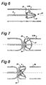
- a further embodiment is shown in Figures 6, 7 and 8.
- the cutting means 21 can be moved via a first neutral position which is shown in Figure 6, via a cutting position which is shown in Figure 7, into a second neutral position which is shown in Figure 8.
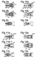
- FIGS 9a, 9b and 9c A further possible embodiment thereof is shown in Figures 9a, 9b and 9c.
- a first neutral position is shown in Figure 9a.
- the inner catheter element 91, to the end of which cutting elements 24 have been attached, has been pulled into the outer catheter element 90 to such an extent that the cutting elements are essentially enclosed by a covering 25 that at the end is joined to the outer catheter element 90.
- the cutting elements 24 are forced radially outwards.
- Figure 9b In the position shown in Figure 9b the cutting elements 24 will execute a cutting movement on the wall of the VSM 5, 5b. After executing this cutting operation, the cutting elements 24 can be pulled back into the covering 25 by pulling the inner catheter element 91 in the proximal direction relative to the outer catheter element 90.
- the various inner 91 and outer 90 catheter elements must be so constructed that the position of the cutting means (neutral or working position) at the distal end of the catheter elements must be recognisable from the proximal end of the catheter elements 90, 91.
- This means for example, that hand grips are arranged on the proximal end of the elements, the mutual position of the hand grips indicating the position of the cutting means.
- FIG. 10a, 10b and 10c show a catheter element where an inflatable element 26 is attached to the end thereof.
- a cutting element 24 is arranged in spiral form on the outer surface of the inflatable element 26.
- the inflatable element 26 can be inflated with the aid of a line that extends to the proximal section of the catheter element.
- the cutting elements or the cutting element 24 are/is forced radially outwards by this means. As a result a cutting movement can be executed on the wall of the VSM 5, 5b. After executing the cutting operation, the cutting means 24 can be moved back into a neutral position by allowing the inflatable element 26 to empty.
- FIG. 11a, 11b and 11c Something similar applies in the case of the embodiment which is shown in Figures 11a, 11b and 11c.
- the embodiment which is shown in Figures 11a, 11b and 11c also has an outer and an inner element 90 and 91, respectively.
- an inflatable element 26 which in this case is arranged between two or more cutting elements 24, said elements can be moved radially outwards, as is shown in Figure 11b, and during this movement execute a cutting operation.
- the inflatable element 26 can be emptied again, with the result that the cutting elements 24 will move inwards into the neutral position as is shown in Figure 11c.
- VSM is only removed from patients whose VSM is insufficient, it can suffice to exert a radial force on the wall of the VSM 5, 5b. This means that it can suffice to exert a radial force on the wall of the VSM with the aid of an inflatable element 26 which has no additional cutting elements arranged on the outside. This is shown in Figures 12a, 12b and 12c.
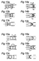
- Figure 13a shows a catheter element according to the present invention where the catheter element ends in a thickening or knob 50.
- Conducting means 51 are provided on the outside thereof.
- Conducting means 52 for example for conducting current, are provided in the catheter element 9.
- a current can be applied to the means 51 with the aid of the conducting means 52.
- the wall of the VSM can, as it were, be "burnt through” with the aid of this current. After the wall has been weakened or burnt through the catheter element 9 can be pulled out of the body in a manner corresponding to that already described above.
- Figure 14a shows a catheter element 9 which opens into an element 60 which has a slot or a channel 61 with sharp or cutting elements 62 at least on one side.
- a cutting movement can be executed on the wall of the VSM with the aid of the cutting edges 62 by exerting an axial force in the proximal direction. This is shown in Figure 14c.
- FIGs 16a, 16b and 16c It is also possible to make use of a memory metal.
- the catheter element can be brought into a position in the VSM shown in Figure 16a.
- the memory metal can be moved, for example under the action of heat, via a cutting intermediate position, as is shown in Figure 16b, into, for example, a second neutral position which is shown in Figure 16c.
- the cutting means 21 of each of the embodiments shown above either can be moved via a first neutral position into a cutting position and then into a second neutral position or can be moved via a first neutral position into a cutting position and then back into the first neutral position thereof.
Landscapes
- Health & Medical Sciences (AREA)
- Surgery (AREA)
- Life Sciences & Earth Sciences (AREA)
- Animal Behavior & Ethology (AREA)
- Public Health (AREA)
- Engineering & Computer Science (AREA)
- Biomedical Technology (AREA)
- Heart & Thoracic Surgery (AREA)
- Medical Informatics (AREA)
- Molecular Biology (AREA)
- Rheumatology (AREA)
- General Health & Medical Sciences (AREA)
- Nuclear Medicine, Radiotherapy & Molecular Imaging (AREA)
- Veterinary Medicine (AREA)
- Media Introduction/Drainage Providing Device (AREA)
- Magnetic Resonance Imaging Apparatus (AREA)
- Apparatuses For Bulk Treatment Of Fruits And Vegetables And Apparatuses For Preparing Feeds (AREA)
- Mechanical Treatment Of Semiconductor (AREA)
- Surgical Instruments (AREA)
- Saccharide Compounds (AREA)
- Acyclic And Carbocyclic Compounds In Medicinal Compositions (AREA)
Claims (14)
- Instrument zum Stripping einer Vene, umfassend ein Katheterelement (9), das ein erstes, oder proximales Ende und ein zweites, oder distales Ende hat, wobei das Katheterelement (9) an seinem distalen Ende ein Venenbefestigungsmittel hat, wobei das Venenbefestigungsmittel einen proximalen Teil hat, der an einen distalen Teil angrenzt, mit einer radialen äußeren Ausdehnung des distalen Teiles, die die entsprechende Ausdehnung des proximalen Teiles des Venenbefestigungsmittels überschreitet, so dass die Befestigung der Vene an dem Katheterelement (9) während der Perforation und/oder dem Schneiden der Vene und während des Stripping-Eingriffs mit Hilfe eines Drahtes ermöglicht wird, gekennzeichnet durch Schneidemittel (21) zum Perforieren und oder Schneiden der Vene von der Innenseite, wenn die Vene an dem Katheter (9) befestigt ist.
- Instrument gemäß Anspruch 1, dadurch gekennzeichnet, dass die Schneidemittel (21) zwischen einer ersten oder neutralen Stellung und einer zweiten oder Arbeitsstellung bewegbar sind.
- Instrument gemäß Anspruch 2, dadurch gekennzeichnet, dass das Katheterelement (9) mit Führungsmitteln (10, 25, 27) versehen ist, um die Schneidemittel (21) aus der ersten Stellung in die zweite Stellung zu führen.
- Instrument gemäß Anspruch 2 oder 3, dadurch gekennzeichnet, dass die Schneidemittel (21) einen Basiskörper (23) umfassen, der verschiebbar an dem Katheterelement (9) befestigt ist, wobei die Schneideelemente (24) gelenkartig mit besagtem Basiskörper (23) verbunden sind.
- Instrument gemäß Ansprüchen 3 und 4, dadurch gekennzeichnet, dass die Führungsmittel durch eine Verdickung (10) am distalen Ende des Katheterelementes (9) gebildet werden, wobei der Basiskörper (23) in axialer Richtung des Katheterelementes (9) aus der ersten Stellung zur zweiten Stellung bewegbar ist, wobei während dieser Bewegung die Verdickung zwischen die Schneideelemente (24) gedrängt wird, so dass die Schneideelemente (24) in Bezug auf das Katheterelement im Wesentlichen radial nach außen geführt werden.
- Instrument gemäß Anspruch 5, dadurch gekennzeichnet, dass die Schneidemittel (21) so angeordnet sind, dass sie in axialer Richtung zum distalen Ende des Katheterelementes (9) aus der zweiten Stellung in eine dritte Stellung beweg bar sind, wobei in der dritten Stellung die Verdickung (10) in einem Raum aufgenommen wird, der zwischen den Schneideelementen (24) und dem Basiskörper (23) gebildet wird.
- Instrument gemäß Anspruch 3 oder Anspruch 4 wenn auf Anspruch 3 Bezug genommen wird, dadurch gekennzeichnet, dass die Führungsmittel durch Hilfsarme (27) gebildet werden, welche gelenkartig am einen Ende mit dem distalen Ende der Schneideelemente (24) und am anderen Ende mit dem distalen Ende des Katheterelementes (9) verbunden sind.
- Instrument gemäß einem der vorhergehenden Ansprüche, wobei der äußere Durchmesse der Schneidemittel (21) den Durchmesser des Katheterelementes (9) übersteigt, um eine Verdickung bereitzustellen, so dass ein Zugelement, wie ein chirurgischer Draht (20), proximal von den Schneidemitteln (21) sicher befestigt werden kann zum Ausüben einer axialen Kraft auf die Schneidemittel (21) in Richtung des distalen Endes des Katheterelementes (9), um die Schneidemittel aus der ersten Stellung in Richtung auf die zweite Stellung zu bewegen.
- Instrument gemäß Anspruch 1, 2 oder 3, dadurch gekennzeichnet, dass das Katheterelement (9) einen inneren Katheterkörper (91) und einen äußeren Katheterkörper (90), der um den inneren Körper angeordnet ist, umfasst, wobei der innere Katheterkörper (91) in axialer Richtung bezüglich des äußeren Katheterkörpers (90) bewegbar ist, wobei der innere Katheterkörper (91) an seinem distalen Ende mit dem Schneidemittel, das ein oder mehr Schneideelemente (24) aufweist, versehen ist, und wobei der äußere Katheterkörper (90) an seinem distalen Ende mit Führungsmitteln (25) versehen ist und dadurch, dass der innere Körper (91) bezüglich des äußeren Körpers (90) aus einer ersten Stellung, in welcher die Schneideelemente (24) im Wesentlichen von den Führungsmitteln (25) eingeschlossen sind, bewegbar ist in eine zweite Stellung, in welcher die Schneideelemente (24) im Wesentlichen in radialer Richtung aus den Führungsmitteln (25) bewegt worden sind.
- Instrument gemäß Anspruch 1, 2 oder 3, dadurch gekennzeichnet, dass das Katheterelement (9) an seinem Ende mit Schneidemitteln versehen ist, die ein oder mehr Schneideelemente (24) aufweisen, wobei die besagten Schneideelemente auf beiden Seiten von oder auf einem aufblasbaren Körper befestigt sind, so dass die Schneideelemente durch Aufblasen des aufblasbaren Körpers (26) radial nach außen bewegt werden können.
- Instrument gemäß einem der vorhergehenden Ansprüche, dadurch gekennzeichnet, dass das Instrument eine Länge von vorzugsweise 600-1000 mm, insbesondere 600-750 mm und bevorzugter 600-700 mm aufweist.
- Kit, umfassend ein Instrument gemäß einem der vorhergehenden Ansprüche und einen chirurgischen Draht (20), welcher an seinem Ende mit einer bereits befestigten Schneidenadel versehen ist, wobei der Kit als Ganzes steril in einem Behälter verpackt ist.
- Kit gemäß Anspruch 12, dadurch gekennzeichnet, dass der Kit ferner ein chirurgisches Messer umfasst.
- Kit gemäß Anspruch 12 oder 13, dadurch gekennzeichnet, dass der chirurgische Draht (20) eine Länge von 1000-1600 mm, vorzugsweise 1200-1400 mm und am meisten bevorzugt 1300 mm aufweist.
Applications Claiming Priority (3)
| Application Number | Priority Date | Filing Date | Title |
|---|---|---|---|
| NL1011063A NL1011063C2 (nl) | 1999-01-19 | 1999-01-19 | Inrichting voor het strippen van venen. |
| NL1011063 | 1999-01-19 | ||
| PCT/NL2000/000039 WO2000042918A1 (en) | 1999-01-19 | 2000-01-19 | Device for stripping veins |
Publications (2)
| Publication Number | Publication Date |
|---|---|
| EP1146820A1 EP1146820A1 (de) | 2001-10-24 |
| EP1146820B1 true EP1146820B1 (de) | 2005-04-06 |
Family
ID=19768495
Family Applications (1)
| Application Number | Title | Priority Date | Filing Date |
|---|---|---|---|
| EP00903027A Expired - Lifetime EP1146820B1 (de) | 1999-01-19 | 2000-01-19 | Venenstripper |
Country Status (8)
| Country | Link |
|---|---|
| US (1) | US6652549B1 (de) |
| EP (1) | EP1146820B1 (de) |
| AT (1) | ATE292417T1 (de) |
| AU (1) | AU2466200A (de) |
| DE (1) | DE60019267T2 (de) |
| ES (1) | ES2239587T3 (de) |
| NL (1) | NL1011063C2 (de) |
| WO (1) | WO2000042918A1 (de) |
Families Citing this family (11)
| Publication number | Priority date | Publication date | Assignee | Title |
|---|---|---|---|---|
| US7163546B2 (en) * | 2001-12-21 | 2007-01-16 | Mirizzi Michael S | Method and apparatus for avulsion of varicose veins |
| BE1015315A3 (nl) | 2003-01-17 | 2005-01-11 | Inrichting en werkwijze voor het verwijderen van een bloedvat uit het menselijk lichaam. | |
| US8328797B2 (en) | 2004-12-23 | 2012-12-11 | C. R. Bard, Inc. | Blood vessel transecting and anastomosis |
| CA2721945C (en) | 2008-04-21 | 2015-11-24 | Axogen, Inc. | Nerve elevator and method of use |
| IE20090430A1 (en) | 2008-05-29 | 2010-03-03 | Embricon Ltd | A vein stripping device device |
| JP5377631B2 (ja) * | 2008-06-10 | 2013-12-25 | ババリア メディツイン テクノロジー ゲゼルシャフト ミット ベシュレンクテル ハフツング | 疾患心臓弁の治療用スコアリングカテーテル |
| CA2817442A1 (en) * | 2009-11-23 | 2011-05-26 | Nelson Medical Enterprises, Llc | Device and method for extracting tubular structures |
| US12471940B2 (en) | 2009-12-05 | 2025-11-18 | Pi-Cardia Ltd. | Fracturing calcifications in heart valves |
| US9636139B2 (en) * | 2012-12-12 | 2017-05-02 | Covidien Lp | Tissue-removing catheter with ball and socket deployment mechanism |
| WO2016027523A1 (ja) * | 2014-08-19 | 2016-02-25 | オリンパス株式会社 | 医療用処置具 |
| US10840776B2 (en) * | 2017-05-27 | 2020-11-17 | Actuator Electric Motors | Self-contained brushless motor and brushless controller |
Family Cites Families (12)
| Publication number | Priority date | Publication date | Assignee | Title |
|---|---|---|---|---|
| US3568677A (en) * | 1968-11-19 | 1971-03-09 | Brymill Corp | Surgical vein stripper |
| DE3400416A1 (de) * | 1983-10-01 | 1985-07-18 | Werner Dr.med. 4330 Mülheim Schubert | Teleoperationsgeraet in sonde/katheter |
| FR2635962B1 (fr) * | 1988-09-07 | 1990-10-12 | Trauchessec Jean Marc | Instrument chirurgical permettant les eveinages externes sans contre-perforation cutanee |
| US5320634A (en) * | 1990-07-03 | 1994-06-14 | Interventional Technologies, Inc. | Balloon catheter with seated cutting edges |
| US5242461A (en) * | 1991-07-22 | 1993-09-07 | Dow Corning Wright | Variable diameter rotating recanalization catheter and surgical method |
| US5224949A (en) * | 1992-01-13 | 1993-07-06 | Interventional Technologies, Inc. | Camming device |
| FR2717672A1 (fr) * | 1994-03-23 | 1995-09-29 | Dugast Herve | Instrument d'extraction de veine. |
| FR2727617B1 (fr) * | 1994-12-02 | 1997-04-30 | Lebard Christian | Dispositif d'eveinage pour realiser l'ablation d'une veine par invagination |
| US5667480A (en) * | 1995-10-20 | 1997-09-16 | Ethicon Endo-Surgery, Inc. | Method and devices for endoscopic vessel harvesting |
| US5843104A (en) * | 1995-11-21 | 1998-12-01 | Samuels; Peter B. | Method of removing blood vessels from the human body |
| WO1999039632A1 (en) * | 1998-02-06 | 1999-08-12 | Evans David K | Device for visualizing, dissecting and harvesting vessels |
| US6398798B2 (en) * | 1998-02-28 | 2002-06-04 | Lumend, Inc. | Catheter system for treating a vascular occlusion |
-
1999
- 1999-01-19 NL NL1011063A patent/NL1011063C2/nl not_active IP Right Cessation
-
2000
- 2000-01-19 EP EP00903027A patent/EP1146820B1/de not_active Expired - Lifetime
- 2000-01-19 WO PCT/NL2000/000039 patent/WO2000042918A1/en not_active Ceased
- 2000-01-19 AT AT00903027T patent/ATE292417T1/de not_active IP Right Cessation
- 2000-01-19 DE DE60019267T patent/DE60019267T2/de not_active Expired - Lifetime
- 2000-01-19 AU AU24662/00A patent/AU2466200A/en not_active Abandoned
- 2000-01-19 US US09/889,675 patent/US6652549B1/en not_active Expired - Fee Related
- 2000-01-19 ES ES00903027T patent/ES2239587T3/es not_active Expired - Lifetime
Also Published As
| Publication number | Publication date |
|---|---|
| EP1146820A1 (de) | 2001-10-24 |
| WO2000042918A1 (en) | 2000-07-27 |
| DE60019267T2 (de) | 2006-02-16 |
| ES2239587T3 (es) | 2005-10-01 |
| US6652549B1 (en) | 2003-11-25 |
| NL1011063C2 (nl) | 2000-07-24 |
| ATE292417T1 (de) | 2005-04-15 |
| DE60019267D1 (de) | 2005-05-12 |
| AU2466200A (en) | 2000-08-07 |
Similar Documents
| Publication | Publication Date | Title |
|---|---|---|
| US5797947A (en) | Methods and devices for harvesting blood vessels with balloons | |
| JP2677947B2 (ja) | 腹腔鏡を用いたヘルニア治療用の解剖学的腔を形成する装置及び方法及びこれに使用するパッチ | |
| US5702417A (en) | Balloon loaded dissecting instruments | |
| JP3914260B2 (ja) | 血管採取器具 | |
| US6712831B1 (en) | Methods and apparatus for forming anastomotic sites | |
| EP1098596B1 (de) | Speziell geformtes gerät zur verwendung in der chirurgie und verwendungsmethode | |
| US7850709B2 (en) | Blood vessel closure clip and delivery device | |
| US8840631B2 (en) | Compartment syndrome treatment method and surgical instrument for same | |
| US6679892B2 (en) | Surgical device for ligating and severing vessels | |
| US20040215233A1 (en) | Methods and apparatus for forming anastomotic sites | |
| JP2000508949A (ja) | 血管内バルーン閉塞装置及びその使用方法 | |
| JP4536306B2 (ja) | 視覚化を向上させたバルーン切開装置 | |
| US6551314B1 (en) | Methods and systems for vein harvesting | |
| EP1146820B1 (de) | Venenstripper | |
| JP2005534387A (ja) | 血管の穿刺孔をシールするための装置 | |
| JP2002513313A (ja) | バルーン切開装置 | |
| US7074220B2 (en) | Methods and systems for vein harvesting and fistula creation | |
| JP2007521032A (ja) | 吻合部位を形成するための方法および装置 | |
| JP3645912B2 (ja) | バルーン切開装置 | |
| WO2004049957A2 (en) | Apparatus and methods for minimally invasive harvesting of a vascular conduit | |
| EP1583474B1 (de) | Vorrichtung zur entfernung eines blutgefässes aus dem körper | |
| Petres et al. | Operative Treatment of Venous Disease |
Legal Events
| Date | Code | Title | Description |
|---|---|---|---|
| PUAI | Public reference made under article 153(3) epc to a published international application that has entered the european phase |
Free format text: ORIGINAL CODE: 0009012 |
|
| AK | Designated contracting states |
Kind code of ref document: A1 Designated state(s): AT BE CH CY DE DK ES FI FR GB GR IE IT LI LU MC NL PT SE |
|
| AX | Request for extension of the european patent |
Free format text: AL;LT;LV;MK;RO;SI |
|
| 17P | Request for examination filed |
Effective date: 20010816 |
|
| 17Q | First examination report despatched |
Effective date: 20030718 |
|
| GRAP | Despatch of communication of intention to grant a patent |
Free format text: ORIGINAL CODE: EPIDOSNIGR1 |
|
| GRAS | Grant fee paid |
Free format text: ORIGINAL CODE: EPIDOSNIGR3 |
|
| GRAA | (expected) grant |
Free format text: ORIGINAL CODE: 0009210 |
|
| AK | Designated contracting states |
Kind code of ref document: B1 Designated state(s): AT BE CH CY DE DK ES FI FR GB GR IE IT LI LU MC NL PT SE |
|
| PG25 | Lapsed in a contracting state [announced via postgrant information from national office to epo] |
Ref country code: FI Free format text: LAPSE BECAUSE OF FAILURE TO SUBMIT A TRANSLATION OF THE DESCRIPTION OR TO PAY THE FEE WITHIN THE PRESCRIBED TIME-LIMIT Effective date: 20050406 Ref country code: BE Free format text: LAPSE BECAUSE OF FAILURE TO SUBMIT A TRANSLATION OF THE DESCRIPTION OR TO PAY THE FEE WITHIN THE PRESCRIBED TIME-LIMIT Effective date: 20050406 Ref country code: AT Free format text: LAPSE BECAUSE OF FAILURE TO SUBMIT A TRANSLATION OF THE DESCRIPTION OR TO PAY THE FEE WITHIN THE PRESCRIBED TIME-LIMIT Effective date: 20050406 Ref country code: CH Free format text: LAPSE BECAUSE OF FAILURE TO SUBMIT A TRANSLATION OF THE DESCRIPTION OR TO PAY THE FEE WITHIN THE PRESCRIBED TIME-LIMIT Effective date: 20050406 Ref country code: LI Free format text: LAPSE BECAUSE OF FAILURE TO SUBMIT A TRANSLATION OF THE DESCRIPTION OR TO PAY THE FEE WITHIN THE PRESCRIBED TIME-LIMIT Effective date: 20050406 Ref country code: NL Free format text: LAPSE BECAUSE OF FAILURE TO SUBMIT A TRANSLATION OF THE DESCRIPTION OR TO PAY THE FEE WITHIN THE PRESCRIBED TIME-LIMIT Effective date: 20050406 |
|
| REG | Reference to a national code |
Ref country code: GB Ref legal event code: FG4D |
|
| REG | Reference to a national code |
Ref country code: CH Ref legal event code: EP |
|
| REG | Reference to a national code |
Ref country code: IE Ref legal event code: FG4D |
|
| REF | Corresponds to: |
Ref document number: 60019267 Country of ref document: DE Date of ref document: 20050512 Kind code of ref document: P |
|
| PG25 | Lapsed in a contracting state [announced via postgrant information from national office to epo] |
Ref country code: SE Free format text: LAPSE BECAUSE OF FAILURE TO SUBMIT A TRANSLATION OF THE DESCRIPTION OR TO PAY THE FEE WITHIN THE PRESCRIBED TIME-LIMIT Effective date: 20050706 Ref country code: DK Free format text: LAPSE BECAUSE OF FAILURE TO SUBMIT A TRANSLATION OF THE DESCRIPTION OR TO PAY THE FEE WITHIN THE PRESCRIBED TIME-LIMIT Effective date: 20050706 Ref country code: GR Free format text: LAPSE BECAUSE OF FAILURE TO SUBMIT A TRANSLATION OF THE DESCRIPTION OR TO PAY THE FEE WITHIN THE PRESCRIBED TIME-LIMIT Effective date: 20050706 |
|
| PG25 | Lapsed in a contracting state [announced via postgrant information from national office to epo] |
Ref country code: PT Free format text: LAPSE BECAUSE OF FAILURE TO SUBMIT A TRANSLATION OF THE DESCRIPTION OR TO PAY THE FEE WITHIN THE PRESCRIBED TIME-LIMIT Effective date: 20050908 |
|
| REG | Reference to a national code |
Ref country code: ES Ref legal event code: FG2A Ref document number: 2239587 Country of ref document: ES Kind code of ref document: T3 |
|
| NLV1 | Nl: lapsed or annulled due to failure to fulfill the requirements of art. 29p and 29m of the patents act | ||
| REG | Reference to a national code |
Ref country code: CH Ref legal event code: PL |
|
| PG25 | Lapsed in a contracting state [announced via postgrant information from national office to epo] |
Ref country code: IE Free format text: LAPSE BECAUSE OF NON-PAYMENT OF DUE FEES Effective date: 20060119 |
|
| PG25 | Lapsed in a contracting state [announced via postgrant information from national office to epo] |
Ref country code: LU Free format text: LAPSE BECAUSE OF NON-PAYMENT OF DUE FEES Effective date: 20060131 Ref country code: MC Free format text: LAPSE BECAUSE OF NON-PAYMENT OF DUE FEES Effective date: 20060131 |
|
| PLBE | No opposition filed within time limit |
Free format text: ORIGINAL CODE: 0009261 |
|
| STAA | Information on the status of an ep patent application or granted ep patent |
Free format text: STATUS: NO OPPOSITION FILED WITHIN TIME LIMIT |
|
| ET | Fr: translation filed | ||
| 26N | No opposition filed |
Effective date: 20060110 |
|
| REG | Reference to a national code |
Ref country code: IE Ref legal event code: MM4A |
|
| PGFP | Annual fee paid to national office [announced via postgrant information from national office to epo] |
Ref country code: ES Payment date: 20070130 Year of fee payment: 8 |
|
| PGFP | Annual fee paid to national office [announced via postgrant information from national office to epo] |
Ref country code: IT Payment date: 20070530 Year of fee payment: 8 |
|
| PGFP | Annual fee paid to national office [announced via postgrant information from national office to epo] |
Ref country code: FR Payment date: 20070109 Year of fee payment: 8 |
|
| PGFP | Annual fee paid to national office [announced via postgrant information from national office to epo] |
Ref country code: GB Payment date: 20080122 Year of fee payment: 9 |
|
| PG25 | Lapsed in a contracting state [announced via postgrant information from national office to epo] |
Ref country code: CY Free format text: LAPSE BECAUSE OF FAILURE TO SUBMIT A TRANSLATION OF THE DESCRIPTION OR TO PAY THE FEE WITHIN THE PRESCRIBED TIME-LIMIT Effective date: 20050406 |
|
| REG | Reference to a national code |
Ref country code: FR Ref legal event code: ST Effective date: 20081029 |
|
| REG | Reference to a national code |
Ref country code: ES Ref legal event code: FD2A Effective date: 20080121 |
|
| PG25 | Lapsed in a contracting state [announced via postgrant information from national office to epo] |
Ref country code: FR Free format text: LAPSE BECAUSE OF NON-PAYMENT OF DUE FEES Effective date: 20080131 |
|
| PG25 | Lapsed in a contracting state [announced via postgrant information from national office to epo] |
Ref country code: ES Free format text: LAPSE BECAUSE OF NON-PAYMENT OF DUE FEES Effective date: 20080121 |
|
| PG25 | Lapsed in a contracting state [announced via postgrant information from national office to epo] |
Ref country code: IT Free format text: LAPSE BECAUSE OF NON-PAYMENT OF DUE FEES Effective date: 20080119 |
|
| GBPC | Gb: european patent ceased through non-payment of renewal fee |
Effective date: 20090119 |
|
| PG25 | Lapsed in a contracting state [announced via postgrant information from national office to epo] |
Ref country code: GB Free format text: LAPSE BECAUSE OF NON-PAYMENT OF DUE FEES Effective date: 20090119 |
|
| PGFP | Annual fee paid to national office [announced via postgrant information from national office to epo] |
Ref country code: DE Payment date: 20110112 Year of fee payment: 12 |
|
| PG25 | Lapsed in a contracting state [announced via postgrant information from national office to epo] |
Ref country code: DE Free format text: LAPSE BECAUSE OF NON-PAYMENT OF DUE FEES Effective date: 20120801 |
|
| REG | Reference to a national code |
Ref country code: DE Ref legal event code: R119 Ref document number: 60019267 Country of ref document: DE Effective date: 20120801 |