EP1148168A2 - Sèche-linge domestique - Google Patents
Sèche-linge domestique Download PDFInfo
- Publication number
- EP1148168A2 EP1148168A2 EP01830214A EP01830214A EP1148168A2 EP 1148168 A2 EP1148168 A2 EP 1148168A2 EP 01830214 A EP01830214 A EP 01830214A EP 01830214 A EP01830214 A EP 01830214A EP 1148168 A2 EP1148168 A2 EP 1148168A2
- Authority
- EP
- European Patent Office
- Prior art keywords
- air
- compartment
- laundry dryer
- base
- laundry
- Prior art date
- Legal status (The legal status is an assumption and is not a legal conclusion. Google has not performed a legal analysis and makes no representation as to the accuracy of the status listed.)
- Withdrawn
Links
Images

Classifications
-
- D—TEXTILES; PAPER
- D06—TREATMENT OF TEXTILES OR THE LIKE; LAUNDERING; FLEXIBLE MATERIALS NOT OTHERWISE PROVIDED FOR
- D06F—LAUNDERING, DRYING, IRONING, PRESSING OR FOLDING TEXTILE ARTICLES
- D06F58/00—Domestic laundry dryers
- D06F58/10—Drying cabinets or drying chambers having heating or ventilating means
-
- D—TEXTILES; PAPER
- D06—TREATMENT OF TEXTILES OR THE LIKE; LAUNDERING; FLEXIBLE MATERIALS NOT OTHERWISE PROVIDED FOR
- D06F—LAUNDERING, DRYING, IRONING, PRESSING OR FOLDING TEXTILE ARTICLES
- D06F58/00—Domestic laundry dryers
- D06F58/20—General details of domestic laundry dryers
-
- D—TEXTILES; PAPER
- D06—TREATMENT OF TEXTILES OR THE LIKE; LAUNDERING; FLEXIBLE MATERIALS NOT OTHERWISE PROVIDED FOR
- D06F—LAUNDERING, DRYING, IRONING, PRESSING OR FOLDING TEXTILE ARTICLES
- D06F34/00—Details of control systems for washing machines, washer-dryers or laundry dryers
- D06F34/14—Arrangements for detecting or measuring specific parameters
- D06F34/26—Condition of the drying air, e.g. air humidity or temperature
Definitions
- the present invention relates to a mechanised laundry dryer, preferably, but non restrictively usable in the home environment.
- wash Home laundry, commonly known as wash, is washed manually or by means of automatic machines. After the washing phase, the wash needs, as is well known, a drying phase aimed at extracting water from the fibres of the fabrics, and to allow the washed clothes to be worn.
- Fabrics are dried: either naturally, in open environments with the combined effect of atmospheric agents, or with electromechanical laundry dryers located inside homes.
- the first category is that of rotating drum laundry dryers, so called because the wash to be dried is introduced into a suitably constructed metal drum which, by rotating with appropriate motion transmission means, exposes the wash contained therein to the drying action of suitably provided ventilated warm air.
- the rotation effect causes the wash to be uniformly exposed to the drying effect of the warm air, reducing drying time.
- the wash must be extracted from the drum and subjected to an ironing action, because the combined effect of rotation and rubbing has created, in individual laundry items, an anti-aesthetic creased effect on the fabric.
- This type of laundry dryer has rather high electrical power consumption. Moreover, the laundry is subjected to wear due to the successive and repeated drying operations and caused by the mutual rubbing of individual laundry items.
- the second category of laundry dryer is the one commonly called closet dryer.
- closet dryer In this type of laundry dryer, the entire wash is hung with of appropriate fastening means inside metal closets and dried with the aid of ventilated warm air that removes the water content from the laundry.
- the laundry thus hung is not deteriorated and undergoes only minor creasing effects, also because individual laundry items are subjected to a natural stretching effect that allows to eliminate or simplify the subsequent ironing operation.
- too air is heated by means of electrical resistors which cause high electrical consumption and which, during the drying process, tend to reduce the efficiency of the heat exchange because of the progressive saturation of air with the vapour from the water subtracted from the laundry being dried.
- the condensation that collects on the metal wall is then collected and evacuated outside the closet.
- the aim of the present invention is to overcome these drawbacks by means of a laundry dryer, according to the preamble to claim 1, in which the laundry to be dried is contained in a compartment connected in closed loop to means for the thermo-hygrometric treatment of the air and to mechanical circulation means, said treatment means creating in mutual combination a flow of air with controlled temperature and humidity which is then made to circulate repeatedly, in closed cycle, between the interior compartment of the closet and the thermo-hygrometric treatment means.
- Laundry dryers thus devised have high energy efficiency accompanied by very reduced electrical power consumption.
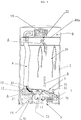
- the reference number 1 globally indicates a laundry dryer for home use 29, essentially comprising ( Figure 1) a load bearing structure 2, internally provided with a compartment 3 for containing the laundry 29 to be dried, and fitted with a hood 6 for aspirating the air and with an internally hollow base 7, embodied by a metal case 31.
- hood 6 and the base 7, which are positioned respectively one superiorly and one inferiorly to the compartment 3, are mutually connected by means of a tubular conduit 8 and are also connected directly to the compartment 3 itself with which they inter-communicate through suitable walls 18a, 18b constituted by holed grids.
- the drying compartment 3 can advantageously and economically be simply delimited peripherally by a closure case 17, positioned between the aspirating hood and the base 7 and made of deformable plastic material, with the conduit 8 also being made of deformable plastic material (see Figure 1).
- the laundry dryer 1 is provided with mechanical ventilation means 15, 16, with means for heating the air - globally indicated as 5 - and with means 12 for the hygrometric treatment of the air of the interior compartment 3 of the structure 2, included in the load bearing structure 2 and operatively connected in closed loop.
- a flow of air repeatedly circulates between the containment compartment 3, the hood 6, the conveyor 8, the means 12 for the hygrometric treatment of the air and the heating means 5, as indicated with arrows A.
- the hood 6 houses the first means for the mechanical ventilation of the air of the compartment 3, embodied by an aspirating fan 16 that draws the air from the underlying compartment 3 and mechanically accelerates it addressing it towards the tubular conduit 8.
- the base 7 is inferiorly provided with wheels 21 for supporting and transferring the laundry dryer 1 and contains within it the means 12 for the hygrometric treatment of the air of the drying compartment 3, as well as the means 13 for warming said air. All these means are preferably embodied by a same and single heat pump apparatus 9 operating between a section 10 for the inlet of air into the base 7 and a section 11 for the outlet of air from the basement 7, towards the drying compartment 3.
- the heat pump apparatus 9 ( Figure 2) essentially comprises an evaporator 12, a condenser 13 and a hermetic compressor 14 connected in a closed loop, within which evolves a refrigerating fluid.
- the evaporator 12 is associated to the air conduit 8 that connects the hood 6 with the base 7; the condenser 13 is associated instead to the section 11 for the outlet of air from the base 7, towards the drying compartment 3.
- the heat pump apparatus 9 also comprises control means 22; 24, 23 for respectively controlling the water content in the air and the maximum operating temperature of the positive displacement blower 14.
- the means for controlling the water content present in the air are preferably located in the hood 6, before the aspirating fan 16 (said means, being wholly conventional, are only symbolically shown in the drawings).
- the control means that instead control the maximum temperature of the positive displacement blower 14 are located in the base 7 and are preferably embodied by a temperature sensor 24 and by a by-pass valve 23, commanded by the sensor 24 and positioned in parallel to the positive displacement blower 14 between the related intake section 25 and delivery section 26 of the refrigerating fluid.
- second ventilation means 15 embodied by a pusher fan 15 that aspirates the flow of air from the evaporator 12 and thrusts it, accelerating it, towards the interior of the drying compartment 3, to travel through the condenser 13.
- the base 7 further contains a tray 19 for collecting the condensate of the evaporator 12 and is provided with an openable door 20 for the extraction of the tray 19.
- the laundry 29 to be dried is hung inside the compartment 3 with appropriate fastening means 30.
- the warm air required to extract water from the fabrics is heated and dehumidified inside the base 7 by the heat pump apparatus contained therein.
- the related compressor 14 aspirates the refrigerating liquid in the vapour state contained in the related circuit, compresses, boosting its pressure and temperature, and sends it towards the condenser 13.
- the superheated refrigerating vapour enters the upper part of the condenser 13, releases the heat it contained, and condenses to the state of warm liquid.
- the refrigerating fluid in the warm liquid state moves from the condenser 13 towards the evaporator 12.
- the air for cooling the condenser 13 is blown by the pusher fan 15.
- the air that exits the grid 18b has a temperature above that of the air in the home environment, since it has increased its temperature by removing heat from the hermetic compressor 14, the pusher fan 15 and the condenser 13.
- An outlet temperature of the air of approximately 45-50°C is thereby obtained without using electrical resistors to heat the air.
- the air at the outlet of the condenser 13 and through the grid filtering element 18b, rises with velocity, blowing by the laundry 29 hung in the compartment 3 of the laundry dryer 1; it is enriched with water particles contained in the fibres of the fabrics and is aspirated, through the upper grid filtering element 18b.
- the moist air drops with velocity and pressure through the tubular conduit 8, into the base 7 of the laundry dryer wherein it comes in contact with the cold surface of the evaporator 12.
- the water content of the air which traverses the cold wall of the evaporator 12, condenses on its surface in the form of droplets.
- the control means 22 verify the water content in the recirculating air and, below predefined values of relative humidity of the recirculating air, disconnect electrical power to the fan 16 or 15 or to the hermetic compressor 14.
- the compressor 14 reaches a high temperature.
- the temperature sensor 24 placed in contact with the outer case of the hermetic compressor 14 detects this temperature.
- the temperature sensor 24, appropriately calibrated opens the by-pass valve 23 that connects the intake section 25 and the delivery section 26 of the refrigerating vapour. In this way, the electrical power absorbed by the internal motor of the hermetic compressor 14 decreases, the hermetic compressor 14 cools and hence the appropriately calibrated temperature sensor 24 closes the by-pass valve 23.
Landscapes
- Engineering & Computer Science (AREA)
- Textile Engineering (AREA)
- Drying Of Solid Materials (AREA)
- Detail Structures Of Washing Machines And Dryers (AREA)
- Washing And Drying Of Tableware (AREA)
Applications Claiming Priority (2)
| Application Number | Priority Date | Filing Date | Title |
|---|---|---|---|
| IT2000RN000017A ITRN20000017A1 (it) | 2000-04-18 | 2000-04-18 | Asciugabiancheria domestico meccanizzato. |
| ITRN000017 | 2000-04-18 |
Publications (2)
| Publication Number | Publication Date |
|---|---|
| EP1148168A2 true EP1148168A2 (fr) | 2001-10-24 |
| EP1148168A3 EP1148168A3 (fr) | 2003-02-19 |
Family
ID=11456595
Family Applications (1)
| Application Number | Title | Priority Date | Filing Date |
|---|---|---|---|
| EP01830214A Withdrawn EP1148168A3 (fr) | 2000-04-18 | 2001-03-29 | Sèche-linge domestique |
Country Status (2)
| Country | Link |
|---|---|
| EP (1) | EP1148168A3 (fr) |
| IT (1) | ITRN20000017A1 (fr) |
Cited By (4)
| Publication number | Priority date | Publication date | Assignee | Title |
|---|---|---|---|---|
| WO2006067819A1 (fr) * | 2004-12-22 | 2006-06-29 | Italtecno Consulting Srl | Dispositif de sechage du linge |
| CN109137426A (zh) * | 2017-06-28 | 2019-01-04 | 北京天然天启科技有限公司 | 衣物烘干机构 |
| CN110295489A (zh) * | 2019-06-25 | 2019-10-01 | 熊文 | 一种干衣机 |
| US20210310179A1 (en) * | 2018-08-20 | 2021-10-07 | Samsung Electronics Co., Ltd. | Clothes care apparatus |
Family Cites Families (4)
| Publication number | Priority date | Publication date | Assignee | Title |
|---|---|---|---|---|
| SE421327B (sv) * | 1975-10-15 | 1981-12-14 | Henning Brinch Madsen | Aggregat for torkning av tvett |
| IT1154032B (it) * | 1981-03-09 | 1987-01-21 | Carlo Meda | Essiccatore particolarmente asciuga biancheria dotato di un circuito frigorifero fungente da pompa di calore |
| JPH04156896A (ja) * | 1990-10-19 | 1992-05-29 | Matsushita Electric Ind Co Ltd | 除湿型乾燥機 |
| JPH04259497A (ja) * | 1991-02-13 | 1992-09-16 | Matsushita Electric Ind Co Ltd | 除湿型乾燥機 |
-
2000
- 2000-04-18 IT IT2000RN000017A patent/ITRN20000017A1/it unknown
-
2001
- 2001-03-29 EP EP01830214A patent/EP1148168A3/fr not_active Withdrawn
Cited By (5)
| Publication number | Priority date | Publication date | Assignee | Title |
|---|---|---|---|---|
| WO2006067819A1 (fr) * | 2004-12-22 | 2006-06-29 | Italtecno Consulting Srl | Dispositif de sechage du linge |
| CN109137426A (zh) * | 2017-06-28 | 2019-01-04 | 北京天然天启科技有限公司 | 衣物烘干机构 |
| US20210310179A1 (en) * | 2018-08-20 | 2021-10-07 | Samsung Electronics Co., Ltd. | Clothes care apparatus |
| US12203207B2 (en) * | 2018-08-20 | 2025-01-21 | Samsung Electronics Co., Ltd. | Clothes care apparatus |
| CN110295489A (zh) * | 2019-06-25 | 2019-10-01 | 熊文 | 一种干衣机 |
Also Published As
| Publication number | Publication date |
|---|---|
| EP1148168A3 (fr) | 2003-02-19 |
| ITRN20000017A1 (it) | 2001-10-18 |
Similar Documents
| Publication | Publication Date | Title |
|---|---|---|
| ES2396452T3 (es) | Máquina para secar la ropa que comprende una reserva de agua de condensación que alimenta un dispositivo de limpieza de un intercambiador de calor y un generador de vapor | |
| EP0094356B1 (fr) | Séchoir, en particulier une armoire sèche-linge | |
| CA2049529A1 (fr) | Secheuse a linge | |
| JP2009106566A (ja) | 洗濯乾燥機及び乾燥機 | |
| US10597815B2 (en) | Laundry treatment apparatus | |
| WO2019233548A1 (fr) | Sèche-linge | |
| CN103221606B (zh) | 用于去除洗衣干衣机内的洗涤物中的有气味物质的方法以及适用于所述方法的洗衣干衣机 | |
| EP3309292A1 (fr) | Système de traitement de filtre pour un appareil de blanchissage à pompe thermique | |
| KR20170024265A (ko) | 건조기 | |
| JP2010035894A (ja) | ドラム式洗濯乾燥機 | |
| JP2003275497A (ja) | 空気循環路を有する家電機器または衣類乾燥機または洗濯乾燥機 | |
| TW201727004A (zh) | 烘乾機及洗衣烘乾機 | |
| KR100826204B1 (ko) | 건조기 | |
| US20040255394A1 (en) | Spin cycle methodology and article drying apparatus | |
| EP1148168A2 (fr) | Sèche-linge domestique | |
| EP2123823B1 (fr) | Séchoir à linge pour usage domestique | |
| US3050975A (en) | Laundry machine with suction means for removing moisture | |
| JP2008284071A (ja) | 洗濯乾燥機 | |
| EP2620540B1 (fr) | Machine pour sécher le linge | |
| CN114672964A (zh) | 一种具有4d微蒸渗透黑科技的衣物护理机 | |
| CN112244682B (zh) | 一种排水装置和烘手机 | |
| KR101314625B1 (ko) | 의류처리장치 | |
| GB2215826A (en) | Laundry drier with droplet removal | |
| KR100723992B1 (ko) | 대류 건조기 | |
| JP4361964B1 (ja) | 洗濯乾燥機 |
Legal Events
| Date | Code | Title | Description |
|---|---|---|---|
| PUAI | Public reference made under article 153(3) epc to a published international application that has entered the european phase |
Free format text: ORIGINAL CODE: 0009012 |
|
| AK | Designated contracting states |
Kind code of ref document: A2 Designated state(s): AT BE CH CY DE DK ES FI FR GB GR IE IT LI LU MC NL PT SE TR |
|
| AX | Request for extension of the european patent |
Free format text: AL;LT;LV;MK;RO;SI |
|
| PUAL | Search report despatched |
Free format text: ORIGINAL CODE: 0009013 |
|
| RIC1 | Information provided on ipc code assigned before grant |
Ipc: 7D 06F 58/24 B Ipc: 7D 06F 58/10 B Ipc: 7D 06F 58/20 A |
|
| AK | Designated contracting states |
Designated state(s): AT BE CH CY DE DK ES FI FR GB GR IE IT LI LU MC NL PT SE TR |
|
| AX | Request for extension of the european patent |
Extension state: AL LT LV MK RO SI |
|
| AKX | Designation fees paid | ||
| REG | Reference to a national code |
Ref country code: DE Ref legal event code: 8566 |
|
| STAA | Information on the status of an ep patent application or granted ep patent |
Free format text: STATUS: THE APPLICATION IS DEEMED TO BE WITHDRAWN |
|
| 18D | Application deemed to be withdrawn |
Effective date: 20030820 |