EP0094356B1 - Séchoir, en particulier une armoire sèche-linge - Google Patents
Séchoir, en particulier une armoire sèche-linge Download PDFInfo
- Publication number
- EP0094356B1 EP0094356B1 EP83830088A EP83830088A EP0094356B1 EP 0094356 B1 EP0094356 B1 EP 0094356B1 EP 83830088 A EP83830088 A EP 83830088A EP 83830088 A EP83830088 A EP 83830088A EP 0094356 B1 EP0094356 B1 EP 0094356B1
- Authority
- EP
- European Patent Office
- Prior art keywords
- air
- passage
- cooling passage
- inlet
- drying chamber
- Prior art date
- Legal status (The legal status is an assumption and is not a legal conclusion. Google has not performed a legal analysis and makes no representation as to the accuracy of the status listed.)
- Expired
Links
- 238000001035 drying Methods 0.000 title claims description 41
- 238000001816 cooling Methods 0.000 claims description 42
- 238000010438 heat treatment Methods 0.000 claims description 22
- XLYOFNOQVPJJNP-UHFFFAOYSA-N water Substances O XLYOFNOQVPJJNP-UHFFFAOYSA-N 0.000 claims description 12
- 238000005057 refrigeration Methods 0.000 description 3
- 230000006835 compression Effects 0.000 description 2
- 238000007906 compression Methods 0.000 description 2
- 238000009833 condensation Methods 0.000 description 2
- 230000005494 condensation Effects 0.000 description 2
- 230000000694 effects Effects 0.000 description 2
- 239000012530 fluid Substances 0.000 description 2
- 239000002184 metal Substances 0.000 description 2
- 229920006395 saturated elastomer Polymers 0.000 description 2
- 241000208125 Nicotiana Species 0.000 description 1
- 235000002637 Nicotiana tabacum Nutrition 0.000 description 1
- 238000007664 blowing Methods 0.000 description 1
- 239000004020 conductor Substances 0.000 description 1
- 238000007791 dehumidification Methods 0.000 description 1
- 235000013399 edible fruits Nutrition 0.000 description 1
- 238000005265 energy consumption Methods 0.000 description 1
- 239000004744 fabric Substances 0.000 description 1
- 239000000463 material Substances 0.000 description 1
- 238000013021 overheating Methods 0.000 description 1
- 239000003507 refrigerant Substances 0.000 description 1
- 230000001105 regulatory effect Effects 0.000 description 1
- 229920002994 synthetic fiber Polymers 0.000 description 1
Images
Classifications
-
- D—TEXTILES; PAPER
- D06—TREATMENT OF TEXTILES OR THE LIKE; LAUNDERING; FLEXIBLE MATERIALS NOT OTHERWISE PROVIDED FOR
- D06F—LAUNDERING, DRYING, IRONING, PRESSING OR FOLDING TEXTILE ARTICLES
- D06F58/00—Domestic laundry dryers
- D06F58/10—Drying cabinets or drying chambers having heating or ventilating means
-
- D—TEXTILES; PAPER
- D06—TREATMENT OF TEXTILES OR THE LIKE; LAUNDERING; FLEXIBLE MATERIALS NOT OTHERWISE PROVIDED FOR
- D06F—LAUNDERING, DRYING, IRONING, PRESSING OR FOLDING TEXTILE ARTICLES
- D06F58/00—Domestic laundry dryers
- D06F58/20—General details of domestic laundry dryers
- D06F58/206—Heat pump arrangements
-
- D—TEXTILES; PAPER
- D06—TREATMENT OF TEXTILES OR THE LIKE; LAUNDERING; FLEXIBLE MATERIALS NOT OTHERWISE PROVIDED FOR
- D06F—LAUNDERING, DRYING, IRONING, PRESSING OR FOLDING TEXTILE ARTICLES
- D06F58/00—Domestic laundry dryers
- D06F58/20—General details of domestic laundry dryers
Definitions
- the present invention relates to driers specially designed for household use as clothes-drying cabinets but which can be used equally well for drying various types of industrial articles.
- Driers for household use of many different types are already known; we will refer here to some of the known machines only, which exemplify the prior art.
- the British Patent No. 1133098 discloses a drying apparatus comprising an air heating chamber, an air cooling chamber and a drying chamber.
- An air duct is situated underneath the chambers and connects the drying chamber to the heating chamber;
- a compression refrigeration system is mounted within the drier, the compressor being contained within the duct, the condenser in the heating chamber and the evaporator in the cooling chamber;
- a V-shaped trough positioned directly below the evaporator cooperates with a drain pipe to collect and dispose of water condensed from the air in the cooling chamber; a fan forces air from the duct into the heating chamber.
- a drier comprising a cabinet with rods to append the clothes to be dried; in the bottom of the cabinet there is a heating apparatus; outside the cabinet there is a compression refrigeration system; the evaporator is located inside a condensation chamber; a fan on the top of the cabinet forces all the air into the condensation chamber; at the bottom of the cabinet there is provided a hole to allow external air to enter the cabinet.
- the U.S.A. Patent No. 3064358 describes a clothes drying device in which blowers circulate filtered air past an evaporator, an expansion valve, and a condenser coil trough which a refrigerant is conveyed by means of a compressor unit, and forcing the dry air into a perforated enclosure in which a revolving cylinder supporting the clothes is disposed.
- the enclosure shows inlet openings which may be closed by dampers controlled by pressure responsive linkages.
- a drier apparatus comprising an enclosure which contains a drying chamber for receiving articles to be dried, an air heating passage and an air cooling passage communicating with said chamber wherein the heating passage has inlet means and outlet means communicating therewith, air heating means being provided in the heating passage between the inlet and the outlet means thereof to heat air flowing through said heating passage, and wherein the cooling passage has inlet means through which the top of the drying chamber communicates with the top of the cooling passage and outlet means at the bottom of the cooling passage, air cooling means being provided in the cooling passage between the inlet and outlet means thereof, to condense moisture from air flowing in the cooling passage, and water collecting means being provided underneath the outlet means of the cooling passage to collect the water dripping from the cooling means, the arrangement being such that a major air flow is circulated between the drying chamber and the heating passage and a minor air flow is circulated from the drying chamber to the cooling passage.
- This arrangement provides for a relatively low loss in sensible heat in the damp air so that the refrigerating circuit condenser required relatively little energy to compensate for the sensible heat absorbed by the evaporator or a cold wall in the cooling passage.
- the drawback on this known type of drier is that the efficiency of the cooling circuit gradually falls off as the drying cycle proceeds. The reason for this is that, as the cycle proceeds, the difference in temperature between the evaporator and the condenser gradually becomes smaller on account of a gradual increase in the temperature of the air recirculated along the cooling passage. Under such conditions, besides a gradual increase in the energy consumption of the compressor, the entire refrigerating circuit may even rise to unacceptable temperatures. On the one hand, this could damage the refrigerating system and, on the other, the temperature in the drying chamber could rise high enough to damage delicate fabrics such as synthetic fibres, silk and the like.
- the aim of the present invention is to provide a drier of the described type, not showing the drawbacks of the prior art machines.
- this aim is achieved with a drying unit having the characteristics recited in the main claim.
- This arrangement provides for drying cycles with lower, more uniform refrigeration circuit pressures and temperatures than would be possible if the unit operated with no communication with the outside air. Supposing for example, as is usually the case, that the temperature in the room where the drier is installed does not vary during the drying cycle. This means there will be no substantial variation in the temperature difference with which heat is exchanged between the air and the refrigerating fluid on the condenser and evaporator. In other words, air pumped in from outside acts as a sort of "brake" on the rise in temperature and the temperature differences in the refrigerating circuit.
- a further advantage of the unit according to the present invention is that it also uses the heat content of the outside air.
- Supposing the unit e.g. a clothes-drier, is installed in a room with an air temperature of 20°C, 60% relative humidity and air containing 8.73 gr of water per kilo.
- the heat content of the air will be 10.10 kcal/kg (42.2 kJ/kg).
- the unit is designed so that air is blown off into the atmosphere, through the cooling passage, at 12°C with 100% relative humidity, with the same 8.73 gr of water per kilo, its heat content will be 8.10 kcal/kg (33.8 kJ/kg).
- the air pumped in from the outside will supply 2 kcal/kg with consequent saving in energy.
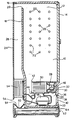
- the unit shown in the drawing is in the form of a cabinet with a casing of sheet metal or other suitable material.
- the casing contains a drying chamber 10 defined by side walls 12, a front door 14, a top 16 and rear dividing wall 18. Walls 12 and 18, top 16 and front door 14 are all lagged.
- rear dividing wall 18 does not extend as far as top 16.
- the edge of dividing wall 18, together with top 16, defines a horizontal slot 20.
- Drying chamber 10 is fitted inside with hooks and rails on which to hang clothes or other items, an arrangement that turns the unit into a household clothes-drying cabinet.
- drying chamber 10 may be fitted with grate shelves for drying items other than clothes, e.g. photographs, tobacco leaves, fruit, etc.
- the casing has a rear or outside wall 24 which, together with dividing wall 18, forms a space 26 which, as we shall explain later, acts as a cooling passage.
- Rear wall 24 is made of sheet metal or other heat-conducting material to act as a cooling means by exchanging heat with the outside air. For even better heat exchange performance, wall 24 may be fitted with fins.
- the bottom 28 of drying chamber 10 is fitted over another bottom panel 30 so as to form a space 32 which, as we shall see later, acts as a passage for heating and air circulation.
- the casing or cabinet has yet another horizontal structural panel 33 under bottom panel 30 which, together with the latter, forms a bottom compartment 34. The latter is defined at the front by wall 36 and at the rear by a bottom extension of dividing wall 18. For reasons explained later, compartment 34 communicates with the outside air through opening 38 (e.g. a slit) in wall 36 fitted with a grate 40.
- heating and circulating passage 32 communicates with both the bottom of chamber 10 and compartment 34.
- the through openings, preferably slits, are marked 42 and 44.
- passage 32 communicates with the bottom of chamber 10 with circulating means in the form of an electric blower in- between.
- the casing or cabinet has a built-in refrigerating circuit which acts as a heat pump and comprises a known hermetic electric compressor 48, a condenser 50, a trottling element 52 and an evaporator 54.
- the hermetic compressor 48 is a normal household refrigerator type situated in compartment 34 and secured to structural wall 33.
- the trottling element 52 is preferably a capillary tube.
- Condenser 50 is in the form of a box heat exchanger which extends right across the heating and circulating passage 32.
- Evaporator 54 consists of a box heat exchanger, very similar to heat exchanger 50, situated at the bottom of cooling passage 26 and extending right across it.
- Under exchanger-evaporator 54 in rear wall 24 is an opening (preferably a slit) 56 through which cooling passage 26 communicates with the outside air.
- a receptacle 58 in the form of a gutter which, through drain opening 60, leads to a drip tank or box 62 under structural wall 32.
- Box 62 slides inside the cabinet for collecting condensed water formed, as we shall see, in cooling passage 26 and exchanger-evaporator 54 during operation of the unit. Condensed water dripping into receptacle 58 is collected in box 62 which can be pulled out of the cabinet.
- Box 62 is preferably fitted with a transparent (e.g. plastic) front wall so the level of water can be seen for emptying the box periodically.
- receptacle 58 can be connected directly to a water drain.
- the drier described and shown in the drawing operates as follows:
- Electric blower 46 circulates the air in a closed circuit, sucking it up from chamber 10 through opening 42, sending it through condenser 50 and blowing it out into the bottom of chamber 10. At the same time, electric blower 46 sucks up air from the outside through opening 38, compartment 34 and opening 44. When it passes into compartment 34, the air sucked up from the outside flows over the casing of compressor 48, cooling the latter and being heated by it. The air sucked up from the outside also flows through exchanger-condenser 50 and is blown into the bottom of chamber 10 by blower 46. The air circulating in chamber 10 and heated gradually in exchanger-condenser 50 becomes saturated with humidity. The hottest air containing most humidity forms a layer or "dome" at the top of chamber 10 which traps in the heat to improve the efficiency of the unit.
- the air current flowing down into passage 26 is caused by the difference in pressure between the inside of chamber 10 and the outside air as well as by the "reverse drawing” effect created in space 26 by the increasing density of the air as it is cooled.
- the cooled air is then exhausted to the outside through opening 56.
- the size of air inlets 38 and 56 and circulation passages 26 and 32 and the power of air circulating means 46 and heat exchangers 50 and 54 are designed so that the air circulating inside the casing is such that the air flowing over evaporator 54 and condenser 50 is automatically less at the end of the drying cycle than at the beginning.
- Operation of the unit is regulated automatically: as the drying cycle proceeds, the temperature of the air in chamber 10 rises while its relative humidity falls. Consequently there is also a fall in the specific weight of the air, in the socalled "reverse drawing” effect and the amount of air exhausted to the outside.
- the latter case is an advantage as far as the evaporator is concerned in that it receives less and less heat from the air thus preventing any unwanted rise in temperature. What is more, the smaller the amount of air being supplied to the evaporator, the easier it is to cool down to the dew point which provides for better dehumidification.
- blower 46 provides yet another advantage: the load loss in cooling passage 26 creates a certain pressure in chamber 10 which makes the air in the chamber less flexible, so to speak, thus preventing it from finding its own way out through slit 20. This ensures all parts of chamber 10 are swept more or less evenly so as to dry the clothes or other items in the chamber more uniformly.
- condenser 50 in circulation passage 32 could be replaced entirely or in part by a coil pipe in drying chamber 10 in the form of horizontal bars on which to hang clothes or other items.
- a further variation of the specific arrangement described could be to fit the outside air inlet 38 and outlet 56 with temporary shutters, e.g. controlled by a timer on the unit, which provide for operating the cabinet under airtight conditions during the intermediate drying stage.
Landscapes
- Engineering & Computer Science (AREA)
- Textile Engineering (AREA)
- Drying Of Solid Materials (AREA)
- Detail Structures Of Washing Machines And Dryers (AREA)
Claims (4)
Applications Claiming Priority (2)
| Application Number | Priority Date | Filing Date | Title |
|---|---|---|---|
| IT6760882 | 1982-05-10 | ||
| IT67608/82A IT1155193B (it) | 1982-05-10 | 1982-05-10 | Apparecchio essicatore particolarmente armadio asciugabiancheria |
Publications (2)
| Publication Number | Publication Date |
|---|---|
| EP0094356A1 EP0094356A1 (fr) | 1983-11-16 |
| EP0094356B1 true EP0094356B1 (fr) | 1986-07-02 |
Family
ID=11303834
Family Applications (1)
| Application Number | Title | Priority Date | Filing Date |
|---|---|---|---|
| EP83830088A Expired EP0094356B1 (fr) | 1982-05-10 | 1983-05-03 | Séchoir, en particulier une armoire sèche-linge |
Country Status (3)
| Country | Link |
|---|---|
| EP (1) | EP0094356B1 (fr) |
| DE (1) | DE3364365D1 (fr) |
| IT (1) | IT1155193B (fr) |
Families Citing this family (24)
| Publication number | Priority date | Publication date | Assignee | Title |
|---|---|---|---|---|
| US5152077A (en) * | 1991-08-16 | 1992-10-06 | Liang Chao Jung | Cloth drying machine |
| AU648333B2 (en) * | 1991-08-21 | 1994-04-21 | Chao-Jung Liang | Clothes drying machine |
| AU1249292A (en) * | 1992-01-13 | 1993-08-03 | Jwi, Inc. | Batch-type sludge drier |
| GB2289752A (en) * | 1994-05-23 | 1995-11-29 | Acma Thermal Research Pte Ltd | Clothes dryer |
| EP1146161A1 (fr) * | 2000-04-10 | 2001-10-17 | Whirlpool Corporation | Accessoire pour sèche-linge à tambour |
| EP1294908B1 (fr) | 2000-06-28 | 2006-03-08 | Max-Delbrück-Centrum Für Molekulare Medizin | Procede permettant d'ameliorer le rendement de transfection |
| DE10030531B4 (de) * | 2000-06-28 | 2004-08-26 | Multitroc Patentverwertungsgesellschaft Mbh & Co.Kg | Verfahren und Vorrichtung zur bügelfreien Trocknung von feuchtem Gut, insbesondere von feuchter Wäsche bzw. Kleidung |
| EP1501975B1 (fr) * | 2002-03-01 | 2006-12-06 | Ayla Cevik | Procede et appareil de repassage automatique |
| GB2394271B (en) * | 2002-10-18 | 2005-07-13 | Nikolaos Kanavas | A locker for drying clothing |
| US7191546B2 (en) | 2004-06-18 | 2007-03-20 | Maruca Robert E | Low temperature clothes dryer |
| ITVR20050063A1 (it) * | 2004-11-25 | 2006-05-26 | Eko S P A | Tavolo da stiro e dispositivo erogatore di vapore |
| ES2368431T3 (es) | 2004-12-06 | 2011-11-17 | Lg Electronics Inc. | Secador de ropa. |
| JP4783125B2 (ja) * | 2005-11-17 | 2011-09-28 | 株式会社東芝 | 衣類乾燥機 |
| KR101265605B1 (ko) * | 2006-07-04 | 2013-05-22 | 엘지전자 주식회사 | 의류 처리 장치 |
| JP4388088B2 (ja) * | 2007-02-16 | 2009-12-24 | 株式会社東芝 | 衣類乾燥機 |
| DE102008054104A1 (de) * | 2008-10-31 | 2010-05-06 | Herbert Kannegiesser Gmbh | Verfahren und Vorrichtung zum Aufbereiten der Abluft von beheizten Wäschereimaschinen |
| US8528227B2 (en) * | 2010-07-26 | 2013-09-10 | General Electric Company | Apparatus and method for refrigerant cycle capacity acceleration |
| US8353114B2 (en) | 2010-07-26 | 2013-01-15 | General Electric Company | Apparatus and method for refrigeration cycle with auxiliary heating |
| US8601717B2 (en) | 2010-07-26 | 2013-12-10 | General Electric Company | Apparatus and method for refrigeration cycle capacity enhancement |
| CN102926178A (zh) * | 2012-11-29 | 2013-02-13 | 惠而浦(中国)投资有限公司 | 冷凝式干衣机及干衣方法 |
| CN104631070A (zh) * | 2013-11-07 | 2015-05-20 | 杭州三花研究院有限公司 | 干衣机 |
| CN104532525B (zh) * | 2014-11-28 | 2017-01-25 | 浙江普林艾尔电器工业有限公司 | 一种热泵干衣柜及其设计制作方法 |
| CN105544162A (zh) * | 2015-12-04 | 2016-05-04 | 无锡小天鹅股份有限公司 | 洗干一体机 |
| CN105862371B (zh) * | 2016-05-26 | 2019-11-22 | 无锡小天鹅电器有限公司 | 干衣机和干衣机的控制方法 |
Citations (1)
| Publication number | Priority date | Publication date | Assignee | Title |
|---|---|---|---|---|
| EP0060226A1 (fr) * | 1981-03-09 | 1982-09-15 | INDESIT INDUSTRIA ELETTRODOMESTICI ITALIANA S.p.A. | Appareil de séchage |
Family Cites Families (10)
| Publication number | Priority date | Publication date | Assignee | Title |
|---|---|---|---|---|
| US3064358A (en) * | 1958-02-17 | 1962-11-20 | Anthony A Giuffre | Clothes drying device |
| FR1370792A (fr) * | 1963-05-02 | 1964-08-28 | Séchoir à linge à condenseur frigorifique | |
| FR1390083A (fr) * | 1964-04-23 | 1965-02-19 | Armoire sèche-linge | |
| GB1133098A (en) * | 1964-11-20 | 1968-11-06 | John Edward Randell | Improvements in and relating to drying apparatus |
| FR1439185A (fr) * | 1965-04-07 | 1966-05-20 | Armoire sèche-linge à circuit fermé | |
| FR1458677A (fr) * | 1965-10-01 | 1966-03-04 | Georges Deoust Ets | Séchoir à linge |
| FR1542480A (fr) * | 1966-03-23 | 1900-01-01 | Dispositif pour le séchage accéléré d'objets | |
| FR1562056A (fr) * | 1968-01-22 | 1969-04-04 | ||
| FR1598605A (fr) * | 1968-12-13 | 1970-07-06 | ||
| DE2218440C2 (de) * | 1972-04-17 | 1974-03-21 | Wilhelm Dr.-Ing. 5340 Bad Honnef Lepper | Verfahren zum Trocknen von Wäsche od. dgl. und Vorrichtung zur Durchführung des Verfahrens |
-
1982
- 1982-05-10 IT IT67608/82A patent/IT1155193B/it active
-
1983
- 1983-05-03 EP EP83830088A patent/EP0094356B1/fr not_active Expired
- 1983-05-03 DE DE8383830088T patent/DE3364365D1/de not_active Expired
Patent Citations (1)
| Publication number | Priority date | Publication date | Assignee | Title |
|---|---|---|---|---|
| EP0060226A1 (fr) * | 1981-03-09 | 1982-09-15 | INDESIT INDUSTRIA ELETTRODOMESTICI ITALIANA S.p.A. | Appareil de séchage |
Also Published As
| Publication number | Publication date |
|---|---|
| IT1155193B (it) | 1987-01-21 |
| EP0094356A1 (fr) | 1983-11-16 |
| DE3364365D1 (en) | 1986-08-07 |
| IT8267608A0 (it) | 1982-05-10 |
Similar Documents
| Publication | Publication Date | Title |
|---|---|---|
| EP0094356B1 (fr) | Séchoir, en particulier une armoire sèche-linge | |
| US7377052B2 (en) | Low temperature clothes dryer | |
| US4471537A (en) | Dryer apparatus having an improved air circulation | |
| US5152077A (en) | Cloth drying machine | |
| EP0197132B1 (fr) | Secheur comprenant une pompe a chaleur | |
| US3739487A (en) | Drying apparatus | |
| US9249538B2 (en) | Laundry treatment apparatus with heat pump | |
| RU2626952C2 (ru) | Сушильная машина | |
| EP2573253B1 (fr) | Sèche-linge à pompe à chaleur | |
| GB2094961A (en) | Drying apparatus | |
| KR102372507B1 (ko) | 건조기 | |
| EP2549007B1 (fr) | Appareil de traitement de linge à pompe thermique | |
| US2521081A (en) | Drier | |
| KR100407908B1 (ko) | 냉각 건조 옷장 | |
| EP0060226B1 (fr) | Appareil de séchage | |
| US2660806A (en) | Clothes drying system | |
| KR20130024715A (ko) | 에너지 절약형 김 건조기 | |
| EP3450615B1 (fr) | Séchoir et procédé de production d'un séchoir | |
| KR100741801B1 (ko) | 에어컨 시스템의 응축열을 이용한 건조기 및 이를 구비한에어컨 시스템 | |
| CN211233676U (zh) | 一种家庭式烘干除湿机风道系统 | |
| KR101373027B1 (ko) | 김 건조기 | |
| JPH1076100A (ja) | 衣類乾燥機 | |
| KR200237179Y1 (ko) | 냉각 건조 옷장 | |
| EP1148168A2 (fr) | Sèche-linge domestique | |
| SU741626A1 (ru) | Сушилка дл м сных и колбасных изделий |
Legal Events
| Date | Code | Title | Description |
|---|---|---|---|
| PUAI | Public reference made under article 153(3) epc to a published international application that has entered the european phase |
Free format text: ORIGINAL CODE: 0009012 |
|
| AK | Designated contracting states |
Designated state(s): DE FR GB NL SE |
|
| 17P | Request for examination filed |
Effective date: 19840316 |
|
| GRAA | (expected) grant |
Free format text: ORIGINAL CODE: 0009210 |
|
| AK | Designated contracting states |
Kind code of ref document: B1 Designated state(s): DE FR GB NL SE |
|
| REF | Corresponds to: |
Ref document number: 3364365 Country of ref document: DE Date of ref document: 19860807 |
|
| ET | Fr: translation filed | ||
| PLBE | No opposition filed within time limit |
Free format text: ORIGINAL CODE: 0009261 |
|
| STAA | Information on the status of an ep patent application or granted ep patent |
Free format text: STATUS: NO OPPOSITION FILED WITHIN TIME LIMIT |
|
| 26N | No opposition filed | ||
| PGFP | Annual fee paid to national office [announced via postgrant information from national office to epo] |
Ref country code: SE Payment date: 19890411 Year of fee payment: 7 |
|
| PGFP | Annual fee paid to national office [announced via postgrant information from national office to epo] |
Ref country code: GB Payment date: 19890430 Year of fee payment: 7 |
|
| PGFP | Annual fee paid to national office [announced via postgrant information from national office to epo] |
Ref country code: DE Payment date: 19890502 Year of fee payment: 7 |
|
| PGFP | Annual fee paid to national office [announced via postgrant information from national office to epo] |
Ref country code: NL Payment date: 19890531 Year of fee payment: 7 Ref country code: FR Payment date: 19890531 Year of fee payment: 7 |
|
| PG25 | Lapsed in a contracting state [announced via postgrant information from national office to epo] |
Ref country code: GB Effective date: 19900503 |
|
| PG25 | Lapsed in a contracting state [announced via postgrant information from national office to epo] |
Ref country code: SE Effective date: 19900504 |
|
| PG25 | Lapsed in a contracting state [announced via postgrant information from national office to epo] |
Ref country code: NL Effective date: 19901201 |
|
| GBPC | Gb: european patent ceased through non-payment of renewal fee | ||
| NLV4 | Nl: lapsed or anulled due to non-payment of the annual fee | ||
| PG25 | Lapsed in a contracting state [announced via postgrant information from national office to epo] |
Ref country code: FR Effective date: 19910131 |
|
| PG25 | Lapsed in a contracting state [announced via postgrant information from national office to epo] |
Ref country code: DE Effective date: 19910201 |
|
| REG | Reference to a national code |
Ref country code: FR Ref legal event code: ST |
|
| EUG | Se: european patent has lapsed |
Ref document number: 83830088.7 Effective date: 19910115 |