EP1148247A2 - Montage d'un rotor par matage ou soudage par points - Google Patents
Montage d'un rotor par matage ou soudage par points Download PDFInfo
- Publication number
- EP1148247A2 EP1148247A2 EP00122396A EP00122396A EP1148247A2 EP 1148247 A2 EP1148247 A2 EP 1148247A2 EP 00122396 A EP00122396 A EP 00122396A EP 00122396 A EP00122396 A EP 00122396A EP 1148247 A2 EP1148247 A2 EP 1148247A2
- Authority
- EP
- European Patent Office
- Prior art keywords
- motor yoke
- shaft
- motor
- central portion
- fan
- Prior art date
- Legal status (The legal status is an assumption and is not a legal conclusion. Google has not performed a legal analysis and makes no representation as to the accuracy of the status listed.)
- Granted
Links
- 238000003466 welding Methods 0.000 title claims description 6
- XEEYBQQBJWHFJM-UHFFFAOYSA-N Iron Chemical group [Fe] XEEYBQQBJWHFJM-UHFFFAOYSA-N 0.000 claims description 11
- 238000000034 method Methods 0.000 claims description 3
- 238000010276 construction Methods 0.000 description 5
- 238000004512 die casting Methods 0.000 description 5
- WABPQHHGFIMREM-UHFFFAOYSA-N lead(0) Chemical compound [Pb] WABPQHHGFIMREM-UHFFFAOYSA-N 0.000 description 5
- 238000004804 winding Methods 0.000 description 5
- 230000004907 flux Effects 0.000 description 2
- 229920003002 synthetic resin Polymers 0.000 description 2
- 239000000057 synthetic resin Substances 0.000 description 2
- 238000005266 casting Methods 0.000 description 1
- 230000003993 interaction Effects 0.000 description 1
- 238000004519 manufacturing process Methods 0.000 description 1
- 230000003685 thermal hair damage Effects 0.000 description 1
- 238000009423 ventilation Methods 0.000 description 1
Images



Classifications
-
- F—MECHANICAL ENGINEERING; LIGHTING; HEATING; WEAPONS; BLASTING
- F04—POSITIVE - DISPLACEMENT MACHINES FOR LIQUIDS; PUMPS FOR LIQUIDS OR ELASTIC FLUIDS
- F04D—NON-POSITIVE-DISPLACEMENT PUMPS
- F04D25/00—Pumping installations or systems
- F04D25/02—Units comprising pumps and their driving means
- F04D25/08—Units comprising pumps and their driving means the working fluid being air, e.g. for ventilation
-
- F—MECHANICAL ENGINEERING; LIGHTING; HEATING; WEAPONS; BLASTING
- F04—POSITIVE - DISPLACEMENT MACHINES FOR LIQUIDS; PUMPS FOR LIQUIDS OR ELASTIC FLUIDS
- F04D—NON-POSITIVE-DISPLACEMENT PUMPS
- F04D25/00—Pumping installations or systems
- F04D25/02—Units comprising pumps and their driving means
- F04D25/06—Units comprising pumps and their driving means the pump being electrically driven
- F04D25/0606—Units comprising pumps and their driving means the pump being electrically driven the electric motor being specially adapted for integration in the pump
-
- F—MECHANICAL ENGINEERING; LIGHTING; HEATING; WEAPONS; BLASTING
- F04—POSITIVE - DISPLACEMENT MACHINES FOR LIQUIDS; PUMPS FOR LIQUIDS OR ELASTIC FLUIDS
- F04D—NON-POSITIVE-DISPLACEMENT PUMPS
- F04D29/00—Details, component parts, or accessories
- F04D29/26—Rotors specially for elastic fluids
- F04D29/263—Rotors specially for elastic fluids mounting fan or blower rotors on shafts
-
- Y—GENERAL TAGGING OF NEW TECHNOLOGICAL DEVELOPMENTS; GENERAL TAGGING OF CROSS-SECTIONAL TECHNOLOGIES SPANNING OVER SEVERAL SECTIONS OF THE IPC; TECHNICAL SUBJECTS COVERED BY FORMER USPC CROSS-REFERENCE ART COLLECTIONS [XRACs] AND DIGESTS
- Y10—TECHNICAL SUBJECTS COVERED BY FORMER USPC
- Y10T—TECHNICAL SUBJECTS COVERED BY FORMER US CLASSIFICATION
- Y10T29/00—Metal working
- Y10T29/49—Method of mechanical manufacture
- Y10T29/49826—Assembling or joining
- Y10T29/49908—Joining by deforming
- Y10T29/49938—Radially expanding part in cavity, aperture, or hollow body
Definitions
- the present invention relates to the improvement of a fan and a motor yoke mounting method for a fan to be used in the O.A. (Office automation) equipment of various types.
- O.A. Office automation
- O.A. equipment of various types accommodates a large number of electronic circuits in its housing, so that the heat generated by electronic components forming those electronic circuits is difficult to be expelled therefrom, and some electronic components may be broken or deteriorated.
- the equipment is miniaturized without considerable reduction of the generated heat, and accordingly the countermeasure against heat is required as an important technical solution. Therefore, a ventilating hole is provided on the side wall of the equipment and a fan is fixed therein to expel the internal heat out of the equipment, thereby eliminating the thermal damage occurred inside.
- Reference numeral 1 designates a casing that has a cylindrical shape.
- a housing 2 is integrally formed to a central portion of this casing 1.
- a cylindrical bearing liner 3 is fitted in a central portion of the housing 2.
- Outer races of bearings 4 and 5 are supported on the inner side of this bearing liner 3, and inner races of the bearings 4 and 5 support a shaft 6 having an equal diameter at two axial locations.
- a ring 7 is mounted on a lower end of the shaft 6 to prevent removal of the shaft 6 as well as to position the shaft 6 axially.
- Reference numeral 8 designates an impeller that is made of synthetic resin to have blades 10 on the outer periphery of the main body 9.
- the main body 9 of this impeller 8 is fitted onto a cup-shaped motor yoke 11.
- the motor yoke 11 is fitted to the upper end of the shaft 6 through a zinc-die-casting boss 12. Further, the upper end of the shaft 6 is formed with a knurl 13 to enhance the adhesion of the boss 12 thereto when the boss 12 molded.
- An annular magnet 14 is adhesively fixed to an inner periphery of the motor yoke 11 to form a rotary section.
- a stator iron core 16 on which a stator winding 15 is provided is disposed on the outer side of bearing liner 3 and fixed to the bearing liner 3 to form a stator section.
- a PC board 17 which forms an electronic circuit as a brush-less motor with electronic components is mounted on the lower portion of the stator iron core 16. The electronic circuit incorporated in this PC board 17 controls current supplied to rotate the rotary section relative to the stator section.
- a lead wire not shown, connects the stator winding 15 to the electronic circuit incorporated in the PC board 17.
- a lead wire 18 is connected to the PC board 17 to supply electric power to the PC board 17.
- the fan of such construction is used by being mounted on a ventilating hole of the housing of the O.A. equipment.
- the fan is mounted in such a manner as the upper portion thereof in Fig. 9 is directed outward the housing of the O.A. equipment and so that the shaft 6 extends horizontally.
- the current controlled by the control circuit in the PC board 17 flows to the stator winding 15, so that the rotary section is rotated by a magnetic interaction between a magnetic flux caused on the stator iron core 16 and a magnetic flux generated by the magnet 14.
- the rotation of the impeller 8 absorbs the air inside the housing in the lower side of the drawing, to direct and expel the air out of the housing into the direction which is indicated as upward in the drawing. This air ventilation cools the interior of the housing.
- the aforementioned conventional fan has such a complicated construction that the motor yoke 11 is mounted on the shaft 6 through the boss 12 made by zinc-die-casting, and thus there was a tendency that the motor yoke 11 was mounted under inconstant force.
- the motor components are miniaturized, because of such complicated mounting structure, there was such a problem that the mounting force of the motor 11 was not stabilized.
- the zinc-die-casting causes a cost increase.
- an object of the present invention is to provide a fan in which a motor yoke can be mounted on a shaft with a simple construction and securely, and a mounting force of the motor yoke can be stabilized, in particular when the motor components are miniaturized, and also, a reduction of the manufacturing cost can be achieved.
- the fan device is characterized in that a stepped portion defining a smaller diameter on an end face side is provided on one end portion of the shaft; and the motor yoke is mounted to the shaft portion in such a manner that the central portion of the motor yoke is fitted to the stepped portion by press-fitting, and the motor yoke thus fitted by the press-fitting is fixed to the stepped portion by caulking, thereby completing the mounting of the motor yoke on the shaft.
- a bearing is disposed on a central portion of a cylindrical casing, a motor yoke is mounted to a shaft supported by the bearing, and a stator iron core is disposed inside the motor yoke.
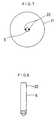
- the fan is characterized in that the shaft has an equal diameter on one end portion thereof and the motor yoke is mounted on the shaft in such a manner as the central portion of the motor yoke is fitted to the one end portion by press-fitting, and the motor yoke thus fitted by press-fitting is fixed to the one end portion by spot welding thereby the mounting of the motor yoke to the shaft is completed.
- the shaft can be directly mounted on the central portion of the motor yoke without using the boss made by zinc-die-casting as in the conventional style. Consequently, it is possible to obtain a fan that is simple in construction, stable in strength, and low in cost.
- Reference numeral 1 designates a casing that has a cylindrical shape.
- a housing 2 is formed integrally with a central portion of this casing 1.
- a cylindrical bearing liner 3 is fitted in a central portion of the housing 2.
- Outer races of bearings 4 and 5 are supported on the inner side of the bearing liner 3, and inner races of the bearings 4 and 5 support a shaft 6 at two points.
- a ring 7 is mounted on a lower end of the shaft 6 to prevent the shaft 6 from pulling out and to position the shaft 6 in an axial direction.
- Reference numeral 8 designates an impeller that is made of synthetic resin to have a cylindrical main body 9 and blades 10 on the outer periphery of the main body 9.
- the main body 9 of this impeller 8 is fitted and fixed on an outer periphery of a cup-shaped motor yoke 11. As shown in a portion A in Fig. 2 and Fig. 3, the shaft 6 is directly inserted and fitted to a central portion of this motor yoke 11.
- the shaft 6 is formed at the upper end of Fig. 4 in a stepped portion 19 defining a slightly smaller diameter. Furthermore, the shaft 6 is provided with a funnel-shaped recess 20 in the central portion of the upper end face.
- the motor yoke 11 is then mounted on the stepped portion 19 of the shaft 6 in such a manner as the central portion of the above motor yoke 11 is fitted by press-fitting, and the pressure-fitted motor yoke 11 is fixed to the above stepped portion 19 by caulking thereby, the mounting of the motor yoke 11 on the shaft 6 is completed.
- the tip end (i.e. the lower end in Fig. 2 and 4) of the above recess 20 is coincident in location with a central axis of the shaft 6, and the shape of the recess 20 is symmetric with respect to the central axis, so that this recess 20 is used for a guide and centering at the time of fixing by caulking.
- every reference numeral 21 in the drawings denotes caulking fixed portions.
- an annular magnet 14 is fixed in adhesion to an inner periphery of the above motor yoke 11 to form a rotary section.
- a stator iron core 16 on which a stator winding 15 is provided is disposed on the outer side of the bearing liner 3 and fixed thereto to form a stator section.
- Mounted on the lower portion of the stator iron core 16 is a PC board 17 which forms an electronic circuit as a brush-less motor by electronic components.
- the electronic circuit incorporated in this PC board 17 controls current supplied to rotate the rotary section relative to the stator section.
- a lead wire not shown, connects the stator winding 15 to the electronic circuit incorporated in the PC board 17. Furthermore, a lead wire 18 is connected to the PC board 17 to supply electric power to the PC board 17.
- an upper end portion 22 of the shaft 6 is dimensioned to have an equal diameter.
- the motor yoke 11 is mounted on the shaft 6 in such a manner that the motor yoke 11 is press-fitted to the upper end portion 22 of the shaft 6 thus constructed, and then the press-fitted motor yoke 11 is fixed to the upper end portion 22 by spot welding.
- reference numeral 23 designates each one of the fixed portions by spot welding.
- the fan described above is of an axial flow fan motor type, but the present invention should not be limited thereto and can be widely applied to a blower and so on.
Landscapes
- Engineering & Computer Science (AREA)
- Mechanical Engineering (AREA)
- General Engineering & Computer Science (AREA)
- Connection Of Motors, Electrical Generators, Mechanical Devices, And The Like (AREA)
- Structures Of Non-Positive Displacement Pumps (AREA)
- Motor Or Generator Frames (AREA)
- Iron Core Of Rotating Electric Machines (AREA)
Applications Claiming Priority (2)
| Application Number | Priority Date | Filing Date | Title |
|---|---|---|---|
| JP2000117889 | 2000-04-19 | ||
| JP2000117889A JP2001304199A (ja) | 2000-04-19 | 2000-04-19 | 送風機 |
Publications (3)
| Publication Number | Publication Date |
|---|---|
| EP1148247A2 true EP1148247A2 (fr) | 2001-10-24 |
| EP1148247A3 EP1148247A3 (fr) | 2002-11-06 |
| EP1148247B1 EP1148247B1 (fr) | 2006-03-22 |
Family
ID=18629131
Family Applications (1)
| Application Number | Title | Priority Date | Filing Date |
|---|---|---|---|
| EP00122396A Expired - Lifetime EP1148247B1 (fr) | 2000-04-19 | 2000-10-26 | Montage d'un rotor par matage ou soudage par points |
Country Status (6)
| Country | Link |
|---|---|
| US (2) | US6511299B1 (fr) |
| EP (1) | EP1148247B1 (fr) |
| JP (1) | JP2001304199A (fr) |
| CN (3) | CN1293690C (fr) |
| DE (1) | DE60026770T2 (fr) |
| TW (1) | TWM290654U (fr) |
Cited By (1)
| Publication number | Priority date | Publication date | Assignee | Title |
|---|---|---|---|---|
| IT201600074487A1 (it) * | 2016-07-15 | 2018-01-15 | Spal Automotive Srl | Ventilatore assiale. |
Families Citing this family (13)
| Publication number | Priority date | Publication date | Assignee | Title |
|---|---|---|---|---|
| JP2001140791A (ja) * | 1999-11-19 | 2001-05-22 | Minebea Co Ltd | ブロワー |
| JP2001304199A (ja) * | 2000-04-19 | 2001-10-31 | Minebea Co Ltd | 送風機 |
| US20040120833A1 (en) * | 2002-12-24 | 2004-06-24 | Hsieh Hsin Mao | Mini fan mounting arrangement |
| JP4620527B2 (ja) * | 2005-06-03 | 2011-01-26 | 株式会社日立製作所 | パケット通信装置 |
| CN101600321B (zh) * | 2008-06-04 | 2011-12-28 | 富准精密工业(深圳)有限公司 | 散热风扇及采用该散热风扇的电子装置 |
| JP2011032923A (ja) * | 2009-07-31 | 2011-02-17 | Yamada Seisakusho Co Ltd | ウォータポンプ |
| CN101895173B (zh) * | 2010-08-03 | 2012-07-18 | 宁波狮球通风机电有限公司 | 压轴用工装 |
| JP5708932B2 (ja) * | 2011-07-29 | 2015-04-30 | ミネベア株式会社 | ブラシレスモータ、アウターロータ型ブラシレスモータ及び送風機 |
| JP6097926B2 (ja) * | 2012-10-31 | 2017-03-22 | パナソニックIpマネジメント株式会社 | ブレード及びそれを用いた送風装置及び電子機器 |
| JP6937156B2 (ja) * | 2017-04-06 | 2021-09-22 | ツインバード工業株式会社 | 扇風機 |
| JP2019115208A (ja) * | 2017-12-25 | 2019-07-11 | 株式会社デンソー | ファン駆動装置 |
| DE102020104076A1 (de) * | 2020-02-17 | 2021-08-19 | Progress-Werk Oberkirch Aktiengesellschaft | Verfahren zum festen Verbinden einer Welle mit einem Rotorgehäuseteil sowie Rotorgehäuseteil |
| DE102022130321A1 (de) * | 2022-11-16 | 2024-05-16 | Ebm-Papst Mulfingen Gmbh & Co. Kg | Rotor und Verfahren zur Herstellung des Rotors |
Family Cites Families (36)
| Publication number | Priority date | Publication date | Assignee | Title |
|---|---|---|---|---|
| DE2100663A1 (de) * | 1971-01-08 | 1972-07-20 | Papst Motoren Kg | Elektrische Maschine, insbesondere Kleinstmotor |
| JPS5137366A (en) * | 1974-09-26 | 1976-03-29 | Aisin Seiki | Rootaatoshafuto no koteihoho |
| US4429245A (en) * | 1980-11-19 | 1984-01-31 | Papst Motoren Gmbh & Co., Kg | External rotor production for synchronous hysteresis motor |
| DE3144447A1 (de) | 1980-11-19 | 1982-07-08 | Papst-Motoren GmbH & Co KG, 7742 St Georgen | Aussenlaeuferkleinmotor und verfahren zur herstellung eines rotortopfes fuer einen solchen motor |
| JPS59145396A (ja) * | 1982-11-09 | 1984-08-20 | パプスト・モ−ト−レン・ゲ−エムベ−ハ−・ウント・コ−・カ−ゲ− | 直流小形通風機 |
| US5135363A (en) * | 1982-11-09 | 1992-08-04 | Papst-Motoren Gmbh & Co. Kg | Miniaturized direct current fan |
| US5267842A (en) * | 1982-11-09 | 1993-12-07 | Papst Licensing Gmbh | Miniaturized direct current fan |
| JPS60234149A (ja) * | 1984-05-07 | 1985-11-20 | Pioneer Electronic Corp | テ−プレコ−ダ用フライホイ−ル |
| US4620139A (en) * | 1985-07-22 | 1986-10-28 | Kabushiki Kaisha Shicoh Giken | Brushless d.c. motor |
| US4806081A (en) * | 1986-11-10 | 1989-02-21 | Papst-Motoren Gmbh And Company Kg | Miniature axial fan |
| JPS6281458U (fr) * | 1985-11-07 | 1987-05-25 | ||
| GB2185074B (en) * | 1985-11-08 | 1990-12-19 | Papst Motoren Gmbh & Co Kg | Fan |
| JPS62199222U (fr) * | 1986-06-04 | 1987-12-18 | ||
| JPH087820Y2 (ja) * | 1986-07-18 | 1996-03-04 | 三菱電機株式会社 | 送風機 |
| DE3871480D1 (de) | 1987-10-01 | 1992-07-02 | Seiko Electronic Components | Axialluefter. |
| JPH0192599A (ja) * | 1987-10-01 | 1989-04-11 | Seiko Electronic Components Ltd | 軸流ファンモータの構造 |
| JPH0749800B2 (ja) | 1988-03-11 | 1995-05-31 | 三菱電機株式会社 | 軸流送風機 |
| JPH0713416Y2 (ja) * | 1988-11-07 | 1995-03-29 | ソニー株式会社 | 軸流ファンモータ |
| US5519270A (en) * | 1992-08-19 | 1996-05-21 | Fujitsu Limited | Spindle motor and disk drive having the same |
| JP3365899B2 (ja) * | 1996-01-30 | 2003-01-14 | ミネベア株式会社 | モータ構造 |
| JP2879206B2 (ja) * | 1996-02-19 | 1999-04-05 | ミネベア株式会社 | 軸流ファンモータ |
| US6205110B1 (en) * | 1997-06-25 | 2001-03-20 | Nidec Corporation | Disk drive motor |
| JP3295842B2 (ja) * | 1998-07-16 | 2002-06-24 | ミネベア株式会社 | 軸流ファンモータ |
| US6050785A (en) * | 1998-11-04 | 2000-04-18 | Sunonwealth Electric Machine Industry Co., Ltd. | Axle balance plates for miniature heat dissipating fan assemblies |
| JP3255133B2 (ja) * | 1999-01-07 | 2002-02-12 | 松下電器産業株式会社 | Dcブラシレスファン |
| JP2000209832A (ja) * | 1999-01-12 | 2000-07-28 | Minebea Co Ltd | 軸流ファンモ―タ |
| JP2001140791A (ja) * | 1999-11-19 | 2001-05-22 | Minebea Co Ltd | ブロワー |
| JP2001186741A (ja) * | 1999-12-24 | 2001-07-06 | Minebea Co Ltd | 送風機 |
| JP3401640B2 (ja) * | 2000-02-29 | 2003-04-28 | ミネベア株式会社 | 送風機及びその製造方法 |
| JP3525088B2 (ja) * | 2000-03-14 | 2004-05-10 | ミネベア株式会社 | 送風機 |
| JP2001304199A (ja) * | 2000-04-19 | 2001-10-31 | Minebea Co Ltd | 送風機 |
| JP3482373B2 (ja) * | 2000-04-28 | 2003-12-22 | ミネベア株式会社 | 送風機 |
| JP2002039091A (ja) * | 2000-07-21 | 2002-02-06 | Minebea Co Ltd | 送風機 |
| US6703738B2 (en) * | 2000-11-29 | 2004-03-09 | Kokusan Denki Co., Ltd. | Outer rotor type brushless motor |
| JP2002247828A (ja) * | 2001-02-21 | 2002-08-30 | Canon Inc | スピンドルモータ |
| US6488483B1 (en) * | 2001-06-14 | 2002-12-03 | Hsieh Hsin-Mao | Low power loss heat dissipation fan |
-
2000
- 2000-04-19 JP JP2000117889A patent/JP2001304199A/ja active Pending
- 2000-10-21 TW TW094219579U patent/TWM290654U/zh not_active IP Right Cessation
- 2000-10-23 US US09/694,006 patent/US6511299B1/en not_active Expired - Fee Related
- 2000-10-26 DE DE60026770T patent/DE60026770T2/de not_active Expired - Lifetime
- 2000-10-26 EP EP00122396A patent/EP1148247B1/fr not_active Expired - Lifetime
- 2000-11-23 CN CNB2004100983907A patent/CN1293690C/zh not_active Expired - Fee Related
- 2000-11-23 CN CN200410098391.1A patent/CN1288825C/zh not_active Expired - Fee Related
- 2000-11-23 CN CN00128442.8A patent/CN1204343C/zh not_active Expired - Fee Related
-
2002
- 2002-10-15 US US10/269,887 patent/US6786706B2/en not_active Expired - Lifetime
Cited By (2)
| Publication number | Priority date | Publication date | Assignee | Title |
|---|---|---|---|---|
| IT201600074487A1 (it) * | 2016-07-15 | 2018-01-15 | Spal Automotive Srl | Ventilatore assiale. |
| WO2018011764A1 (fr) * | 2016-07-15 | 2018-01-18 | Spal Automotive S.R.L. | Ventilateur axial |
Also Published As
| Publication number | Publication date |
|---|---|
| HK1078689A1 (en) | 2006-03-17 |
| DE60026770D1 (de) | 2006-05-11 |
| US20030039560A1 (en) | 2003-02-27 |
| CN1293690C (zh) | 2007-01-03 |
| CN1625023A (zh) | 2005-06-08 |
| CN1288825C (zh) | 2006-12-06 |
| CN1318697A (zh) | 2001-10-24 |
| US6786706B2 (en) | 2004-09-07 |
| HK1079348A1 (en) | 2006-03-31 |
| EP1148247B1 (fr) | 2006-03-22 |
| EP1148247A3 (fr) | 2002-11-06 |
| DE60026770T2 (de) | 2006-09-07 |
| TWM290654U (en) | 2006-05-11 |
| JP2001304199A (ja) | 2001-10-31 |
| CN1204343C (zh) | 2005-06-01 |
| US6511299B1 (en) | 2003-01-28 |
| CN1625021A (zh) | 2005-06-08 |
Similar Documents
| Publication | Publication Date | Title |
|---|---|---|
| US6511299B1 (en) | Fan in which motor yoke is mounted by caulking or spot welding and the mounting method thereof | |
| US6447272B2 (en) | Blower | |
| US6278207B1 (en) | Blower | |
| US5925948A (en) | Axial flow fan motor | |
| US6196802B1 (en) | Axial flow fan | |
| US6368081B1 (en) | Blower | |
| CN106877563B (zh) | 驱动装置和鼓风机装置 | |
| EP1130270A2 (fr) | Ventilateur et sa méthode de construction | |
| US20070178720A1 (en) | Electric Fan | |
| JP4705122B2 (ja) | モータおよび送風ファン | |
| US20060153677A1 (en) | Mini fan | |
| US6023113A (en) | Axial flow fan motor | |
| CN210053260U (zh) | 马达 | |
| US20040027016A1 (en) | Electric machine | |
| US20100008800A1 (en) | Cooling fan unit and method for drawing out lead wires thereof | |
| US6655918B2 (en) | Impeller of axial-flow blower | |
| JP4051681B2 (ja) | 軸流ファンモータ | |
| JPH09285075A (ja) | 軸流ファンモータ | |
| JP2009250158A (ja) | 送風ファン | |
| JP2022045045A (ja) | 遠心ファン | |
| US20200309191A1 (en) | Gas dynamic pressure bearing, motor, and fan motor | |
| JP2000209809A (ja) | 軸流ファンモ―タ | |
| CN118202155A (zh) | 风扇及其制造方法 | |
| JP2019062672A (ja) | モータ | |
| JP2010156224A (ja) | 電動ポンプ |
Legal Events
| Date | Code | Title | Description |
|---|---|---|---|
| PUAI | Public reference made under article 153(3) epc to a published international application that has entered the european phase |
Free format text: ORIGINAL CODE: 0009012 |
|
| AK | Designated contracting states |
Kind code of ref document: A2 Designated state(s): AT BE CH CY DE DK ES FI FR GB GR IE IT LI LU MC NL PT SE |
|
| AX | Request for extension of the european patent |
Free format text: AL;LT;LV;MK;RO;SI |
|
| PUAL | Search report despatched |
Free format text: ORIGINAL CODE: 0009013 |
|
| AK | Designated contracting states |
Kind code of ref document: A3 Designated state(s): AT BE CH CY DE DK ES FI FR GB GR IE IT LI LU MC NL PT SE |
|
| AX | Request for extension of the european patent |
Free format text: AL;LT;LV;MK;RO;SI |
|
| RIC1 | Information provided on ipc code assigned before grant |
Free format text: 7F 04D 29/26 A, 7F 04D 25/06 B, 7H 02K 1/28 B |
|
| 17P | Request for examination filed |
Effective date: 20030405 |
|
| AKX | Designation fees paid |
Designated state(s): DE FR GB |
|
| GRAP | Despatch of communication of intention to grant a patent |
Free format text: ORIGINAL CODE: EPIDOSNIGR1 |
|
| GRAS | Grant fee paid |
Free format text: ORIGINAL CODE: EPIDOSNIGR3 |
|
| GRAA | (expected) grant |
Free format text: ORIGINAL CODE: 0009210 |
|
| AK | Designated contracting states |
Kind code of ref document: B1 Designated state(s): DE FR GB |
|
| REG | Reference to a national code |
Ref country code: GB Ref legal event code: FG4D |
|
| REF | Corresponds to: |
Ref document number: 60026770 Country of ref document: DE Date of ref document: 20060511 Kind code of ref document: P |
|
| ET | Fr: translation filed | ||
| PLBE | No opposition filed within time limit |
Free format text: ORIGINAL CODE: 0009261 |
|
| STAA | Information on the status of an ep patent application or granted ep patent |
Free format text: STATUS: NO OPPOSITION FILED WITHIN TIME LIMIT |
|
| 26N | No opposition filed |
Effective date: 20061227 |
|
| PGFP | Annual fee paid to national office [announced via postgrant information from national office to epo] |
Ref country code: GB Payment date: 20091021 Year of fee payment: 10 Ref country code: FR Payment date: 20091029 Year of fee payment: 10 |
|
| GBPC | Gb: european patent ceased through non-payment of renewal fee |
Effective date: 20101026 |
|
| PG25 | Lapsed in a contracting state [announced via postgrant information from national office to epo] |
Ref country code: FR Free format text: LAPSE BECAUSE OF NON-PAYMENT OF DUE FEES Effective date: 20101102 |
|
| REG | Reference to a national code |
Ref country code: FR Ref legal event code: ST Effective date: 20110630 |
|
| PG25 | Lapsed in a contracting state [announced via postgrant information from national office to epo] |
Ref country code: GB Free format text: LAPSE BECAUSE OF NON-PAYMENT OF DUE FEES Effective date: 20101026 |
|
| PGFP | Annual fee paid to national office [announced via postgrant information from national office to epo] |
Ref country code: DE Payment date: 20131023 Year of fee payment: 14 |
|
| REG | Reference to a national code |
Ref country code: DE Ref legal event code: R119 Ref document number: 60026770 Country of ref document: DE |
|
| PG25 | Lapsed in a contracting state [announced via postgrant information from national office to epo] |
Ref country code: DE Free format text: LAPSE BECAUSE OF NON-PAYMENT OF DUE FEES Effective date: 20150501 |