EP1148576A2 - Circuit de filtre et circuit de filtre supraconducteur - Google Patents
Circuit de filtre et circuit de filtre supraconducteur Download PDFInfo
- Publication number
- EP1148576A2 EP1148576A2 EP01302499A EP01302499A EP1148576A2 EP 1148576 A2 EP1148576 A2 EP 1148576A2 EP 01302499 A EP01302499 A EP 01302499A EP 01302499 A EP01302499 A EP 01302499A EP 1148576 A2 EP1148576 A2 EP 1148576A2
- Authority
- EP
- European Patent Office
- Prior art keywords
- resonator
- block
- filter circuit
- delay unit
- phase
- Prior art date
- Legal status (The legal status is an assumption and is not a legal conclusion. Google has not performed a legal analysis and makes no representation as to the accuracy of the status listed.)
- Withdrawn
Links
Images







Classifications
-
- H—ELECTRICITY
- H01—ELECTRIC ELEMENTS
- H01P—WAVEGUIDES; RESONATORS, LINES, OR OTHER DEVICES OF THE WAVEGUIDE TYPE
- H01P1/00—Auxiliary devices
- H01P1/20—Frequency-selective devices, e.g. filters
-
- H—ELECTRICITY
- H01—ELECTRIC ELEMENTS
- H01P—WAVEGUIDES; RESONATORS, LINES, OR OTHER DEVICES OF THE WAVEGUIDE TYPE
- H01P1/00—Auxiliary devices
- H01P1/20—Frequency-selective devices, e.g. filters
- H01P1/213—Frequency-selective devices, e.g. filters combining or separating two or more different frequencies
- H01P1/2135—Frequency-selective devices, e.g. filters combining or separating two or more different frequencies using strip line filters
-
- Y—GENERAL TAGGING OF NEW TECHNOLOGICAL DEVELOPMENTS; GENERAL TAGGING OF CROSS-SECTIONAL TECHNOLOGIES SPANNING OVER SEVERAL SECTIONS OF THE IPC; TECHNICAL SUBJECTS COVERED BY FORMER USPC CROSS-REFERENCE ART COLLECTIONS [XRACs] AND DIGESTS
- Y10—TECHNICAL SUBJECTS COVERED BY FORMER USPC
- Y10S—TECHNICAL SUBJECTS COVERED BY FORMER USPC CROSS-REFERENCE ART COLLECTIONS [XRACs] AND DIGESTS
- Y10S505/00—Superconductor technology: apparatus, material, process
- Y10S505/70—High TC, above 30 k, superconducting device, article, or structured stock
Definitions
- the present invention relates to a filter circuit and a superconducting filter circuit each for limiting bandwidth of a transmitter such as a portable wireless terminal or a base station using wireless communication.
- a filter circuit for bandwidth limit has cascaded resonators 153a, 153b, and 153c cascaded.
- an equivalent circuit of each resonator includes an inductor and a capacitor. If loss effect is also taken into consideration, then resistance is added.
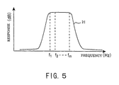
- a plurality of resonators are cascaded. Accordingly, by adequately setting the coupling factor between resonators "M2, M3,” representing a coupling factor of each resonator and external Q (coupling factor between resonators "M1, M4") representing a value to excite the resonator by input/output unit, designable frequency band and attenuation of stop-band for the filter circuit are determined.
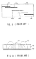
- Three microstrip conductors 163a, 163b, 163c having length equal to the half-wave length of the designable frequency band are formed between excitation lines 161, 162 of the input/output side by shifting every 1/4 wave length.
- the component element of the resonator is the microstrip conductor 163a and a circumferential dielectric (the dielectric substrate 164 and an exposure part (air)).
- the space between the resonators determines the value of the coupling factor between the resonators.
- the excitation lines 161, 162 of input/output side are located at a distance representing a desirable external Q from the resonator.
- the microstrip line filter circuit in which a superconducting conductor is used as the microstrip conductor is utilized.
- lines of electric force are generated in this microstrip line.
- the lines of electric force 174 generates in the dielectric 173 between the microstrip conductor 171 and the ground metal 172, and an electric field concentrates on a sectional edge of the line (the microstrip conductor 171) through which signal electric power passes.
- electric current concentrates on this edge part. Accordingly, in case of passing a large electric power, the electric current flowing through the edge exceeds the threshold of critical current density in spite of several-watt electric power, and it breaks the superconducting characteristic.
- the filter circuit using the microstrip line resonator in case of passing the large electric power, the electric current concentrates on the edge of the microstrip conductor. Accordingly, in case of using the superconducting conductor, the electric current exceeds the critical current density and breaks the superconducting characteristic.
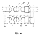
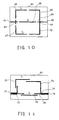
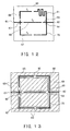
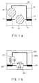
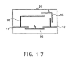
- a filter circuit comprising: a first resonator and a second resonator each having a different resonance frequency, a first block including the first resonator and a second block including the second resonator, wherein the first block includes a first delay unit connected to the first resonator; an input terminal configured to divide an input signal to the first block and the second block; and an output terminal configured to combine signals passing through the first block and the second block, and to output the combined signal; wherein said first delay unit converts a phase difference between the signals passing through the first block and the second block to reverse-phase or nearly reverse-phase.
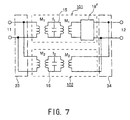
- a superconducting filter circuit comprising: a first resonator and a second resonator each having a variable resonance frequency, a first block including the first resonator and a second block including the second resonator, wherein the first block includes a delay unit connected to the first resonator; an input terminal configured to divide an input signal to the first block and the second block; and an output terminal configured to combine signals passing through the first block and the second block, and to output the combined signal; wherein the resonance frequency of at least one of the first resonator and the second resonator is varied by control signal from external.
- Fig. 15 shows an example of the filter circuit shown in Fig. 11 composed by a lumped element circuit.
- the resonator 205 (resonance frequency f1) and the resonator 206 (resonance frequency f2) each consist of a capacitor and an inductor
- the delay unit 203 consists of Au wiring.
- a block including the resonator 205 and the delay unit 203 cascaded and the resonator 206 are connected in parallel between the input terminal 201 and the output terminal 202.
Landscapes
- Control Of Motors That Do Not Use Commutators (AREA)
- Filters And Equalizers (AREA)
Applications Claiming Priority (4)
| Application Number | Priority Date | Filing Date | Title |
|---|---|---|---|
| JP2000095531 | 2000-03-30 | ||
| JP2000095531 | 2000-03-30 | ||
| JP2001019479 | 2001-01-29 | ||
| JP2001019479A JP2001345601A (ja) | 2000-03-30 | 2001-01-29 | フィルタ回路 |
Publications (2)
| Publication Number | Publication Date |
|---|---|
| EP1148576A2 true EP1148576A2 (fr) | 2001-10-24 |
| EP1148576A3 EP1148576A3 (fr) | 2003-01-29 |
Family
ID=26588980
Family Applications (1)
| Application Number | Title | Priority Date | Filing Date |
|---|---|---|---|
| EP01302499A Withdrawn EP1148576A3 (fr) | 2000-03-30 | 2001-03-19 | Circuit de filtre et circuit de filtre supraconducteur |
Country Status (3)
| Country | Link |
|---|---|
| US (2) | US6518854B2 (fr) |
| EP (1) | EP1148576A3 (fr) |
| JP (1) | JP2001345601A (fr) |
Cited By (2)
| Publication number | Priority date | Publication date | Assignee | Title |
|---|---|---|---|---|
| EP1394893A1 (fr) * | 2002-08-30 | 2004-03-03 | Murata Manufacturing Co., Ltd. | Filtre passe-bande à plusiers étages parallèles |
| US7317365B2 (en) | 2002-02-28 | 2008-01-08 | Marconi Communications Gmbh | Bandpass filter having parallel signal paths |
Families Citing this family (20)
| Publication number | Priority date | Publication date | Assignee | Title |
|---|---|---|---|---|
| US6748022B1 (en) * | 1999-07-06 | 2004-06-08 | Harold R. Walker | Single sideband suppressed carrier digital communications method and system |
| JP2004112668A (ja) * | 2002-09-20 | 2004-04-08 | Toshiba Corp | 共振器及びフィルタ |
| JP3981104B2 (ja) | 2004-06-28 | 2007-09-26 | 株式会社東芝 | フィルタ回路及びこれを用いた無線通信装置 |
| JP4314219B2 (ja) | 2005-07-04 | 2009-08-12 | 株式会社東芝 | フィルタ回路及びこれを用いた無線通信装置 |
| CN100392910C (zh) * | 2005-11-25 | 2008-06-04 | 中国科学院物理研究所 | 一种铁电薄膜可调带通滤波器 |
| JP2007174438A (ja) | 2005-12-23 | 2007-07-05 | Toshiba Corp | フィルタ回路及びフィルタを備えた無線通信システム |
| WO2007100760A2 (fr) * | 2006-02-27 | 2007-09-07 | The Penn State Research Foundation | Détection de signaux de résonance quadrupolaire au moyen de résonateurs surpaconducteurs à très haute température |
| JP4772574B2 (ja) | 2006-04-14 | 2011-09-14 | 株式会社東芝 | 増幅器および無線通信回路 |
| JP4303272B2 (ja) | 2006-09-15 | 2009-07-29 | 株式会社東芝 | フィルタ回路 |
| JP4264101B2 (ja) | 2006-12-08 | 2009-05-13 | 株式会社東芝 | フィルタ回路および無線通信装置 |
| JP4445533B2 (ja) * | 2007-08-28 | 2010-04-07 | 株式会社東芝 | フィルタ回路、無線通信装置および信号処理方法 |
| JP4996406B2 (ja) * | 2007-09-25 | 2012-08-08 | 株式会社東芝 | 増幅器、無線送信装置および無線受信装置 |
| JP4679618B2 (ja) | 2008-09-11 | 2011-04-27 | 株式会社東芝 | フィルタ回路および無線通信装置 |
| TWI422151B (zh) * | 2011-03-01 | 2014-01-01 | Univ Kun Shan | 四頻帶通濾波器 |
| KR20130038023A (ko) * | 2011-10-07 | 2013-04-17 | 한국전자통신연구원 | 고리형 공진기 및 필터 |
| US9236895B1 (en) * | 2014-05-09 | 2016-01-12 | Clearwire Ip Holdings Llc | Phase filter for radio frequency (RF) signals |
| JP6490928B2 (ja) * | 2014-09-08 | 2019-03-27 | 株式会社東芝 | マルチバンドフィルタ |
| CN109906551A (zh) * | 2016-11-08 | 2019-06-18 | 三菱电机株式会社 | 多波段滤波器 |
| US11211676B2 (en) | 2019-10-09 | 2021-12-28 | Com Dev Ltd. | Multi-resonator filters |
| CN114639932B (zh) * | 2022-03-25 | 2022-10-14 | 电子科技大学 | 一种微带差分带通滤波器 |
Family Cites Families (6)
| Publication number | Priority date | Publication date | Assignee | Title |
|---|---|---|---|---|
| US2716733A (en) * | 1950-05-10 | 1955-08-30 | Exxon Research Engineering Co | Variable bandwidth band-pass filter |
| FR1354860A (fr) * | 1962-12-19 | 1964-03-13 | Thomson Houston Comp Francaise | Filtre de bande à déphasage linéaire |
| JPH0812961B2 (ja) * | 1989-05-02 | 1996-02-07 | 株式会社村田製作所 | 並列多段型帯域通過フィルタ |
| US5184096A (en) * | 1989-05-02 | 1993-02-02 | Murata Manufacturing Co., Ltd. | Parallel connection multi-stage band-pass filter comprising resonators with impedance matching means capacitively coupled to input and output terminals |
| WO1995028746A2 (fr) * | 1994-04-14 | 1995-10-26 | E.I. Du Pont De Nemours And Company | Filtres a supraconducteurs haute temperature capables de traiter des courants eleves |
| DE19620932C1 (de) * | 1996-05-24 | 1997-08-21 | Bosch Gmbh Robert | Planarer Filter mit ferroelektrischen und/oder antiferroelektrischen Elementen |
-
2001
- 2001-01-29 JP JP2001019479A patent/JP2001345601A/ja active Pending
- 2001-03-19 EP EP01302499A patent/EP1148576A3/fr not_active Withdrawn
- 2001-03-19 US US09/810,479 patent/US6518854B2/en not_active Expired - Fee Related
-
2002
- 2002-08-02 US US10/210,084 patent/US6759930B2/en not_active Expired - Fee Related
Cited By (3)
| Publication number | Priority date | Publication date | Assignee | Title |
|---|---|---|---|---|
| US7317365B2 (en) | 2002-02-28 | 2008-01-08 | Marconi Communications Gmbh | Bandpass filter having parallel signal paths |
| EP1394893A1 (fr) * | 2002-08-30 | 2004-03-03 | Murata Manufacturing Co., Ltd. | Filtre passe-bande à plusiers étages parallèles |
| US6914497B2 (en) | 2002-08-30 | 2005-07-05 | Murata Manufacturing Co., Ltd. | Parallel multistage band-pass filter |
Also Published As
| Publication number | Publication date |
|---|---|
| US20010029241A1 (en) | 2001-10-11 |
| US6759930B2 (en) | 2004-07-06 |
| US20020186092A1 (en) | 2002-12-12 |
| US6518854B2 (en) | 2003-02-11 |
| EP1148576A3 (fr) | 2003-01-29 |
| JP2001345601A (ja) | 2001-12-14 |
Similar Documents
| Publication | Publication Date | Title |
|---|---|---|
| US6518854B2 (en) | Filter circuit and a superconducting filter circuit | |
| US7825751B2 (en) | Resonant circuit, filter circuit, and antenna device | |
| US5750473A (en) | Planar high temperature superconductor filters with backside coupling | |
| US6122533A (en) | Superconductive planar radio frequency filter having resonators with folded legs | |
| US6751489B2 (en) | High temperature superconductor mini-filters and mini-multiplexers with self-resonant spiral resonators | |
| US5616538A (en) | High temperature superconductor staggered resonator array bandpass filter | |
| US6026311A (en) | High temperature superconducting structures and methods for high Q, reduced intermodulation resonators and filters | |
| EP0780034B1 (fr) | Filtres a constante localisee | |
| CA2166014C (fr) | Circuits supraconducteurs haute puissance et procede de fabrication | |
| WO1995016288A1 (fr) | Symetriseur hyperfrequence peu encombrant a faibles pertes | |
| WO1998000880A9 (fr) | Filtre planaire de radiofrequences | |
| US20030001692A1 (en) | Voltage tunable varactors and tunable devices including such varactors | |
| EP1265310B1 (fr) | Filtre a microrubans supraconducteurs | |
| US5922650A (en) | Method and structure for high power HTS transmission lines using strips separated by a gap | |
| US5278529A (en) | Broadband microstrip filter apparatus having inteleaved resonator sections | |
| WO1995028746A2 (fr) | Filtres a supraconducteurs haute temperature capables de traiter des courants eleves | |
| US7071797B2 (en) | Method and apparatus for minimizing intermodulation with an asymmetric resonator | |
| GB2129624A (en) | A coupling circuit | |
| JP4679618B2 (ja) | フィルタ回路および無線通信装置 | |
| KR20100135272A (ko) | 초소형 모놀리식 전자기 공진기 | |
| KR100313893B1 (ko) | 협대역 초전도 대역 통과 필터 | |
| WO1997050144A1 (fr) | Filtres ou multiplexeurs supraconducteurs, plans et a haute temperature ayant leur branchement sur le cote arriere | |
| JP2000502231A (ja) | 信号をフィルタリングする装置およびそれに関連する方法 | |
| JP2005229304A (ja) | 高周波回路 | |
| JP2002076706A (ja) | フィルタ回路 |
Legal Events
| Date | Code | Title | Description |
|---|---|---|---|
| PUAI | Public reference made under article 153(3) epc to a published international application that has entered the european phase |
Free format text: ORIGINAL CODE: 0009012 |
|
| 17P | Request for examination filed |
Effective date: 20010330 |
|
| AK | Designated contracting states |
Kind code of ref document: A2 Designated state(s): AT BE CH CY DE DK ES FI FR GB GR IE IT LI LU MC NL PT SE TR |
|
| AX | Request for extension of the european patent |
Free format text: AL;LT;LV;MK;RO;SI |
|
| PUAL | Search report despatched |
Free format text: ORIGINAL CODE: 0009013 |
|
| AK | Designated contracting states |
Designated state(s): AT BE CH CY DE DK ES FI FR GB GR IE IT LI LU MC NL PT SE TR |
|
| AX | Request for extension of the european patent |
Extension state: AL LT LV MK RO SI |
|
| RIC1 | Information provided on ipc code assigned before grant |
Ipc: 7H 01P 1/203 B Ipc: 7H 01P 1/213 A |
|
| AKX | Designation fees paid |
Designated state(s): DE FR GB |
|
| 17Q | First examination report despatched |
Effective date: 20071228 |
|
| STAA | Information on the status of an ep patent application or granted ep patent |
Free format text: STATUS: THE APPLICATION IS DEEMED TO BE WITHDRAWN |
|
| 18D | Application deemed to be withdrawn |
Effective date: 20080508 |