EP1149023B1 - Fut a bondes - Google Patents
Fut a bondes Download PDFInfo
- Publication number
- EP1149023B1 EP1149023B1 EP00903525A EP00903525A EP1149023B1 EP 1149023 B1 EP1149023 B1 EP 1149023B1 EP 00903525 A EP00903525 A EP 00903525A EP 00903525 A EP00903525 A EP 00903525A EP 1149023 B1 EP1149023 B1 EP 1149023B1
- Authority
- EP
- European Patent Office
- Prior art keywords
- barrel
- housing
- edge
- lateral walls
- transitions
- Prior art date
- Legal status (The legal status is an assumption and is not a legal conclusion. Google has not performed a legal analysis and makes no representation as to the accuracy of the status listed.)
- Expired - Lifetime
Links
- 229920001169 thermoplastic Polymers 0.000 claims description 3
- 230000002093 peripheral effect Effects 0.000 claims 1
- 230000007704 transition Effects 0.000 abstract description 29
- 239000012815 thermoplastic material Substances 0.000 abstract 1
- 238000004519 manufacturing process Methods 0.000 description 4
- 239000000463 material Substances 0.000 description 3
- 239000004033 plastic Substances 0.000 description 3
- 229920003023 plastic Polymers 0.000 description 3
- 238000007664 blowing Methods 0.000 description 2
- 230000007423 decrease Effects 0.000 description 2
- 230000000694 effects Effects 0.000 description 2
- 238000000034 method Methods 0.000 description 2
- 239000011324 bead Substances 0.000 description 1
- 238000000071 blow moulding Methods 0.000 description 1
- 230000009969 flowable effect Effects 0.000 description 1
- 239000007788 liquid Substances 0.000 description 1
- 238000000465 moulding Methods 0.000 description 1
- 238000007493 shaping process Methods 0.000 description 1
- 230000035939 shock Effects 0.000 description 1
- 239000002689 soil Substances 0.000 description 1
- 239000004416 thermosoftening plastic Substances 0.000 description 1
Images



Classifications
-
- B—PERFORMING OPERATIONS; TRANSPORTING
- B65—CONVEYING; PACKING; STORING; HANDLING THIN OR FILAMENTARY MATERIAL
- B65D—CONTAINERS FOR STORAGE OR TRANSPORT OF ARTICLES OR MATERIALS, e.g. BAGS, BARRELS, BOTTLES, BOXES, CANS, CARTONS, CRATES, DRUMS, JARS, TANKS, HOPPERS, FORWARDING CONTAINERS; ACCESSORIES, CLOSURES, OR FITTINGS THEREFOR; PACKAGING ELEMENTS; PACKAGES
- B65D1/00—Rigid or semi-rigid containers having bodies formed in one piece, e.g. by casting metallic material, by moulding plastics, by blowing vitreous material, by throwing ceramic material, by moulding pulped fibrous material or by deep-drawing operations performed on sheet material
- B65D1/12—Cans, casks, barrels, or drums
- B65D1/20—Cans, casks, barrels, or drums characterised by location or arrangement of filling or discharge apertures
Definitions
- the invention relates to a bung from thermoplastic Plastic according to the preamble of claim 1.
- the invention has for its object a bung from to manufacture thermoplastic so that the residual emptying has even better properties than that Barrel according to EP 0 291 695 A2 and thereby easy to manufacture is.
- the invention can be summarized in that the two transitions each side wall of the case delimit above and below from the front boundary wall the same in the direction of the edge region of the barrel diverge with the result that the slope of each side wall decreases from the front wall towards the edge area.
- a bung is known from EP 0 515 390 B1, in which the top floor in addition to or next to the bunghole housing an essentially circular segment-shaped surface part or has a bevel, the bevel its lowest point on the side of the barrel jacket in the close range of the bunghole.
- this configuration has Consequence that a relatively large number in the area of the top floor curved and angled wall areas are available to the Part run approximately at right angles to each other and a stiffening of the topsoil, which when the Upper floor through shock and impact to uncontrollable tensions and impermissible stresses on the plastic material can lead.
- the application of the invention leads to a simpler design because the top floor next to the bunghole housing no further bevels and circular sections Areas needed to achieve the desired effect.
- Another advantage of the barrel according to the invention is in that since the side walls of the housing are flatter than in the prior art, the shape of the barrel in Blowing process is easier. This is particularly why Meaning because normally the interface of the in general two-part blow mold through the nozzle and thus through the nozzle housing runs with the result that the preform, from which the barrel by applying internal pressure is made between the two moldings straight is clamped near the area along the parting surface, in which the preform to form strongly angled and curved wall areas such. B. in the area of the housing must be deformed.
- transitions between the side walls of the housing and its Soil can run essentially parallel to each other. But it can also be useful to make these transitions from the front boundary wall of the housing in the direction to let something converge on the rim of the barrel, with the result that the bottom of the case towards the barrel edge somewhat becomes narrower and thus the two transitions even closer lie on the bung hole, which means that the residual emptying additionally is improved.
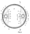
- Stackable bung barrel 10 has a barrel body 12, a Upper floor 14 and a lower floor 16.
- the top shelf 14 is provided with two trough-shaped depressions, each one Form housing 18 or 20 for a nozzle 22 or 24.
- everyone Neck limits an opening 25 and 26.
- the barrel 10 is in the Area of the top floor 14 with a circumferential transport ring 28 provided, which is supported by a circumferential web 58. The latter delimits an open top with the top floor 14 Slot 30.
- the barrel usually only one of the two openings of the barrel serves the remaining drain while the other opening for normal Emptying the barrel using, for example a pump enclosed pipe is used, which is inserted through the opening into the interior of the barrel. That the This housing can also be assigned to this opening be carried out in the usual way, that is to say as close as possible to get large stacking area.
- the barrel according to the Drawing is provided with two openings for residual emptying and shows possible different configurations of the Housing.
- both housings 18, 20 The depth of both housings 18, 20 is such that the respective Spigot 22 or 24 not up over the top Boundary surface 29 of the top floor, which is also a stacking surface serves, protrudes.
- Each of the two arranged in the edge region of the top floor 14 Housing 18, 20 is at its barrel edge or ring 28 facing side open.
- the ring 28 each facing side of the nozzle 22 or 24 is that Housing bounded by an end wall 32 and 34, respectively, which is inclined between the bottom 36 or 38 of the housing and the top floor 14 runs.
- transitions 44 between the housing base 36 and 38 and of the respective wall 40 or 42 and between the respective Wall and the top floor 14 provided, the latter Transitions are designated by 46.
- transitions delimiting the end walls 32 and 34 respectively 48, 50 which are substantially parallel the transitions 44 and 46 are arranged in a divergent manner such that starting from the respectively associated end wall 32 or 34 of the Distance between the transitions 44, 46 towards the L-ring and thus the barrel edge increases.
- each Housing 18, 20 and the housing base 36 and 38 extend close to the nozzle 22 or 24, so that when the upper transitions 46 an angle ⁇ of, for example, 140 ° include, each side wall 40, 42 an extension of about 70 ° in radians between the lower transition 44 and the upper transition 46 has.
- the respective radians therefore correspond to Length of the transition 70 between the side wall 40 and 42 on the one hand and the limitation of the groove 30 on the other. Since the Length of the transition 70 also in relation to the emptying in a certain position of the barrel determines the slope, the latter can therefore also about the choice of the size of the Angle ⁇ can be determined.
- An angle ⁇ of more than 180 ° is not normally considered if the keg is stackable should be, since then the stacking area will be reduced too much and there would be a risk that the nozzle would be a load-bearing one Function would have to take over.
- the housing 20 shown on the right in FIG. 2 runs the two transitions 44 from the end wall 34 starting essentially parallel to the barrel edge, on which the housing limited only on three sides by the walls is open. The latter also applies to the one shown on the left in FIG. 2 Housing 18, the lower transitions 44 of the side walls however, starting from the associated end wall 32, converge somewhat towards the edge of the barrel, causing the flowable filling material through the oblique side walls 42, 44 is brought closer to the outlet opening 26.
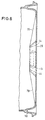
- Fig. 3 reveals that the bottom 36 of the housing 18 in the area between nozzle 22 and the barrel edge with a fold 52 is provided which one up from the housing bottom 36 protruding bead 54 forms a recess 56 on the inside of the housing base 36 corresponds.
- This fold forms a deformation zone between the barrel edge or the annular web 58 carrying the transport ring 28 on the one hand and the respective nozzle 22 and 24 on the other hand, the serves to act on the barrel edge towards the nozzle Intercept forces at least to the extent that no inadmissible Strains occur in the area of the nozzle. This effect is caused by a temporary deformation of the Crease reached. However, this is irrelevant since the fold after the impact or impact stress is back in the original situation springs back.
- the barrel 10 is on the inside with a essentially radial groove-shaped depression 60 (Fig. 3 and 5) provided, which is different from the fold 52 caused depression 56 approximately radially through the in the normal position of the barrel lower area of the nozzle 22 or 24 in the opening 25 and 26 bounded by this extends.
- a essentially radial groove-shaped depression 60 (Fig. 3 and 5) provided, which is different from the fold 52 caused depression 56 approximately radially through the in the normal position of the barrel lower area of the nozzle 22 or 24 in the opening 25 and 26 bounded by this extends.
- Edge area provided with a recess 62.
- the gutter 60 should enable the barrel to be emptied even further, thus also in the area between the nozzle and the barrel edge Product residues, if necessary by swiveling accordingly of the barrel from which the barrel can flow.
- Fig. 3 of the drawing it is shown that during the emptying of the rest of the filling, the latter approximately from area A over the lateral, preferably flat, boundary walls 40, 42 in the direction of arrows 64 in area B between the nozzles and barrel edge flows and from there in particular through the channel-shaped Well 60 in the nozzle and through this from the Barrel runs out.
Landscapes
- Engineering & Computer Science (AREA)
- Ceramic Engineering (AREA)
- Mechanical Engineering (AREA)
- Containers Having Bodies Formed In One Piece (AREA)
- Containers And Packaging Bodies Having A Special Means To Remove Contents (AREA)
- Rigid Containers With Two Or More Constituent Elements (AREA)
- Injection Moulding Of Plastics Or The Like (AREA)
- Surgical Instruments (AREA)
- Prostheses (AREA)
- Details Of Rigid Or Semi-Rigid Containers (AREA)
- General Details Of Gearings (AREA)
- Glass Compositions (AREA)
- Cyclones (AREA)
- Closures For Containers (AREA)
- Valve-Gear Or Valve Arrangements (AREA)
- Ultra Sonic Daignosis Equipment (AREA)
- Basic Packing Technique (AREA)
- Cartons (AREA)
- Connector Housings Or Holding Contact Members (AREA)
Claims (7)
- Fût à bonde en matière thermoplastique, comprenant un anneau de préhension et de transport (28) périphérique, agencé dans la zone du fond supérieur (14) et au moins une tubulure du trou de bonde (22, 24), qui est disposée dans la zone de bordure du fond supérieur à l'intérieur d'un réceptacle (18, 20), qui est encastré dans le fond supérieur et qui est ouvert sur son côté orienté vers le bord et dont le côté opposé au côté ouvert comporte une cloison frontale (32, 34), à partir des deux extrémités de laquelle s'étend respectivement une paroi (40, 42) délimitant latéralement le réceptacle en direction du bord du fût, sachant que les parois délimitant le réceptacle sont délimitées sur le côté supérieur par une jonction (46, 50) allant de la paroi concernée vers le fond supérieur et sur le côté inférieur par une jonction (48, 44) allant de la paroi concernée vers le fond du réceptacle (36, 38), et la distance entre les jonctions supérieures (46) des deux parois latérales du réceptacle est supérieure à la distance entre les deux jonctions inférieures (44), et les jonctions supérieures divergent en direction du bord du fût, caractérisé en ce que les jonctions (46) entre les parois latérales (40, 42) et le fond supérieur (14), d'une part, et les jonctions (44) entre les parois latérales (40, 42) et le fond du réceptacle (36, 38), d'autre part, ne sont pas parallèles entre elles, et les jonctions (46) entre les parois latérales (40, 42) et le fond supérieur (14) forment un angle (α), qui est au moins égal à 120°.
- Fût à bonde selon la revendication 1, caractérisé en ce que les jonctions (44) entre les parois latérales (40, 42) et le fond du réceptacle (38) sont sensiblement parallèles entre elles.
- Fût à bonde selon la revendication 1, caractérisé en ce que les jonctions (44) entre les parois latérales (40, 42) et le fond du réceptacle (36) convergent à partir de la cloison frontale (32) en direction du bord du fût.
- Fût à bonde selon la revendication 1, caractérisé en ce que les jonctions entre les parois latérales et le fond du réceptacle divergent à partir de la cloison frontale en direction du bord du fût, la dimension de la divergence étant inférieure à celle des jonctions entre les parois latérales et le fond supérieur.
- Fût à bonde selon la revendication 1, caractérisé en ce que l'angle (α) formé par les deux jonctions (46) entre les parois latérales (40, 42) et le fond supérieur n'est pas inférieur à 140°, de préférence il est égal à environ 160°.
- Fût à bonde selon la revendication 1, caractérisé en ce qu'il est prévu entre la partie à tubulure (22, 24) et le bord du fût une zone de déformation qui comporte au moins un pli (52) qui est sensiblement parallèle ou tangent au bord du fût.
- Fût à bonde selon la revendication 1, caractérisé en ce qu'un creux (60) en forme de gorge est réalisé sur le côté intérieur du fût entre la tubulure du trou de bonde (22, 24) et le pli (52).
Applications Claiming Priority (3)
| Application Number | Priority Date | Filing Date | Title |
|---|---|---|---|
| DE19905898 | 1999-02-10 | ||
| DE19905898A DE19905898A1 (de) | 1999-02-11 | 1999-02-11 | Spundfaß |
| PCT/DE2000/000096 WO2000047478A1 (fr) | 1999-02-11 | 2000-01-13 | Fut a bondes |
Publications (3)
| Publication Number | Publication Date |
|---|---|
| EP1149023A1 EP1149023A1 (fr) | 2001-10-31 |
| EP1149023B1 true EP1149023B1 (fr) | 2002-10-23 |
| EP1149023B2 EP1149023B2 (fr) | 2009-09-02 |
Family
ID=7897308
Family Applications (1)
| Application Number | Title | Priority Date | Filing Date |
|---|---|---|---|
| EP00903525A Expired - Lifetime EP1149023B2 (fr) | 1999-02-11 | 2000-01-13 | Fut a bondes |
Country Status (14)
| Country | Link |
|---|---|
| US (1) | US6145694A (fr) |
| EP (1) | EP1149023B2 (fr) |
| JP (1) | JP4692864B2 (fr) |
| KR (1) | KR100563793B1 (fr) |
| CN (1) | CN1230357C (fr) |
| AT (1) | ATE226542T1 (fr) |
| AU (1) | AU2534300A (fr) |
| BR (1) | BR0008166A (fr) |
| CA (1) | CA2360328A1 (fr) |
| DE (2) | DE19905898A1 (fr) |
| ID (1) | ID30047A (fr) |
| MX (1) | MXPA01008147A (fr) |
| TR (1) | TR200102291T2 (fr) |
| WO (1) | WO2000047478A1 (fr) |
Families Citing this family (3)
| Publication number | Priority date | Publication date | Assignee | Title |
|---|---|---|---|---|
| US6419109B1 (en) * | 2001-03-08 | 2002-07-16 | Russell-Stanley Corporation | Tighthead drum |
| DE102004061677B4 (de) | 2004-12-22 | 2007-05-10 | Schütz GmbH & Co. KGaA | Spundfaß |
| DE102005028705A1 (de) * | 2005-06-20 | 2006-12-28 | Heco Maschinen- Und Werkzeugbau Gmbh | Deckelteil für ein Spundfaß mit optimierter Restentleerung |
Family Cites Families (14)
| Publication number | Priority date | Publication date | Assignee | Title |
|---|---|---|---|---|
| DE3024810A1 (de) * | 1980-07-01 | 1982-01-28 | Mauser-Werke GmbH, 5040 Brühl | Spundfass |
| DE3636758A1 (de) * | 1986-10-29 | 1988-05-05 | Mauser Werke Gmbh | Spundfass |
| DE8631318U1 (de) * | 1986-11-22 | 1987-01-15 | Schütz-Werke GmbH & Co KG, 5418 Selters | Spundfaß |
| DE8705915U1 (de) * | 1987-04-23 | 1987-06-25 | Kautex Werke Reinold Hagen AG, 5300 Bonn | Faß aus thermoplastischem Kunststoff |
| DE8705916U1 (de) † | 1987-04-23 | 1987-06-25 | Kautex Werke Reinold Hagen AG, 5300 Bonn | Faß aus thermoplastischem Kunststoff |
| US4941584A (en) * | 1987-12-03 | 1990-07-17 | Ashland Oil Inc. | Reusable plastic drum container assembly |
| ES2046432T3 (es) * | 1988-10-28 | 1994-02-01 | Sotralentz S.A. | Procedimiento para la babricacion de un barril con tapon con la envolvente del barril, fondo del barril y tapa del barril. |
| DE8908528U1 (de) * | 1989-07-13 | 1989-08-31 | Schütz-Werke GmbH & Co KG, 5418 Selters | Spundfaß |
| DE4016600A1 (de) * | 1990-02-15 | 1991-08-22 | Mauser Werke Gmbh | Spundfass |
| DE4016785A1 (de) * | 1990-05-25 | 1991-11-28 | Kautex Maschinenbau Gmbh | Fass aus thermoplastischem kunststoff |
| US5217142A (en) * | 1991-03-16 | 1993-06-08 | Schuetz Udo | Stackable bunghole barrel of synthetic resin |
| DE4206405C2 (de) † | 1991-03-16 | 1995-09-21 | Schuetz Werke Gmbh Co Kg | Stapelbares Spundfaß aus Kunststoff |
| DE4236338C2 (de) * | 1992-10-28 | 1999-12-30 | Mauser Werke Gmbh | Faßdeckel |
| US5273181A (en) * | 1993-01-26 | 1993-12-28 | Greif Bros. Corporation | Plastic drum with drain sump and method of making the same |
-
1999
- 1999-02-11 DE DE19905898A patent/DE19905898A1/de not_active Withdrawn
-
2000
- 2000-01-13 BR BR0008166-3A patent/BR0008166A/pt not_active IP Right Cessation
- 2000-01-13 TR TR2001/02291T patent/TR200102291T2/xx unknown
- 2000-01-13 ID IDW00200101721A patent/ID30047A/id unknown
- 2000-01-13 DE DE50000674T patent/DE50000674D1/de not_active Expired - Lifetime
- 2000-01-13 EP EP00903525A patent/EP1149023B2/fr not_active Expired - Lifetime
- 2000-01-13 CN CNB008036721A patent/CN1230357C/zh not_active Expired - Lifetime
- 2000-01-13 AT AT00903525T patent/ATE226542T1/de not_active IP Right Cessation
- 2000-01-13 US US09/482,427 patent/US6145694A/en not_active Expired - Fee Related
- 2000-01-13 MX MXPA01008147A patent/MXPA01008147A/es active IP Right Grant
- 2000-01-13 AU AU25343/00A patent/AU2534300A/en not_active Abandoned
- 2000-01-13 CA CA002360328A patent/CA2360328A1/fr not_active Abandoned
- 2000-01-13 KR KR1020017010153A patent/KR100563793B1/ko not_active Expired - Lifetime
- 2000-01-13 JP JP2000598406A patent/JP4692864B2/ja not_active Expired - Fee Related
- 2000-01-13 WO PCT/DE2000/000096 patent/WO2000047478A1/fr not_active Ceased
Also Published As
| Publication number | Publication date |
|---|---|
| WO2000047478A1 (fr) | 2000-08-17 |
| TR200102291T2 (tr) | 2001-12-21 |
| AU2534300A (en) | 2000-08-29 |
| CA2360328A1 (fr) | 2000-08-17 |
| KR100563793B1 (ko) | 2006-03-27 |
| ID30047A (id) | 2001-11-01 |
| EP1149023A1 (fr) | 2001-10-31 |
| ATE226542T1 (de) | 2002-11-15 |
| MXPA01008147A (es) | 2002-10-23 |
| KR20010103008A (ko) | 2001-11-17 |
| DE19905898A1 (de) | 2000-08-24 |
| BR0008166A (pt) | 2002-01-22 |
| EP1149023B2 (fr) | 2009-09-02 |
| CN1341068A (zh) | 2002-03-20 |
| JP4692864B2 (ja) | 2011-06-01 |
| DE50000674D1 (de) | 2002-11-28 |
| CN1230357C (zh) | 2005-12-07 |
| JP2002536258A (ja) | 2002-10-29 |
| US6145694A (en) | 2000-11-14 |
Similar Documents
| Publication | Publication Date | Title |
|---|---|---|
| AT395573B (de) | Behaelter aus kunststoff mit kreisfoermigem querschnitt | |
| DE69624069T2 (de) | Flasche mit einem Henkel und Verfahren zur Herstellung der Flasche durch Streckblasformen | |
| EP2163483B1 (fr) | Récipient en matière synthétique | |
| EP0147423B1 (fr) | Fermeture en plastique | |
| EP0786417B1 (fr) | Tube en plastique présentant un corps de tube et procédé pour sa fabrication | |
| CH658033A5 (de) | Behaelter. | |
| DE202008012290U1 (de) | Kunststoffbehältnis | |
| DE68916429T2 (de) | Blasgeformter flaschenförmiger Kunststoffbehälter. | |
| DE4202218C2 (de) | Mehrwegspulenkörper | |
| EP1149023B1 (fr) | Fut a bondes | |
| EP0291695A2 (fr) | Baril en matière thermoplastique | |
| EP0287966B1 (fr) | Baril en matière thermoplastique | |
| EP1853485B1 (fr) | Element verseur d'un emballage destine a recevoir des produits fluides et procede de production d'un tel emballage | |
| DE69329757T2 (de) | Verbesserter Ventilaufsatz für Druckbefüllung | |
| WO2002094671A1 (fr) | Fermeture a aeration integree | |
| DE29919867U1 (de) | Spundfaß | |
| DE4305138A1 (en) | Safety closure for bottles etc.with cap and safety ring with break line - has recesses between sectors formed around flanged lower edge of safety ring | |
| WO2016074809A1 (fr) | Récipient avec canal de ventilation | |
| WO1994001338A1 (fr) | Recipient | |
| EP3404307A1 (fr) | Raccord | |
| DE202016006324U1 (de) | Kunststoff-Verschlusskörper für einen Bügelverschluss von Flaschen, Bügelverschluss mit Kunststoff-Verschlusskörper und Spritzgussform zur Herstellung von Kunststoff-Verschlusskörpern | |
| DE10304452C5 (de) | Behältnis zur Aufnahme von Beschichtungsstoffen | |
| DE19515687C2 (de) | Verschluß für Gefäße, insbesondere Flaschen | |
| DE102006001454B4 (de) | Spritzgießwerkzeug | |
| DE102020210367A1 (de) | Wiederverschliessbare produktverpackung |
Legal Events
| Date | Code | Title | Description |
|---|---|---|---|
| PUAI | Public reference made under article 153(3) epc to a published international application that has entered the european phase |
Free format text: ORIGINAL CODE: 0009012 |
|
| 17P | Request for examination filed |
Effective date: 20010807 |
|
| AK | Designated contracting states |
Kind code of ref document: A1 Designated state(s): AT BE CH CY DE DK ES FI FR GB GR IE IT LI LU MC NL PT SE |
|
| GRAG | Despatch of communication of intention to grant |
Free format text: ORIGINAL CODE: EPIDOS AGRA |
|
| 17Q | First examination report despatched |
Effective date: 20020204 |
|
| GRAG | Despatch of communication of intention to grant |
Free format text: ORIGINAL CODE: EPIDOS AGRA |
|
| GRAH | Despatch of communication of intention to grant a patent |
Free format text: ORIGINAL CODE: EPIDOS IGRA |
|
| RAP1 | Party data changed (applicant data changed or rights of an application transferred) |
Owner name: SIG KAUTEX GMBH & CO.KG |
|
| GRAH | Despatch of communication of intention to grant a patent |
Free format text: ORIGINAL CODE: EPIDOS IGRA |
|
| GRAA | (expected) grant |
Free format text: ORIGINAL CODE: 0009210 |
|
| AK | Designated contracting states |
Kind code of ref document: B1 Designated state(s): AT BE CH CY DE DK ES FI FR GB GR IE IT LI LU MC NL PT SE |
|
| PG25 | Lapsed in a contracting state [announced via postgrant information from national office to epo] |
Ref country code: IE Free format text: LAPSE BECAUSE OF FAILURE TO SUBMIT A TRANSLATION OF THE DESCRIPTION OR TO PAY THE FEE WITHIN THE PRESCRIBED TIME-LIMIT Effective date: 20021023 Ref country code: FI Free format text: LAPSE BECAUSE OF FAILURE TO SUBMIT A TRANSLATION OF THE DESCRIPTION OR TO PAY THE FEE WITHIN THE PRESCRIBED TIME-LIMIT Effective date: 20021023 Ref country code: GR Free format text: LAPSE BECAUSE OF FAILURE TO SUBMIT A TRANSLATION OF THE DESCRIPTION OR TO PAY THE FEE WITHIN THE PRESCRIBED TIME-LIMIT Effective date: 20021023 |
|
| REF | Corresponds to: |
Ref document number: 226542 Country of ref document: AT Date of ref document: 20021115 Kind code of ref document: T |
|
| REG | Reference to a national code |
Ref country code: GB Ref legal event code: FG4D Free format text: NOT ENGLISH |
|
| REG | Reference to a national code |
Ref country code: CH Ref legal event code: EP |
|
| REG | Reference to a national code |
Ref country code: IE Ref legal event code: FG4D Free format text: GERMAN |
|
| REF | Corresponds to: |
Ref document number: 50000674 Country of ref document: DE Date of ref document: 20021128 |
|
| PG25 | Lapsed in a contracting state [announced via postgrant information from national office to epo] |
Ref country code: LU Free format text: LAPSE BECAUSE OF NON-PAYMENT OF DUE FEES Effective date: 20030113 Ref country code: AT Free format text: LAPSE BECAUSE OF NON-PAYMENT OF DUE FEES Effective date: 20030113 Ref country code: CY Free format text: LAPSE BECAUSE OF FAILURE TO SUBMIT A TRANSLATION OF THE DESCRIPTION OR TO PAY THE FEE WITHIN THE PRESCRIBED TIME-LIMIT Effective date: 20030113 |
|
| PG25 | Lapsed in a contracting state [announced via postgrant information from national office to epo] |
Ref country code: DK Free format text: LAPSE BECAUSE OF FAILURE TO SUBMIT A TRANSLATION OF THE DESCRIPTION OR TO PAY THE FEE WITHIN THE PRESCRIBED TIME-LIMIT Effective date: 20030123 Ref country code: PT Free format text: LAPSE BECAUSE OF FAILURE TO SUBMIT A TRANSLATION OF THE DESCRIPTION OR TO PAY THE FEE WITHIN THE PRESCRIBED TIME-LIMIT Effective date: 20030123 Ref country code: SE Free format text: LAPSE BECAUSE OF FAILURE TO SUBMIT A TRANSLATION OF THE DESCRIPTION OR TO PAY THE FEE WITHIN THE PRESCRIBED TIME-LIMIT Effective date: 20030123 |
|
| PG25 | Lapsed in a contracting state [announced via postgrant information from national office to epo] |
Ref country code: MC Free format text: LAPSE BECAUSE OF NON-PAYMENT OF DUE FEES Effective date: 20030131 |
|
| GBT | Gb: translation of ep patent filed (gb section 77(6)(a)/1977) |
Effective date: 20030220 |
|
| ET | Fr: translation filed | ||
| PG25 | Lapsed in a contracting state [announced via postgrant information from national office to epo] |
Ref country code: ES Free format text: LAPSE BECAUSE OF FAILURE TO SUBMIT A TRANSLATION OF THE DESCRIPTION OR TO PAY THE FEE WITHIN THE PRESCRIBED TIME-LIMIT Effective date: 20030429 |
|
| REG | Reference to a national code |
Ref country code: IE Ref legal event code: FD4D Ref document number: 1149023E Country of ref document: IE |
|
| PLBQ | Unpublished change to opponent data |
Free format text: ORIGINAL CODE: EPIDOS OPPO |
|
| PLBI | Opposition filed |
Free format text: ORIGINAL CODE: 0009260 |
|
| PLAX | Notice of opposition and request to file observation + time limit sent |
Free format text: ORIGINAL CODE: EPIDOSNOBS2 |
|
| 26 | Opposition filed |
Opponent name: MAUSER-WERKE GMBH Effective date: 20030723 |
|
| NLR1 | Nl: opposition has been filed with the epo |
Opponent name: MAUSER-WERKE GMBH |
|
| PLAX | Notice of opposition and request to file observation + time limit sent |
Free format text: ORIGINAL CODE: EPIDOSNOBS2 |
|
| PG25 | Lapsed in a contracting state [announced via postgrant information from national office to epo] |
Ref country code: CH Free format text: LAPSE BECAUSE OF NON-PAYMENT OF DUE FEES Effective date: 20040131 Ref country code: LI Free format text: LAPSE BECAUSE OF NON-PAYMENT OF DUE FEES Effective date: 20040131 |
|
| PLBB | Reply of patent proprietor to notice(s) of opposition received |
Free format text: ORIGINAL CODE: EPIDOSNOBS3 |
|
| REG | Reference to a national code |
Ref country code: CH Ref legal event code: PL |
|
| PLAY | Examination report in opposition despatched + time limit |
Free format text: ORIGINAL CODE: EPIDOSNORE2 |
|
| PLAY | Examination report in opposition despatched + time limit |
Free format text: ORIGINAL CODE: EPIDOSNORE2 |
|
| PLBC | Reply to examination report in opposition received |
Free format text: ORIGINAL CODE: EPIDOSNORE3 |
|
| APBP | Date of receipt of notice of appeal recorded |
Free format text: ORIGINAL CODE: EPIDOSNNOA2O |
|
| APAH | Appeal reference modified |
Free format text: ORIGINAL CODE: EPIDOSCREFNO |
|
| APBP | Date of receipt of notice of appeal recorded |
Free format text: ORIGINAL CODE: EPIDOSNNOA2O |
|
| PLAB | Opposition data, opponent's data or that of the opponent's representative modified |
Free format text: ORIGINAL CODE: 0009299OPPO |
|
| R26 | Opposition filed (corrected) |
Opponent name: MAUSER-WERKE GMBH & CO. KG Effective date: 20030723 |
|
| RAP2 | Party data changed (patent owner data changed or rights of a patent transferred) |
Owner name: KAUTEX MASCHINENBAU GMBH |
|
| APBQ | Date of receipt of statement of grounds of appeal recorded |
Free format text: ORIGINAL CODE: EPIDOSNNOA3O |
|
| NLR1 | Nl: opposition has been filed with the epo |
Opponent name: MAUSER-WERKE GMBH & CO. KG |
|
| NLT2 | Nl: modifications (of names), taken from the european patent patent bulletin |
Owner name: KAUTEX MASCHINENBAU GMBH Effective date: 20061122 |
|
| APBU | Appeal procedure closed |
Free format text: ORIGINAL CODE: EPIDOSNNOA9O |
|
| PUAH | Patent maintained in amended form |
Free format text: ORIGINAL CODE: 0009272 |
|
| STAA | Information on the status of an ep patent application or granted ep patent |
Free format text: STATUS: PATENT MAINTAINED AS AMENDED |
|
| 27A | Patent maintained in amended form |
Effective date: 20090902 |
|
| AK | Designated contracting states |
Kind code of ref document: B2 Designated state(s): AT BE CH CY DE DK ES FI FR GB GR IE IT LI LU MC NL PT SE |
|
| REG | Reference to a national code |
Ref country code: ES Ref legal event code: FD2A Effective date: 20030114 |
|
| NLR2 | Nl: decision of opposition |
Effective date: 20090902 |
|
| NLR3 | Nl: receipt of modified translations in the netherlands language after an opposition procedure | ||
| REG | Reference to a national code |
Ref country code: DE Ref legal event code: R082 Ref document number: 50000674 Country of ref document: DE Representative=s name: KIERDORF RITSCHEL PATENTANWAELTE PARTG MBB, DE Ref country code: DE Ref legal event code: R082 Ref document number: 50000674 Country of ref document: DE Representative=s name: KIERDORF RITSCHEL RICHLY PATENTANWAELTE PARTG , DE |
|
| REG | Reference to a national code |
Ref country code: DE Ref legal event code: R082 Ref document number: 50000674 Country of ref document: DE Representative=s name: KIERDORF RITSCHEL PATENTANWAELTE PARTG MBB, DE Ref country code: DE Ref legal event code: R082 Ref document number: 50000674 Country of ref document: DE Representative=s name: KIERDORF RITSCHEL RICHLY PATENTANWAELTE PARTG , DE |
|
| REG | Reference to a national code |
Ref country code: FR Ref legal event code: PLFP Year of fee payment: 16 |
|
| REG | Reference to a national code |
Ref country code: FR Ref legal event code: PLFP Year of fee payment: 17 |
|
| REG | Reference to a national code |
Ref country code: FR Ref legal event code: PLFP Year of fee payment: 18 |
|
| REG | Reference to a national code |
Ref country code: FR Ref legal event code: PLFP Year of fee payment: 19 |
|
| PGFP | Annual fee paid to national office [announced via postgrant information from national office to epo] |
Ref country code: NL Payment date: 20180124 Year of fee payment: 19 |
|
| PGFP | Annual fee paid to national office [announced via postgrant information from national office to epo] |
Ref country code: DE Payment date: 20180124 Year of fee payment: 19 Ref country code: GB Payment date: 20180125 Year of fee payment: 19 |
|
| PGFP | Annual fee paid to national office [announced via postgrant information from national office to epo] |
Ref country code: BE Payment date: 20180124 Year of fee payment: 19 Ref country code: IT Payment date: 20180126 Year of fee payment: 19 Ref country code: FR Payment date: 20180124 Year of fee payment: 19 |
|
| REG | Reference to a national code |
Ref country code: DE Ref legal event code: R119 Ref document number: 50000674 Country of ref document: DE |
|
| REG | Reference to a national code |
Ref country code: NL Ref legal event code: MM Effective date: 20190201 |
|
| GBPC | Gb: european patent ceased through non-payment of renewal fee |
Effective date: 20190113 |
|
| REG | Reference to a national code |
Ref country code: BE Ref legal event code: MM Effective date: 20190131 |
|
| PG25 | Lapsed in a contracting state [announced via postgrant information from national office to epo] |
Ref country code: FR Free format text: LAPSE BECAUSE OF NON-PAYMENT OF DUE FEES Effective date: 20190131 Ref country code: DE Free format text: LAPSE BECAUSE OF NON-PAYMENT OF DUE FEES Effective date: 20190801 Ref country code: NL Free format text: LAPSE BECAUSE OF NON-PAYMENT OF DUE FEES Effective date: 20190201 |
|
| PG25 | Lapsed in a contracting state [announced via postgrant information from national office to epo] |
Ref country code: BE Free format text: LAPSE BECAUSE OF NON-PAYMENT OF DUE FEES Effective date: 20190131 |
|
| PG25 | Lapsed in a contracting state [announced via postgrant information from national office to epo] |
Ref country code: GB Free format text: LAPSE BECAUSE OF NON-PAYMENT OF DUE FEES Effective date: 20190113 |
|
| PG25 | Lapsed in a contracting state [announced via postgrant information from national office to epo] |
Ref country code: IT Free format text: LAPSE BECAUSE OF NON-PAYMENT OF DUE FEES Effective date: 20190113 |