EP1149332B1 - Lichterfassungsvorrichtung - Google Patents
Lichterfassungsvorrichtung Download PDFInfo
- Publication number
- EP1149332B1 EP1149332B1 EP99958394A EP99958394A EP1149332B1 EP 1149332 B1 EP1149332 B1 EP 1149332B1 EP 99958394 A EP99958394 A EP 99958394A EP 99958394 A EP99958394 A EP 99958394A EP 1149332 B1 EP1149332 B1 EP 1149332B1
- Authority
- EP
- European Patent Office
- Prior art keywords
- light
- detection apparatus
- light detection
- cleaning device
- detecting
- Prior art date
- Legal status (The legal status is an assumption and is not a legal conclusion. Google has not performed a legal analysis and makes no representation as to the accuracy of the status listed.)
- Expired - Lifetime
Links
Images




Classifications
-
- G—PHYSICS
- G01—MEASURING; TESTING
- G01S—RADIO DIRECTION-FINDING; RADIO NAVIGATION; DETERMINING DISTANCE OR VELOCITY BY USE OF RADIO WAVES; LOCATING OR PRESENCE-DETECTING BY USE OF THE REFLECTION OR RERADIATION OF RADIO WAVES; ANALOGOUS ARRANGEMENTS USING OTHER WAVES
- G01S15/00—Systems using the reflection or reradiation of acoustic waves, e.g. sonar systems
- G01S15/88—Sonar systems specially adapted for specific applications
- G01S15/93—Sonar systems specially adapted for specific applications for anti-collision purposes
- G01S15/931—Sonar systems specially adapted for specific applications for anti-collision purposes of land vehicles
-
- G—PHYSICS
- G01—MEASURING; TESTING
- G01S—RADIO DIRECTION-FINDING; RADIO NAVIGATION; DETERMINING DISTANCE OR VELOCITY BY USE OF RADIO WAVES; LOCATING OR PRESENCE-DETECTING BY USE OF THE REFLECTION OR RERADIATION OF RADIO WAVES; ANALOGOUS ARRANGEMENTS USING OTHER WAVES
- G01S3/00—Direction-finders for determining the direction from which infrasonic, sonic, ultrasonic or electromagnetic waves, or particle emission, not having a directional significance, are being received
- G01S3/78—Direction-finders for determining the direction from which infrasonic, sonic, ultrasonic or electromagnetic waves, or particle emission, not having a directional significance, are being received using electromagnetic waves other than radio waves
- G01S3/781—Details
-
- G—PHYSICS
- G01—MEASURING; TESTING
- G01S—RADIO DIRECTION-FINDING; RADIO NAVIGATION; DETERMINING DISTANCE OR VELOCITY BY USE OF RADIO WAVES; LOCATING OR PRESENCE-DETECTING BY USE OF THE REFLECTION OR RERADIATION OF RADIO WAVES; ANALOGOUS ARRANGEMENTS USING OTHER WAVES
- G01S3/00—Direction-finders for determining the direction from which infrasonic, sonic, ultrasonic or electromagnetic waves, or particle emission, not having a directional significance, are being received
- G01S3/78—Direction-finders for determining the direction from which infrasonic, sonic, ultrasonic or electromagnetic waves, or particle emission, not having a directional significance, are being received using electromagnetic waves other than radio waves
- G01S3/782—Systems for determining direction or deviation from predetermined direction
-
- G—PHYSICS
- G01—MEASURING; TESTING
- G01S—RADIO DIRECTION-FINDING; RADIO NAVIGATION; DETERMINING DISTANCE OR VELOCITY BY USE OF RADIO WAVES; LOCATING OR PRESENCE-DETECTING BY USE OF THE REFLECTION OR RERADIATION OF RADIO WAVES; ANALOGOUS ARRANGEMENTS USING OTHER WAVES
- G01S5/00—Position-fixing by co-ordinating two or more direction or position line determinations; Position-fixing by co-ordinating two or more distance determinations
- G01S5/16—Position-fixing by co-ordinating two or more direction or position line determinations; Position-fixing by co-ordinating two or more distance determinations using electromagnetic waves other than radio waves
Definitions
- This invention relates to light detection apparatus for determining the location of a body within an area and to an autonomous vehicle, typically a robotic cleaning device, equipped with such light detection apparatus.
- the present invention seeks to provide an improved light detection apparatus which is suitable for use on an autonomous vehicle.
- a first aspect of the present invention provides light detection apparatus for determining the location of a body within an area, the apparatus comprising at least two light detecting devices for mounting on the body and capable of receiving light from the environment in which the body is located, the devices being located at respective detecting points which are angularly spaced about a vertical axis, means for supplying information representative of the levels of at least two different light types received at each detecting point, and means for comparing information received from the light detection apparatus with information previously received from the light detection apparatus and stored in a memory so as to identify when the light detected by the light detection apparatus is the same or substantially the same as light previously detected by the light detection apparatus.
- a further aspect of the invention provides an autonomous vehicle comprising power operated means for moving the vehicle around an area and a navigation system for identifying the location of the vehicle, the navigation system including the above described light detection apparatus for allowing the vehicle to determine when it has returned to a similar position in the area.
- the apparatus can better discriminate a set of light measurements taken at one position in an area from another position in the area.
- the light types can be ambient light and artificial light, such as incandescent light and fluorescent light.
- the information about different light types can be derived by filtering or by processing the signal received by each light detecting device to derive information about the level of constant (natural light) and time-varying (artificial) light types.
- the apparatus is particularly useful in an indoor environment where there is usually a mixture of natural and artificial light, the respective light sources being differently positioned within a room.
- the light detecting devices can be phototransistors or photodiodes. Alternatively, they can be a CCD array.
- the points at which light is received are spaced equi-angularly about the vertical axis. This gives the apparatus rotational symmetry.
- the light detection devices are all supported in a horizontal plane.
- the light detecting devices can be supported within a housing which can be mounted on an autonomous vehicle.
- the autonomous vehicle can be a robotic floor cleaning device, such as a robotic vacuum cleaner.
- the light detection apparatus is supported on an uppermost part of the body with the light detecting devices being supported so that they can receive light over an incident beam angle in a vertical plane extending upwardly from the horizon.
- an autonomous floor cleaning device for cleaning a floor area comprising:
- the use of the light detection apparatus can avoid the need for navigation beacons.
- the light detection apparatus is particularly useful where the cleaning device performs a spiralling pattern of coverage of the floor area. After each circuit of the floor area the cleaning device returns to a similar position in the area and this causes the cleaning device to step inwardly (if the spiral is an inward spiral) or outwardly (if the spiral is an outward spiral) by a step distance.
- the step distance can be fixed, such as one, or substantially one width of the cleaning device, or it can be selectable by a user.
- aspects of the invention provide a navigation system and software for operating a control processor in a navigation system, which cause an autonomous vehicle to operate in the above way. Further aspects of the invention provide a method of determining position of a body within an area using the light detection apparatus and a method of controlling operation of a cleaning device using information received from the light detection apparatus.
- the light detection apparatus shown therein comprises eight light detecting devices 10, typically phototransistors or photodiodes, equi-angularly spaced about a central axis 8 and mounted in a plastics housing 11.
- the plastics housing 11 can be mounted on a body of, for example, an autonomous vehicle or other device whose location is to be determined.
- the light detecting devices 10 are arranged in a common plane, typically an in use horizontal plane, for measuring the light received at eight different compass points around the light detection apparatus.
- the light detecting devices 10 face outwardly from the central axis 8.
- separating members 5 are positioned between adjacent ones of the light detecting devices 10.
- the separating members 5 serve to restrict the field-of-view of each device 10. It is also preferred to mount the detecting devices 10 radially inwardly from the periphery of housing 11, as shown in Figure 1A, as the separating members 5 then have a greater effect in shaping the field-of-view of the light detecting devices.
- FIG. 1B An alternative arrangement is shown in Figure 1B, in which three light detecting devices 10' are provided.
- the light detecting devices 10' are arranged in a non-equi-angular manner, but still about the vertical axis 8.
- the light detecting devices are able to receive light over an incident beam angle of around 120° so that the majority of the light approaching the housing 11 is detected by at least one detector 10'.
- the light detectors form a charge-coupled device (CCD) comprising a number (in this case six) of light receivers 10" which conduct the received light via optical conductors 10a to a central array of light detectors 10b where the light is detected.
- CCD charge-coupled device
- Figure 1D is an exploded view of the light detection apparatus.
- a printed circuit board 31 supports the array of light detecting devices 10.
- Leads 30 carry signals from the board 31.
- the detecting devices 10 are held in position between an insert 32 and an outer ring 33.
- Ribs 34 of the outer ring 33 fit between adjacent ones of the light detecting devices 10.
- the ribs 34 serve the function of separating members 5 in Figure 1A and help to define the angle of view of the detector, such that each detector provides a measurement indicative of light seen only by itself.
- a hemispherical transparent plastics part 35 fits over the outer ring and the devices and shields the devices. With this arrangement, the light detectors can receive light from a full 360° field-of view.
- the apparatus is compact and rugged and can easily be accommodated on an autonomous vehicle. It is particularly suitable for positioning on an upper face of an autonomous vehicle.
- Figure 1E is a side view of the detection apparatus.
- the light detecting device 10 is supported at an angle to the horizontal so that the field of view of the device extends, in the vertical plane, upwards from the horizon.
- the device 10 is held in this position by outer ring 33 and insert 32 (not shown).
- a more preferred arrangement is to provide one detector which is responsive to the full range of expected light types at each detection position.
- the signal output by each detector is then processed to derive signals indicative of each light type.
- One form of processing is to filter the output from each detector.
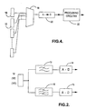
- the signal from each light detecting device 10, 10', 10" is fed into a filter network as shown in Figure 2.
- the filter network comprises a low pass filter 12, typically operating at around 10 Hz, and a band pass filter 13, typically operating at around 70 Hz.
- the low pass filter 12 passes a signal representative of ambient or natural light detected and the band pass filter 13 passes a signal representative of artificial light, i.e. incandescent and fluorescent light detected.
- band pass filters typically operating at around 50 Hz and 100 Hz, to pass signals representative of incandescent and fluorescent light, respectively, detected.
- the outputs of the filters 12 and 13 are fed into analogue-to-digital converters 14 and 15, and the digitised values are stored.
- FIG. 3 Another form of processing is to convert the signal into digital form and to monitor the digitised signal over a time interval to derive values indicative of the different light types.
- the signal returned by a light detector 10 is shown in Figure 3.
- the received signal has two components. There is a constant or d.c. quantity 47 caused by natural light, such as daylight, and a time-varying quantity caused by artificial light sources, such as incandescent lights and fluorescent lights. Incandescent lights vary in brightness according to the frequency of the mains electricity supply which passes through them. While, of course, natural light does have a frequency, the varying amplitude of the light will not be detected due to the light detecting device smoothing the received light into an average value. Monitoring over a 10ms period has been found to be effective.
- Figure 4 shows apparatus for performing this method.
- Outputs from each light detector 10 are fed to processing circuitry 22 on a time-multiplexed basis.
- a multiplexor 18 couples the output from light detector 10 to an analogue-to-digital converter 20 and the processing circuitry 22.
- the processing circuitry 22 looks for the minimum (45, Figure 3) and maximum (46, Figure 3) values of the received signal over the monitored time period. From the maximum and minimum values, the processing circuitry can derive the peak-to-peak range of the time-varying portion of the light, this being the difference between the maximum and minimum values.
- the d.c. value of the light is equivalent to the minimum value 45.
- the processing can be performed by digital logic circuitry in the form of a FPGA, an ASIC or by software running on a microprocessor.
- the multiplexor 18 operates to sequentially receive a signal from each of the light detectors 10.
- the light detection apparatus described above have eight, three and six light detecting devices 10, 10', 10" respectively. However, it is possible to provide as few as two light detecting devices (provided that they are substantially equi-angularly spaced about the axis 8) or more than eight light detecting devices. However, there should preferably be an even number of light detecting devices and it is preferable that they are equi-angularly spaced about a central vertical axis in order to provide the body or housing with rotational symmetry. It is appreciated that the desirability of rotational symmetry diminishes as the number of light detecting devices provided increases. Each light detecting device, preferably, receives light over an incident beam angle in an in use horizontal plane calculated approximately by dividing 360° by the number of detecting devices provided. Again, the desirability of this preferred feature diminishes as the number of light detecting devices increases.
- the light detecting devices 10, 10', 10" will detect visible and infra-red light. It is, however, envisaged that separate detectors, preferably at each detector location, could be provided for visible and infra-red light in order to provide signals and stored readings which are more readily distinguished from those taken at other locations. It is also envisaged that the incoming visible light may be separated, with appropriate filters, into a number of distinguishable colours for reception by separate detectors. This would be particularly effective if the filters were to separate the incident visible light into red, blue and green light so that separate readings of each primary colour could be taken. Equally, the complementary colours of magenta, yellow and cyan could be used as, indeed, could other sets of colours (not necessarily three in number) which would allow distinct signals to be detected and stored. This adds to the distinctiveness of any one signal or stored reading from another and assists with the ability of the apparatus to accurately distinguish between readings taken at two distinct locations.
- Figures 5A and 5B illustrate a conversion process performed by the light detection apparatus.
- Light received by a light detector 10 varies exponentially with distance from a constant source of fixed luminosity. Close to a light source, a small change in the position of the detector causes a large change in light measurements. However, when the detector is remote from a light source, a small change in the position of the detector causes only a small change in light measurements. This exponential relationship makes linear comparisons difficult, as comparing light detector measurements with one another varies widely according to distance from a light source.
- Figure 5A shows how actual light intensity varies (vertical axis) with distance from a light source (horizontal axis).
- the processing circuitry 22 converts the actual light intensity measurement returned by a light detector 10 to a new value which varies more linearly with distance from the source. This is a logarithmic type of conversion. This conversion can be performed by using a look-up table ( Figure 5B) stored by the processing circuitry 22.
- the look-up table can be compiled by inspecting the range of light values returned by a light detector as the detector is moved in equal steps from a light source. For simplicity, the actual light measurements returned by a light detector are converted to a value in the range 0..100, as shown in Figure 5B,
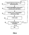
- Figure 6 shows the steps performed by light detection apparatus of Figure 4 to store measurements. Firstly, at step 270 the apparatus receives a waveform from a light detector 10 in the array of detectors. It extracts the measurements that it requires (step 272), as described above, and converts the dc measurement using the look-up table before storing the measurements. This is repeated for each of the light detectors (step 278).
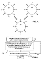
- Figure 7 shows two sets of readings returned by the light compass 17.
- Set 750 shows the readings for a first position of the cleaning device and 752 for a second position of the cleaning device.
- the numbers correspond to the converted measurements returned by the light detectors in each of the eight directions around the cleaning device.
- Figure 8 shows the steps in the method of comparing two sets of light compass measurements. A difference is calculated between the detector measurements for each detector direction, this difference being shown at 754 in Figure 7.
- the light detector can individually consider the dc (natural light) and ac (artificial light) components of the received light in this manner. However, it is preferred not to convert the measurements of ac light using the look-up table as the measurements tend to be lower than dc measurements and the conversion would unduly distort them.
- the result of this comparison process is an error metric indicative of the similarity of the two sets of readings taken at the two positions.
- An error metric is derived for each possible orientation of the two sets of measurements (eight in all.)
- the reason for comparing the two sets of measurements in different orientations is because although the two sets of measurements may have been taken while the vehicle was in the same position, the vehicle may not have been pointing in the same direction. By comparing the measurements in different orientations, a suitable match can be found under these conditions.
- the resulting set of error metrics can be weighted according to various criteria and finally compared with a threshold to decide whether a particular orientation of the two sets of measurements is good enough to represent a match.
- One particular application of light detection apparatus as described above is to help locate an autonomous vehicle, typically a robotic cleaning device such as a robotic vacuum cleaner, in a room by identifying when the light detected by the apparatus is the same or substantially the same as light previously detected by the light apparatus.
- the information received from the light detection apparatus in conjunction with information received from obstacle avoidance sensors, can then be used to navigate the autonomous vehicle around a room.
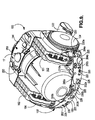
- Figure 9 shows a robotic, or autonomous, floor cleaning device in the form of a robotic vacuum cleaner 100 comprising a main body or supporting chassis 102, two driven wheels 104, a brushbar housing 122, two rechargeable batteries 161 and 162, a dust separating apparatus in the form of a dual cyclonic separator 152 of the type more fully described in EP-A-0042723, a user interface 144 and various sensors 202, 204, 206, 208, 210, 220, 230, 240, 250 which will be more fully described.
- the light detection apparatus, or light compass 17 is mounted on the upper face of the cleaning device 100. In this position, the light detection apparatus 17 has an unobstructed field-of-view around the cleaning device.
- the detecting devices within the light detection apparatus are arranged as shown in Figure 1E, with their field-of-view extending upwardly from the horizon in a vertical plane so that the detecting devices are not obstructed by parts of the cleaning device.
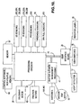
- Figure 10 shows a control circuit for the cleaning device of Figure 9.
- the circuit comprises two rechargeable batteries 161, 162, a battery and motor management system 41, a motor 50 for driving a suction fan, traction motors 43 for driving the left and right hand wheels 104 of the vacuum cleaner, a motor 28 for driving the brush bar of the vacuum cleaner and processing circuitry 23, which includes a microprocessor and field programmable gate arrays (FPGA).
- a user interface board 29 provides a plurality of user switches 75 by which a user can control the cleaning device and a plurality of indicator lamps 76 by which the cleaning device can indicate to the user.
- the user interface board also couples to the light detector 17, as the upper face of the cleaning device provides the light detector with an unobstructed view of the environment.
- a communications bus 70 couples the processing circuitry 23 to the battery and motor management system 41 and the user interface board 29. Measurements from each of the light detection devices 10 within the light detection apparatus 17 are carried along bus 70 to processing circuitry 23 where all of the above described processing is performed.
- the sets of light measurements are stored in memory 97 and the look-up table ( Figure 5B) is stored in a non-volatile memory 96.
- Control software for performing the processing of the light measurements made by the light detection devices, for comparing the measurements and for controlling navigation of the cleaning device is stored in memory 96 for execution by processing circuitry 23.
- the robotic vacuum cleaner is also equipped with a plurality of infra-red transmitters 210a, 220, 226, 230a and infra-red receivers 225, a plurality of ultrasonic transmitters 202a, 204a, 206a, 208a and ultrasonic receivers 202b, 204b, 206b, 208b, threshold detectors (95, Fig. 10) for detecting the presence of a portable threshold locator placed, for example, at the entrance to a room or at the edge of a staircase and one or more pyroelectric or passive infra-red (PIR) detectors 240a, 240b for detecting heat sources near to the cleaning device, such as animals and fires.
- PIR passive infra-red
- the four main ultrasonic receivers 202b, 204b, 206b, 208b face forwards, rearwards and to opposite sides of the robotic vacuum cleaner.
- the signals received by these receivers not only provide information representative of distance from a feature of the room or from an object in the room but the amplitude and width of the received signals vary according to the sensed size, shape and type of material of the object.
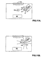
- Figures 11A and 11B show what information the device receives from its sensors. These Figures show the cleaning device 100 in a room that contains the obstacles of a table 400 and sofa 402.
- the cleaning device measures, using its light compass 17, light received from eight different directions (L1, L2, L3, L4, L5, L6, L7, L8). This combination of measurements has generally been found to be unique within a given room to within an area of several widths of the robotic device.
- the room in Figure 11 is illuminated by a combination of natural light from a window 702 and an artificial source 700. Light from the sources is reflected by objects 400, 402 and walls of the room before it reaches the light compass 17 on the cleaning device.
- the cleaning device also has the set of ultrasonic sensors 202, 204, 206, 208, shown located at the front, left, right and back of the cleaning device.
- Figure 11B shows the measurements that the ultrasonic sensors make.
- Each ultrasonic sensor provides a signal US1, US2, US3, US4 which is indicative of the distance of objects from the cleaning device.
- a combination of the light compass data L1..L8 and ultrasonic sensor data US1..US4 allows the cleaning device to uniquely identify its position within the room.
- Figures 12 and 13 illustrate one method of operating the robotic vacuum cleaner to clean a room.
- the method causes the cleaner to traverse the room in a generally spiralling manner.
- the cleaner is, typically, placed alongside a wall or freely in the room (position W, Fig. 12).
- a room feature (step 300; A, Fig. 12).
- this is a wall of the room or a major object or feature in the room.
- the cleaning device then moves forwardly along the edge of the room. This period is called the "perimeter scan", as the machine follows the perimeter of the room as closely as possible, the machine keeping the wall (or other obstacle) close to the left-hand side of the machine. This is shown as points A-H in Fig. 12).
- the machine keeps the wall close to the left-hand side of the machine as this is the side from which the cleaner head 122 protrudes.
- the various sensors on the cleaner detect obstacles in the room and other room features, such as comers of a room and fireplaces, and the processing circuitry 23 navigates the robotic vacuum cleaner in order to avoid any such obstacles and to change direction when a feature of a room is reached.
- the processing circuitry 23 stores information received from the light detector 17 and also from the four main ultrasonic receivers 202b, 204b, 206b, 208b in memory 97. This is the information shown in Figures 11A, 11B. These points are called "way points" (B, C, D.. Fig. 12).
- the processing circuitry 23 determines that the robotic vacuum cleaner has completed one traverse, or circuit, around the room (step 306) and is programmed to cause the robotic vacuum cleaner to step inwards by substantially one cleaner width.
- the cleaning device takes the new waypoint I', for use in matching at the end of the second circuit, rotates 90° to the right, and begins a second circuit.
- the processing circuitry 23 continues to store way point information and compares the information received from the light detector 17 and the four main receivers 202b, 204b, 206b, 208b with previously stored information (step 308).
- the cleaning device matches the two sets of light measurements at position T with position I' and moves inwardly again.
- the cleaner progresses around the room in a generally inwardly spiralling manner.
- the robotic vacuum cleaner If the robotic vacuum cleaner is initially placed in the middle of the room, it will travel until it finds a wall or obstacle. If it finds a wall it will then follow the path described above. If it finds a feature (such as a central fireplace) or an obstacle in the centre of the room, it will complete a circuit around that feature or obstacle and then follow a generally outwardly spiral path.
- arrays of light detectors can be provided so that a first array receives incident light up to a first angle a to the horizontal (say 50°), and a second array receives incident light between the first angle and a second angle b (perhaps 80°) to the horizontal.
- first angle a to the horizontal
- second angle b perhaps 80°
Landscapes
- Physics & Mathematics (AREA)
- Remote Sensing (AREA)
- Engineering & Computer Science (AREA)
- Radar, Positioning & Navigation (AREA)
- General Physics & Mathematics (AREA)
- Electromagnetism (AREA)
- Computer Networks & Wireless Communication (AREA)
- Acoustics & Sound (AREA)
- Control Of Position, Course, Altitude, Or Attitude Of Moving Bodies (AREA)
- Geophysics And Detection Of Objects (AREA)
- Length Measuring Devices By Optical Means (AREA)
- Electric Vacuum Cleaner (AREA)
- Cleaning In General (AREA)
- Gyroscopes (AREA)
- Measuring Pulse, Heart Rate, Blood Pressure Or Blood Flow (AREA)
Claims (28)
- Lichterfassungsvorrichtung für das Ermitteln der Stelle eines Körpers innerhalb einer Fläche, wobei die Vorrichtung aufweist:mindestens zwei Lichterfassungsgeräte für das Montieren am Körper, und die Licht aus der Umgebung, in der der Körper angeordnet ist, empfangen können, wobei die Geräte an entsprechenden Erfassungsstellen angeordnet sind, die winkelig um eine vertikale Achse herum beabstandet sind;eine Einrichtung für das Liefern einer Information, die für die Niveaus der mindestens zwei unterschiedlichen Lichtarten repräsentativ ist, die an jeder Erfassungsstelle empfangen werden; undeine Einrichtung für das Vergleichen der Information, die von der Lichterfassungsvorrichtung empfangen wird, mit der Information, die vorher von der Lichterfassungsvorrichtung empfangen und in einem Speicher gespeichert wurde, um so nachzuweisen, wenn das von der Lichterfassungsvorrichtung erfaßte Licht das gleiche oder im wesentlichen das gleiche ist wie das Licht, das vorher von der Lichterfassungsvorrichtung erfaßt wurde.
- Lichterfassungsvorrichtung nach Anspruch 1, bei der die Lichtarten Umgebungslicht, Glühlampenlicht und/oder Leuchtstofflampenlicht sind.
- Lichterfassungsvorrichtung nach Anspruch 1, bei der die Einrichtung für das Liefern einer Information das Signal von den Lichterfassungsgeräten filtert, um eine Information betreffs der unterschiedlichen Lichtarten zu erhalten.
- Lichterfassungsvorrichtung nach Anspruch 1, bei der die Einrichtung für das Liefern einer Information das Signal vom Lichterfassungsgerät über eine Zeitdauer digitalisiert, das digitalisierte Signal überwacht, um einen minimalen und maximalen Wert des Signals zu erhalten, und diese Werte verwendet, um eine Information zu erhalten, die auf Gleichstrom- und zeitvariable Lichtarten hinweist.
- Lichterfassungsvorrichtung nach Anspruch 1, bei der die Lichtarten Farben des Lichtes sind.
- Lichterfassungsvorrichtung nach Anspruch 5, bei der die Farben sind: rot, blau und grün oder magenta, gelb und zyan.
- Lichterfassungsvorrichtung nach Anspruch 5 oder 6, bei der das sichtbare Licht in eine Vielzahl von Farben getrennt wird, wobei jede Farbe von einer separaten Erfassungseinrichtung erfaßt wird.
- Lichterfassungsvorrichtung nach Anspruch 1, die separate Erfassungseinrichtungen für das Erfassen von sichtbarem und Infrarotlicht aufweist.
- Lichterfassungsvorrichtung nach einem der vorhergehenden Ansprüche, bei der die Stellen, an denen Licht empfangen wird, gleichwinkelig um die vertikale Achse herum beabstandet sind.
- Lichterfassungsvorrichtung nach einem der vorhergehenden Ansprüche, bei der die Lichterfassungsgeräte alle in einer gemeinsamen Ebene getragen werden.
- Lichterfassungsvorrichtung nach vorhergehenden Ansprüchen, bei der die Lichterfassungsgeräte Licht über einen Einfallsstrahlwinkel in einer vertikalen Ebene empfangen, die sich nach oben vom Horizont aus erstreckt.
- Lichterfassungsvorrichtung nach einem der vorhergehenden Ansprüche, bei der jedes Lichterfassungsgerät Licht über einen oder annähernd über einen Einfallsstrahlwinkel in einer ersten Ebene empfängt, die senkrecht zur vertikalen Achse verläuft, berechnet durch Dividieren von 360° durch die Anzahl der vorhandenen Lichterfassungsgeräte.
- Lichterfassungsvorrichtung nach einem der vorhergehenden Ansprüche, bei der ein Abschirmelement zwischen benachbarten Lichterfassungsgeräten positioniert ist.
- Lichterfassungsvorrichtung nach einem der vorhergehenden Ansprüche, bei der die Lichterfassungsgeräte eine ladungsgekoppelte Halbleitervorrichtungsanordnung bilden.
- Lichterfassungsvorrichtung nach einem der vorhergehenden Ansprüche, bei der die Lichterfassungsgeräte innerhalb eines Gehäuses für das Montieren auf dem Körper getragen werden.
- Selbständiges Gefährt, das aufweist: eine kraftbetriebene Einrichtung für das Bewegen des Gefährtes um eine Fläche herum; und ein Navigationssystem für das Identifizieren des Ortes des Gefährtes, wobei das Navigationssystem die Lichterfassungsvorrichtung nach einem der vorhergehenden Ansprüche umfaßt, um dem Gefährt zu gestatten, zu ermitteln, wenn es in eine gleiche Position in der Fläche zurückgekehrt ist.
- Selbständiges Gefährt nach Anspruch 16, bei dem die vertikale Achse der Lichterfassungsvorrichtung mittig vom Gefährt angeordnet ist.
- Selbständiges Gefährt nach Anspruch 16 oder 17, bei dem die Lichterfassungsvorrichtung auf einem obersten Teil des Körpers getragen wird.
- Selbständiges Gefährt nach einem der Ansprüche 16 bis 18 in der Form einer Roboterreinigungsvorrichtung.
- Selbständiges Gefährt nach Anspruch 19 in der Form eines Roboterstaubsaugers.
- Verfahren zum Ermitteln der Stelle eines Körpers innerhalb einer Fläche, das die folgenden Schritte aufweist:Verwenden von mindestens zwei Lichterfassungsgeräten, die am Körper montiert sind, um Licht aus der Umgebung aufzunehmen, in der der Körper angeordnet ist, wobei die Geräte an entsprechenden Erfassungsstellen angeordnet sind, die winkelig um eine vertikale Achse herum beabstandet sind;Erhalten einer Information, die für die Niveaus der mindestens zwei unterschiedlichen Lichtarten repräsentativ ist, die an jeder Ermittlungsstelle empfangen werden; undVergleichen der von der Lichterfassungsvorrichtung empfangenen Information mit der Information, die vorher von der Lichterfassungsvorrichtung empfangen und in einem Speicher gespeichert wurde, um so nachzuweisen, wenn das Licht, das mittels der Lichterfassungsvorrichtung erfaßt wird, das gleiche oder im wesentlichen das gleiche ist wie das Licht, das vorher von der Lichterfassungsvorrichtung erfaßt wurde.
- Selbständige Fußbodenreinigungsvorrichtung für das Reinigen einer Fußbodenfläche, die aufweist:kraftbetriebene Einrichtung für das Bewegen des Gefährtes um die Fußbodenfläche herum und ein Navigationssystem für das Identifizieren des Ortes des Gefährtes und für das Steuern der Bewegung der Reinigungsvorrichtung, worin das Navigationssystem eine Lichterfassungsvorrichtung umfaßt, die aufweist:mindestens zwei Lichterfassungsgeräte, die am Körper montiert sind, und die Licht aus der Umgebung, in der die Reinigungsvorrichtung angeordnet ist, empfangen können, wobei die Erfassungsgeräte an entsprechenden Lichterfassungsstellen angeordnet sind, die winkelig um eine vertikale Achse herum beabstandet sind;eine Einrichtung für das Liefern einer Information, die für die Niveaus der mindestens zwei unterschiedlichen Lichtarten repräsentativ ist, die an jeder Erfassungsstelle erfaßt werden; undeine Einrichtung für das Vergleichen der Information, die von der Lichterfassungsvorrichtung empfangen wird, mit der Information, die vorher von der Lichterfassungsvorrichtung empfangen und in einem Speicher gespeichert wurde, um so nachzuweisen, wenn das von der Lichterfassungsvorrichtung erfaßte Licht das gleiche oder im wesentlichen das gleiche ist wie das Licht, das vorher von der Lichterfassungsvorrichtung erfaßt wurde, was auf das Rückkehren der Reinigungsvorrichtung in eine gleiche Position in der Fläche hinweist.
- Selbständige Fußbodenreinigungsvorrichtung nach Anspruch 22, bei der das Navigationssystem angeordnet ist, um zu veranlassen, daß die Reinigungsvorrichtung ein spiralförmiges Muster des Bedeckens der Fußbodenfläche bewirkt, und ein Hinweis von der Lichterfassungsvorrichtung, daß die Reinigungsvorrichtung in eine gleiche Position in der Fläche zurückgekehrt ist, veranlaßt, daß sich die Reinigungsvorrichtung nach innen oder nach außen bewegt, um mit einem weiteren Kreislauf auf der Fußbodenfläche zu beginnen.
- Selbständige Fußbodenreinigungsvorrichtung nach Anspruch 22 oder 23, bei der die vertikale Achse der Lichterfassungsvorrichtung mittig vom Gefährt angeordnet ist.
- Selbständige Fußbodenreinigungsvorrichtung nach einem der Ansprüche 22 bis 24, bei der die Lichterfassungsvorrichtung auf einem obersten Teil des Körpers getragen wird.
- Selbständige Fußbodenreinigungsvorrichtung nach einem der Ansprüche 22 bis 25, bei der die Einrichtung für das Liefern einer Information eine Information liefert, die für mindestens zwei unterschiedliche Lichtarten repräsentativ ist, die an jeder Erfassungsstelle empfangen werden.
- Selbständige Fußbodenreinigungsvorrichtung nach einem der Ansprüche 22 bis 26 in der Form eines Roboterstaubsaugers.
- Verfahren zum Betätigen einer selbständigen Fußbodenreinigungsvorrichtung, um eine Fußbodenfläche zu reinigen, wobei die Reinigungsvorrichtung eine kraftbetriebene Einrichtung für das Bewegen des Gefährtes um die Fußbodenfläche herum und ein Navigationssystem für das Nachweisen der Stelle des Gefährtes und für das Steuern der Bewegung der Reinigungsvorrichtung aufweist, und worin das Navigationssystem eine Lichterfassungsvorrichtung umfaßt,
wobei das Verfahren die folgenden Schritte aufweist:Verwenden von mindestens zwei Lichterfassungsgeräten, die am Körper montiert sind, um Licht aus der Umgebung aufzunehmen, in der die Reinigungsvorrichtung angeordnet ist, wobei die Erfassungsgeräte an entsprechenden Lichterfassungsstellen angeordnet sind, die winkelig um eine vertikale Achse herum beabstandet sind;Erhalten einer Information, die für die Niveaus der mindestens zwei unterschiedlichen Lichtarten repräsentativ ist, die an jeder Ermittlungsstelle erfaßt werden; undVergleichen der von der Lichterfassungsvorrichtung empfangenen Information mit der Information, die vorher von der Lichterfassungsvorrichtung empfangen und in einem Speicher gespeichert wurde, um so nachzuweisen, wenn das Licht, das mittels der Lichterfassungsvorrichtung erfaßt wird, das gleiche oder im wesentlichen das gleiche ist wie das Licht, das vorher von der Lichterfassungsvorrichtung erfaßt wurde, was auf das Rückführen der Reinigungsvorrichtung in eine gleiche Position in der Fläche hinweist.
Applications Claiming Priority (3)
| Application Number | Priority Date | Filing Date | Title |
|---|---|---|---|
| GB9827771A GB2344884A (en) | 1998-12-18 | 1998-12-18 | Light Detection Apparatus - eg for a robotic cleaning device |
| GB9827771 | 1998-12-18 | ||
| PCT/GB1999/004092 WO2000038027A1 (en) | 1998-12-18 | 1999-12-06 | Light detection apparatus |
Publications (2)
| Publication Number | Publication Date |
|---|---|
| EP1149332A1 EP1149332A1 (de) | 2001-10-31 |
| EP1149332B1 true EP1149332B1 (de) | 2003-08-06 |
Family
ID=10844390
Family Applications (1)
| Application Number | Title | Priority Date | Filing Date |
|---|---|---|---|
| EP99958394A Expired - Lifetime EP1149332B1 (de) | 1998-12-18 | 1999-12-06 | Lichterfassungsvorrichtung |
Country Status (8)
| Country | Link |
|---|---|
| US (1) | US6590222B1 (de) |
| EP (1) | EP1149332B1 (de) |
| JP (1) | JP4819221B2 (de) |
| AT (1) | ATE246818T1 (de) |
| AU (1) | AU1576800A (de) |
| DE (1) | DE69910262T2 (de) |
| GB (1) | GB2344884A (de) |
| WO (1) | WO2000038027A1 (de) |
Cited By (3)
| Publication number | Priority date | Publication date | Assignee | Title |
|---|---|---|---|---|
| US7237298B2 (en) | 2003-09-19 | 2007-07-03 | Royal Appliance Mfg. Co. | Sensors and associated methods for controlling a vacuum cleaner |
| US7424766B2 (en) | 2003-09-19 | 2008-09-16 | Royal Appliance Mfg. Co. | Sensors and associated methods for controlling a vacuum cleaner |
| US7599758B2 (en) | 2003-09-19 | 2009-10-06 | Royal Appliance Mfg. Co. | Sensors and associated methods for controlling a vacuum cleaner |
Families Citing this family (56)
| Publication number | Priority date | Publication date | Assignee | Title |
|---|---|---|---|---|
| US8412377B2 (en) | 2000-01-24 | 2013-04-02 | Irobot Corporation | Obstacle following sensor scheme for a mobile robot |
| US8788092B2 (en) | 2000-01-24 | 2014-07-22 | Irobot Corporation | Obstacle following sensor scheme for a mobile robot |
| US6956348B2 (en) | 2004-01-28 | 2005-10-18 | Irobot Corporation | Debris sensor for cleaning apparatus |
| US6690134B1 (en) | 2001-01-24 | 2004-02-10 | Irobot Corporation | Method and system for robot localization and confinement |
| US7571511B2 (en) | 2002-01-03 | 2009-08-11 | Irobot Corporation | Autonomous floor-cleaning robot |
| US6883201B2 (en) | 2002-01-03 | 2005-04-26 | Irobot Corporation | Autonomous floor-cleaning robot |
| US8396592B2 (en) | 2001-06-12 | 2013-03-12 | Irobot Corporation | Method and system for multi-mode coverage for an autonomous robot |
| US7429843B2 (en) * | 2001-06-12 | 2008-09-30 | Irobot Corporation | Method and system for multi-mode coverage for an autonomous robot |
| AU2002341358A1 (en) | 2001-09-26 | 2003-04-07 | Friendly Robotics Ltd. | Robotic vacuum cleaner |
| IL145680A0 (en) | 2001-09-26 | 2002-06-30 | Friendly Robotics Ltd | Robotic vacuum cleaner |
| US9128486B2 (en) | 2002-01-24 | 2015-09-08 | Irobot Corporation | Navigational control system for a robotic device |
| FR2840541B1 (fr) * | 2002-06-11 | 2005-02-25 | Janick Simeray | Jouet mobile motorise a telecommande |
| US8428778B2 (en) | 2002-09-13 | 2013-04-23 | Irobot Corporation | Navigational control system for a robotic device |
| US8386081B2 (en) | 2002-09-13 | 2013-02-26 | Irobot Corporation | Navigational control system for a robotic device |
| US20050010331A1 (en) * | 2003-03-14 | 2005-01-13 | Taylor Charles E. | Robot vacuum with floor type modes |
| US20040200505A1 (en) * | 2003-03-14 | 2004-10-14 | Taylor Charles E. | Robot vac with retractable power cord |
| US7801645B2 (en) * | 2003-03-14 | 2010-09-21 | Sharper Image Acquisition Llc | Robotic vacuum cleaner with edge and object detection system |
| US7805220B2 (en) * | 2003-03-14 | 2010-09-28 | Sharper Image Acquisition Llc | Robot vacuum with internal mapping system |
| US20040211444A1 (en) * | 2003-03-14 | 2004-10-28 | Taylor Charles E. | Robot vacuum with particulate detector |
| DE10357636B4 (de) * | 2003-12-10 | 2013-05-08 | Vorwerk & Co. Interholding Gmbh | Selbsttätig verfahrbares Bodenstaub-Aufsammelgerät |
| US7332890B2 (en) | 2004-01-21 | 2008-02-19 | Irobot Corporation | Autonomous robot auto-docking and energy management systems and methods |
| US20060020369A1 (en) * | 2004-03-11 | 2006-01-26 | Taylor Charles E | Robot vacuum cleaner |
| KR101214723B1 (ko) | 2004-06-24 | 2012-12-24 | 아이로보트 코퍼레이션 | 자동 로봇 장치용의 원격 제어 스케줄러 및 방법 |
| US7706917B1 (en) | 2004-07-07 | 2010-04-27 | Irobot Corporation | Celestial navigation system for an autonomous robot |
| US8972052B2 (en) | 2004-07-07 | 2015-03-03 | Irobot Corporation | Celestial navigation system for an autonomous vehicle |
| KR100641113B1 (ko) * | 2004-07-30 | 2006-11-02 | 엘지전자 주식회사 | 이동로봇 및 그의 이동제어방법 |
| US7620476B2 (en) | 2005-02-18 | 2009-11-17 | Irobot Corporation | Autonomous surface cleaning robot for dry cleaning |
| ES2346343T3 (es) | 2005-02-18 | 2010-10-14 | Irobot Corporation | Robot autonomo de limpieza de superficies para una limpieza en seco y en mojado. |
| US8392021B2 (en) | 2005-02-18 | 2013-03-05 | Irobot Corporation | Autonomous surface cleaning robot for wet cleaning |
| US8930023B2 (en) | 2009-11-06 | 2015-01-06 | Irobot Corporation | Localization by learning of wave-signal distributions |
| KR101300492B1 (ko) | 2005-12-02 | 2013-09-02 | 아이로보트 코퍼레이션 | 커버리지 로봇 이동성 |
| EP2829939B1 (de) | 2005-12-02 | 2019-11-13 | iRobot Corporation | Roboternavigationssystem mit autonomer Abdeckung |
| US8584305B2 (en) | 2005-12-02 | 2013-11-19 | Irobot Corporation | Modular robot |
| EP2816434A3 (de) | 2005-12-02 | 2015-01-28 | iRobot Corporation | Roboter mit autonomem Wirkungsbereich |
| EP2533120B1 (de) | 2005-12-02 | 2019-01-16 | iRobot Corporation | Robotersystem |
| US8528157B2 (en) | 2006-05-19 | 2013-09-10 | Irobot Corporation | Coverage robots and associated cleaning bins |
| US8417383B2 (en) | 2006-05-31 | 2013-04-09 | Irobot Corporation | Detecting robot stasis |
| ES2559128T3 (es) | 2007-05-09 | 2016-02-10 | Irobot Corporation | Robot autónomo de cubrimiento compacto |
| KR100919698B1 (ko) * | 2007-08-14 | 2009-09-29 | 포항공과대학교 산학협력단 | 로봇청소기를 이용한 청소방법 |
| CN101409490B (zh) * | 2007-10-08 | 2013-08-14 | 德昌电机股份有限公司 | 电动机 |
| TW201116383A (en) * | 2009-11-10 | 2011-05-16 | Micro Star Int Co Ltd | Control method and cleaning robot utilizing the same |
| CN102092048A (zh) * | 2009-12-09 | 2011-06-15 | 恩斯迈电子(深圳)有限公司 | 控制方法及清扫机器人装置 |
| CN102138769B (zh) * | 2010-01-28 | 2014-12-24 | 深圳先进技术研究院 | 清洁机器人及其清扫方法 |
| KR101497197B1 (ko) | 2010-02-16 | 2015-02-27 | 아이로보트 코퍼레이션 | 진공 브러쉬 |
| CN103251358A (zh) * | 2012-02-16 | 2013-08-21 | 恩斯迈电子(深圳)有限公司 | 扫地机器人的控制方法 |
| TWM435906U (de) * | 2012-04-06 | 2012-08-21 | Uni Ring Tech Co Ltd | |
| US8878114B2 (en) | 2012-08-16 | 2014-11-04 | Nanohmics, Inc. | Apparatus and methods for locating source of and analyzing electromagnetic radiation |
| CN104245244B (zh) | 2012-09-21 | 2016-01-20 | 艾罗伯特公司 | 移动机器人上的接近度感测 |
| TWM451103U (zh) * | 2012-10-30 | 2013-04-21 | Agait Technology Corp | 行走裝置 |
| JP6827758B2 (ja) | 2016-10-12 | 2021-02-10 | 東芝映像ソリューション株式会社 | 移動式アシスト装置及び移動式アシスト方法 |
| JP6709984B2 (ja) * | 2016-11-30 | 2020-06-17 | パナソニックIpマネジメント株式会社 | 赤外線検出装置 |
| CN106679684A (zh) * | 2016-12-27 | 2017-05-17 | 湖南挚新科技发展有限公司 | 自动化作业设备路径规划方法与系统 |
| US11284702B2 (en) | 2017-05-15 | 2022-03-29 | Sharkninja Operating Llc | Side brush with bristles at different lengths and/or angles for use in a robot cleaner and side brush deflectors |
| CN108143364B (zh) * | 2017-12-28 | 2021-02-19 | 湖南格兰博智能科技有限责任公司 | 一种自移动清洁机器人清洁地图区域划分的方法 |
| US10732060B2 (en) * | 2018-08-15 | 2020-08-04 | X Development Llc | Force/torque sensor with hardstops to limit overloading a flexure |
| US12089793B2 (en) * | 2018-12-07 | 2024-09-17 | Yujin Robot Co., Ltd. | Autonomously traveling mobile robot and traveling control method therefor |
Family Cites Families (12)
| Publication number | Priority date | Publication date | Assignee | Title |
|---|---|---|---|---|
| US4751658A (en) * | 1986-05-16 | 1988-06-14 | Denning Mobile Robotics, Inc. | Obstacle avoidance system |
| JPH01180010A (ja) * | 1988-01-08 | 1989-07-18 | Sanyo Electric Co Ltd | 移動車 |
| US5170352A (en) * | 1990-05-07 | 1992-12-08 | Fmc Corporation | Multi-purpose autonomous vehicle with path plotting |
| US5165064A (en) * | 1991-03-22 | 1992-11-17 | Cyberotics, Inc. | Mobile robot guidance and navigation system |
| US5279672A (en) * | 1992-06-29 | 1994-01-18 | Windsor Industries, Inc. | Automatic controlled cleaning machine |
| US5440216A (en) * | 1993-06-08 | 1995-08-08 | Samsung Electronics Co., Ltd. | Robot cleaner |
| US6059657A (en) * | 1994-06-22 | 2000-05-09 | Oh; Ketsu | Game machine |
| US5635724A (en) * | 1995-06-07 | 1997-06-03 | Intecolor | Method and apparatus for detecting the location of an object on a surface |
| GB2307810A (en) * | 1995-12-02 | 1997-06-04 | Roy Michael Ashley | Parking aid |
| JP3866328B2 (ja) * | 1996-06-06 | 2007-01-10 | 富士重工業株式会社 | 車両周辺立体物認識装置 |
| JPH10103923A (ja) * | 1996-09-30 | 1998-04-24 | Sony Corp | 位置検出装置及び方法並びにロボツト装置 |
| JP2001508572A (ja) * | 1997-01-22 | 2001-06-26 | シーメンス アクチエンゲゼルシヤフト | 自立移動式装置のドッキングの位置決め方法および装置 |
-
1998
- 1998-12-18 GB GB9827771A patent/GB2344884A/en not_active Withdrawn
-
1999
- 1999-12-06 US US09/868,493 patent/US6590222B1/en not_active Expired - Fee Related
- 1999-12-06 EP EP99958394A patent/EP1149332B1/de not_active Expired - Lifetime
- 1999-12-06 DE DE69910262T patent/DE69910262T2/de not_active Expired - Fee Related
- 1999-12-06 JP JP2000590021A patent/JP4819221B2/ja not_active Expired - Fee Related
- 1999-12-06 WO PCT/GB1999/004092 patent/WO2000038027A1/en not_active Ceased
- 1999-12-06 AT AT99958394T patent/ATE246818T1/de not_active IP Right Cessation
- 1999-12-06 AU AU15768/00A patent/AU1576800A/en not_active Abandoned
Cited By (3)
| Publication number | Priority date | Publication date | Assignee | Title |
|---|---|---|---|---|
| US7237298B2 (en) | 2003-09-19 | 2007-07-03 | Royal Appliance Mfg. Co. | Sensors and associated methods for controlling a vacuum cleaner |
| US7424766B2 (en) | 2003-09-19 | 2008-09-16 | Royal Appliance Mfg. Co. | Sensors and associated methods for controlling a vacuum cleaner |
| US7599758B2 (en) | 2003-09-19 | 2009-10-06 | Royal Appliance Mfg. Co. | Sensors and associated methods for controlling a vacuum cleaner |
Also Published As
| Publication number | Publication date |
|---|---|
| ATE246818T1 (de) | 2003-08-15 |
| DE69910262D1 (de) | 2003-09-11 |
| JP4819221B2 (ja) | 2011-11-24 |
| GB9827771D0 (en) | 1999-02-10 |
| US6590222B1 (en) | 2003-07-08 |
| WO2000038027A1 (en) | 2000-06-29 |
| GB2344884A (en) | 2000-06-21 |
| JP2002533687A (ja) | 2002-10-08 |
| AU1576800A (en) | 2000-07-12 |
| EP1149332A1 (de) | 2001-10-31 |
| DE69910262T2 (de) | 2004-07-01 |
Similar Documents
| Publication | Publication Date | Title |
|---|---|---|
| US6590222B1 (en) | Light detection apparatus | |
| US9968233B2 (en) | Automatically driven cleaning device | |
| US6968592B2 (en) | Self-running vacuum cleaner | |
| US9229454B1 (en) | Autonomous mobile robot system | |
| EP3417755B1 (de) | Autonomes fahrzeug | |
| EP3308911B1 (de) | Mobiler roboter und verfahren zur steuerung davon | |
| US6671592B1 (en) | Autonomous vehicular appliance, especially vacuum cleaner | |
| AU767206B2 (en) | Indicator for a robotic machine | |
| EP3459691A1 (de) | Robotischer staubsauger | |
| EP3432107A1 (de) | Reinigungsroboter und steuerungsverfahren dafür | |
| KR102032516B1 (ko) | 이동 로봇 및 그 제어방법 | |
| KR102201144B1 (ko) | 이동 로봇 및 그 제어방법 | |
| US20050046373A1 (en) | Autonomous machine | |
| GB2398195A (en) | Location mark detecting method for a robotic cleaner and a robotic cleaner using the method | |
| US20190223679A1 (en) | Debris monitoring | |
| WO2000038025A1 (en) | Improvements in or relating to floor cleaning devices | |
| KR102314537B1 (ko) | 이동 로봇 및 그 제어방법 | |
| WO2018131856A1 (ko) | 청소기 및 그 제어방법 | |
| CN111948661A (zh) | 一种自移动设备及探测装置 | |
| WO2019212174A1 (ko) | 인공지능 청소기 및 그 제어방법 | |
| KR102711192B1 (ko) | 이동 로봇 및 그 제어방법 | |
| US20190204442A1 (en) | Detection assembly, cleaning robot and method and system for detecting walking condition thereof | |
| KR102328595B1 (ko) | 이동 로봇 및 이동 로봇의 제어방법 | |
| TW434468B (en) | Light detection apparatus | |
| KR100722762B1 (ko) | 로봇 청소기의 장애물 형태 감지 장치 및 그 방법 |
Legal Events
| Date | Code | Title | Description |
|---|---|---|---|
| PUAI | Public reference made under article 153(3) epc to a published international application that has entered the european phase |
Free format text: ORIGINAL CODE: 0009012 |
|
| 17P | Request for examination filed |
Effective date: 20010605 |
|
| AK | Designated contracting states |
Kind code of ref document: A1 Designated state(s): AT BE CH CY DE DK ES FI FR GB GR IE IT LI LU MC NL PT SE |
|
| AX | Request for extension of the european patent |
Free format text: AL;LT;LV;MK;RO;SI |
|
| GRAG | Despatch of communication of intention to grant |
Free format text: ORIGINAL CODE: EPIDOS AGRA |
|
| 17Q | First examination report despatched |
Effective date: 20020625 |
|
| GRAG | Despatch of communication of intention to grant |
Free format text: ORIGINAL CODE: EPIDOS AGRA |
|
| GRAH | Despatch of communication of intention to grant a patent |
Free format text: ORIGINAL CODE: EPIDOS IGRA |
|
| GRAG | Despatch of communication of intention to grant |
Free format text: ORIGINAL CODE: EPIDOS AGRA |
|
| GRAH | Despatch of communication of intention to grant a patent |
Free format text: ORIGINAL CODE: EPIDOS IGRA |
|
| GRAA | (expected) grant |
Free format text: ORIGINAL CODE: 0009210 |
|
| AK | Designated contracting states |
Designated state(s): AT BE CH CY DE DK ES FI FR GB GR IE IT LI LU MC NL PT SE |
|
| PG25 | Lapsed in a contracting state [announced via postgrant information from national office to epo] |
Ref country code: NL Free format text: LAPSE BECAUSE OF FAILURE TO SUBMIT A TRANSLATION OF THE DESCRIPTION OR TO PAY THE FEE WITHIN THE PRESCRIBED TIME-LIMIT Effective date: 20030806 Ref country code: LI Free format text: LAPSE BECAUSE OF FAILURE TO SUBMIT A TRANSLATION OF THE DESCRIPTION OR TO PAY THE FEE WITHIN THE PRESCRIBED TIME-LIMIT Effective date: 20030806 Ref country code: IT Free format text: LAPSE BECAUSE OF FAILURE TO SUBMIT A TRANSLATION OF THE DESCRIPTION OR TO PAY THE FEE WITHIN THE PRE;WARNING: LAPSES OF ITALIAN PATENTS WITH EFFECTIVE DATE BEFORE 2007 MAY HAVE OCCURRED AT ANY TIME BEFORE 2007. THE CORRECT EFFECTIVE DATE MAY BE DIFFERENT FROM THE ONE RECORDED.SCRIBED TIME-LIMIT Effective date: 20030806 Ref country code: FI Free format text: LAPSE BECAUSE OF FAILURE TO SUBMIT A TRANSLATION OF THE DESCRIPTION OR TO PAY THE FEE WITHIN THE PRESCRIBED TIME-LIMIT Effective date: 20030806 Ref country code: CH Free format text: LAPSE BECAUSE OF FAILURE TO SUBMIT A TRANSLATION OF THE DESCRIPTION OR TO PAY THE FEE WITHIN THE PRESCRIBED TIME-LIMIT Effective date: 20030806 Ref country code: BE Free format text: LAPSE BECAUSE OF FAILURE TO SUBMIT A TRANSLATION OF THE DESCRIPTION OR TO PAY THE FEE WITHIN THE PRESCRIBED TIME-LIMIT Effective date: 20030806 Ref country code: AT Free format text: LAPSE BECAUSE OF FAILURE TO SUBMIT A TRANSLATION OF THE DESCRIPTION OR TO PAY THE FEE WITHIN THE PRESCRIBED TIME-LIMIT Effective date: 20030806 |
|
| REG | Reference to a national code |
Ref country code: GB Ref legal event code: FG4D |
|
| REG | Reference to a national code |
Ref country code: CH Ref legal event code: EP |
|
| REG | Reference to a national code |
Ref country code: IE Ref legal event code: FG4D |
|
| REF | Corresponds to: |
Ref document number: 69910262 Country of ref document: DE Date of ref document: 20030911 Kind code of ref document: P |
|
| PG25 | Lapsed in a contracting state [announced via postgrant information from national office to epo] |
Ref country code: SE Free format text: LAPSE BECAUSE OF FAILURE TO SUBMIT A TRANSLATION OF THE DESCRIPTION OR TO PAY THE FEE WITHIN THE PRESCRIBED TIME-LIMIT Effective date: 20031106 Ref country code: GR Free format text: LAPSE BECAUSE OF FAILURE TO SUBMIT A TRANSLATION OF THE DESCRIPTION OR TO PAY THE FEE WITHIN THE PRESCRIBED TIME-LIMIT Effective date: 20031106 Ref country code: DK Free format text: LAPSE BECAUSE OF FAILURE TO SUBMIT A TRANSLATION OF THE DESCRIPTION OR TO PAY THE FEE WITHIN THE PRESCRIBED TIME-LIMIT Effective date: 20031106 |
|
| PG25 | Lapsed in a contracting state [announced via postgrant information from national office to epo] |
Ref country code: ES Free format text: LAPSE BECAUSE OF FAILURE TO SUBMIT A TRANSLATION OF THE DESCRIPTION OR TO PAY THE FEE WITHIN THE PRESCRIBED TIME-LIMIT Effective date: 20031117 |
|
| NLV1 | Nl: lapsed or annulled due to failure to fulfill the requirements of art. 29p and 29m of the patents act | ||
| PG25 | Lapsed in a contracting state [announced via postgrant information from national office to epo] |
Ref country code: LU Free format text: LAPSE BECAUSE OF NON-PAYMENT OF DUE FEES Effective date: 20031206 Ref country code: CY Free format text: LAPSE BECAUSE OF FAILURE TO SUBMIT A TRANSLATION OF THE DESCRIPTION OR TO PAY THE FEE WITHIN THE PRESCRIBED TIME-LIMIT Effective date: 20031206 |
|
| PG25 | Lapsed in a contracting state [announced via postgrant information from national office to epo] |
Ref country code: IE Free format text: LAPSE BECAUSE OF NON-PAYMENT OF DUE FEES Effective date: 20031208 |
|
| PG25 | Lapsed in a contracting state [announced via postgrant information from national office to epo] |
Ref country code: MC Free format text: LAPSE BECAUSE OF NON-PAYMENT OF DUE FEES Effective date: 20031231 |
|
| PG25 | Lapsed in a contracting state [announced via postgrant information from national office to epo] |
Ref country code: PT Free format text: LAPSE BECAUSE OF FAILURE TO SUBMIT A TRANSLATION OF THE DESCRIPTION OR TO PAY THE FEE WITHIN THE PRESCRIBED TIME-LIMIT Effective date: 20040106 |
|
| REG | Reference to a national code |
Ref country code: CH Ref legal event code: PL |
|
| ET | Fr: translation filed | ||
| PLBE | No opposition filed within time limit |
Free format text: ORIGINAL CODE: 0009261 |
|
| STAA | Information on the status of an ep patent application or granted ep patent |
Free format text: STATUS: NO OPPOSITION FILED WITHIN TIME LIMIT |
|
| 26N | No opposition filed |
Effective date: 20040507 |
|
| REG | Reference to a national code |
Ref country code: IE Ref legal event code: MM4A |
|
| REG | Reference to a national code |
Ref country code: GB Ref legal event code: 732E |
|
| REG | Reference to a national code |
Ref country code: FR Ref legal event code: TP |
|
| PGFP | Annual fee paid to national office [announced via postgrant information from national office to epo] |
Ref country code: DE Payment date: 20090202 Year of fee payment: 10 |
|
| PGFP | Annual fee paid to national office [announced via postgrant information from national office to epo] |
Ref country code: FR Payment date: 20081217 Year of fee payment: 10 |
|
| REG | Reference to a national code |
Ref country code: FR Ref legal event code: ST Effective date: 20100831 |
|
| PG25 | Lapsed in a contracting state [announced via postgrant information from national office to epo] |
Ref country code: FR Free format text: LAPSE BECAUSE OF NON-PAYMENT OF DUE FEES Effective date: 20091231 |
|
| PG25 | Lapsed in a contracting state [announced via postgrant information from national office to epo] |
Ref country code: DE Free format text: LAPSE BECAUSE OF NON-PAYMENT OF DUE FEES Effective date: 20100701 |
|
| PGFP | Annual fee paid to national office [announced via postgrant information from national office to epo] |
Ref country code: GB Payment date: 20121227 Year of fee payment: 14 |
|
| GBPC | Gb: european patent ceased through non-payment of renewal fee |
Effective date: 20131206 |
|
| PG25 | Lapsed in a contracting state [announced via postgrant information from national office to epo] |
Ref country code: GB Free format text: LAPSE BECAUSE OF NON-PAYMENT OF DUE FEES Effective date: 20131206 |