EP1149952A2 - Aussenschallschutzwand - Google Patents
Aussenschallschutzwand Download PDFInfo
- Publication number
- EP1149952A2 EP1149952A2 EP01810385A EP01810385A EP1149952A2 EP 1149952 A2 EP1149952 A2 EP 1149952A2 EP 01810385 A EP01810385 A EP 01810385A EP 01810385 A EP01810385 A EP 01810385A EP 1149952 A2 EP1149952 A2 EP 1149952A2
- Authority
- EP
- European Patent Office
- Prior art keywords
- longitudinal grooves
- wooden planks
- protective wall
- wooden
- longitudinal
- Prior art date
- Legal status (The legal status is an assumption and is not a legal conclusion. Google has not performed a legal analysis and makes no representation as to the accuracy of the status listed.)
- Withdrawn
Links
Images


Classifications
-
- E—FIXED CONSTRUCTIONS
- E01—CONSTRUCTION OF ROADS, RAILWAYS, OR BRIDGES
- E01F—ADDITIONAL WORK, SUCH AS EQUIPPING ROADS OR THE CONSTRUCTION OF PLATFORMS, HELICOPTER LANDING STAGES, SIGNS, SNOW FENCES, OR THE LIKE
- E01F8/00—Arrangements for absorbing or reflecting air-transmitted noise from road or railway traffic
- E01F8/0005—Arrangements for absorbing or reflecting air-transmitted noise from road or railway traffic used in a wall type arrangement
- E01F8/0023—Details, e.g. foundations
-
- E—FIXED CONSTRUCTIONS
- E01—CONSTRUCTION OF ROADS, RAILWAYS, OR BRIDGES
- E01F—ADDITIONAL WORK, SUCH AS EQUIPPING ROADS OR THE CONSTRUCTION OF PLATFORMS, HELICOPTER LANDING STAGES, SIGNS, SNOW FENCES, OR THE LIKE
- E01F8/00—Arrangements for absorbing or reflecting air-transmitted noise from road or railway traffic
- E01F8/0005—Arrangements for absorbing or reflecting air-transmitted noise from road or railway traffic used in a wall type arrangement
- E01F8/0011—Plank-like elements
-
- E—FIXED CONSTRUCTIONS
- E01—CONSTRUCTION OF ROADS, RAILWAYS, OR BRIDGES
- E01F—ADDITIONAL WORK, SUCH AS EQUIPPING ROADS OR THE CONSTRUCTION OF PLATFORMS, HELICOPTER LANDING STAGES, SIGNS, SNOW FENCES, OR THE LIKE
- E01F8/00—Arrangements for absorbing or reflecting air-transmitted noise from road or railway traffic
- E01F8/0005—Arrangements for absorbing or reflecting air-transmitted noise from road or railway traffic used in a wall type arrangement
- E01F8/0047—Arrangements for absorbing or reflecting air-transmitted noise from road or railway traffic used in a wall type arrangement with open cavities, e.g. for covering sunken roads
- E01F8/0076—Cellular, e.g. as wall facing
Definitions
- the invention relates to an external sound barrier on traffic routes, Construction sites and noisy manufacturing, operating, sports or entertainment facilities outdoors.
- External noise barriers are used in particular along highways and Roads are set up more and more often, also in cooperation with piled-up ones Ramparts. These protective measures are also used by others Traffic routes, such as railroad lines, used to serve local residents to protect against excessive noise. Also interest groups and organizations increasingly demand such environmental protection measures Dimensions.
- the effect of exterior soundproof walls is based on reflection and / or Absorption properties of the incident sound waves. Depending on the design the soundproof walls outweigh the reflection or absorption component. For soundproof walls with a closed, smooth surface a practically complete reflection of the sound waves instead, for example at Metal, glass, stone and / or concrete walls.
- Suitable absorption materials are in particular fibrous materials, such as glass or rock wool, as well as open-cell soft foams, in particular made of plastic.
- Exterior sound barriers based on the absorption principle have in usually two disadvantages, on the one hand they are because of their complex structure expensive and complex in terms of maintenance, and on the other hand because of materials used little ecological.
- the present invention has for its object an inexpensive To create external sound barrier of the type mentioned, which on is based on a simple basic concept that is easy to assemble and disassemble has the necessary weather resistance and all environmental protection requirements Fulfills.
- the protective wall solid wooden planks with longitudinal, undercut on at least one side and / or formed as oblique slots longitudinal grooves, which in the direction the noise source (s) are open.
- Wood is a natural building material that has always been used, which today is pushed into the background for various reasons, in particular in civil engineering. In the event of recurring storm damage, especially from such catastrophic proportions, unforeseeable emerge in the forests Quantities of fall timber without sufficient direct and concrete usage prospects in the immediate vicinity.
- the wooden planks used according to the invention for external noise barriers offer a welcome in such situations Possibility of use. This is especially because it is also inferior Wood qualities can definitely serve their purpose. For this fall wood, but of course also from other wood, wooden planks are made by Rule 1 to 2 m in length, 0.1 to 0.2 m in width and 0.05 to 0.15 m in thickness. In special Cases can easily be made from these standard masses as needed be deviated.
- the outside noise barrier according to the invention is multifunctional. It works at the same time as security protection, for example along traffic routes, as Privacy protection, for example at a manufacturing facility, and / or as dirt protection, especially again along traffic routes.
- the outside noise barrier offers residents more quality of life thanks to the lower noise level, but also because of the lower exhaust emissions, a privacy screen for the outside living area, etc.
- Immediate bumps on external noise barriers can at most Gain the surrounding area by easily adding a to this protective wall Filling can take place, usually up to about 50 cm.
- the bulkhead can still perform its soundproofing function unchanged.
- the depth of the longitudinal grooves is preferably 30 to 70% of the thickness of the Wooden planks. These in turn are massively developed, especially because of the better sound absorption, with a backfill also because of the mechanical Strength.
- a simple variant of the invention consists of slanted slots made from the wooden plank mill out, which normally have parallel side walls.
- the slanted slots are preferably at an angle to the wooden surface from 30 to 60 °.
- the longitudinal grooves be at least partially lined or foamed with a fleece, the latter preferably with open-pore plastic foam.
- the wooden plank In the area between the longitudinal grooves, the wooden plank preferably remains raw Sawing condition, so it is no longer mechanically processed, for example by planing.
- the roughened structure of the surface promotes sound absorption. At most, a corresponding one is used against weather influences Protective treatment performed.
- the area between the longitudinal grooves can also pass through a sound absorbing layer may be covered, for example by application of a fleece.
- the wooden planks are expediently horizontal or almost horizontal, i.e. With a deviation from the horizontal of up to about 5 °.
- a Slightly inclined arrangement of the wooden planks has the advantage that none or less water bags can form in an undercut groove.
- the wooden planks can of course can also be arranged vertically or in any inclined position.
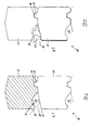
- two wooden planks 12 lying one on top of the other on the longitudinal side are one External sound barrier 10, which have a thickness d of 10 cm.
- the two Wooden planks 12 are anchored to each other by the lower one present trapezoidal, longitudinal comb 14, the upper one corresponding, also has trapezoidal anchoring groove 16.
- the plane of the two wooden planks lying on top of one another is also the plane of symmetry S of an undercut longitudinal groove 18, which in cross section Tulip shape is formed.
- the relatively wide entrance slot for the undercut longitudinal groove 18 has a chamfer on both sides in the opening area 20 22.
- a noise source Q moving along the exterior sound barrier 10 transmits sound waves 24 indicated by dashed lines.
- the noise source Q moving along the outside noise barrier 10 reaches its maximum effect on the longitudinal groove 18 when driving through the Plane of symmetry S.
- Fig. 1 are the sound waves emitted in this position 24 of the noise source Q indicated by dashed lines.
- 2 is the relevant one Situation before reaching the symmetry plane S is shown in dashed lines.
- the depth t of a longitudinal groove 18 according to FIGS. 1, 2 is approximately 5 cm, that is approximately half the thickness d of the wooden planks 12.
- the longitudinal groove 18 is in the lower region wedge-shaped, with a running with respect to the plane of symmetry S. Angle ⁇ less than 45 °.
- the wedge-shaped narrowing is designed thus the sound waves incident approximately parallel to the plane of symmetry S. 24 after double reflection not directly through the input slot 20 emerge, as would be the case at an angle ⁇ of 45 °. In all cases the reflected, emerging again from the input slot 20 Sound waves 24 in the shape of a cylinder jacket. However, their intensity will decrease any reflection inside the longitudinal groove 18 is further reduced.
- the wooden planks can be found at positions A and B. 12 a further longitudinal groove 18 can be left out. This corresponds in their geometric shape of the drawn longitudinal groove 18, but is not in the superimposed long sides but from the wooden planks 12 themselves recessed.
- the upper wooden plank 12 is angled like a roof.
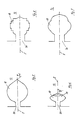
- FIG. 5 shows a wooden plank 12 according to position A or B of FIG. 1 recessed, undercut longitudinal groove 18.
- the recess 18 is almost cylindrical in shape, but goes in a wedge shape in the rear area an angle ⁇ of more than 45 °.
- a longitudinal groove 18 according to FIG. 6 is in its basic cross-sectional shape roughly elliptical, but the longitudinal groove is in the rearmost area 18 again in wedge shape.
- the angle ⁇ is about 70 ° here.
- a wedge shape is used in the rear area, so more favorable reflection properties arise, as was the case before Description of FIGS. 1 and 2 is discussed in detail.
- the longitudinal groove 18 shown in FIG. 7 is designed somewhat more complicated, it points in essentially a cross-sectional tree or flower shape, again with the blunt wedge in the rear area. More complicated forms have one more favorable reflection behavior, the penetrating sound waves 24 (Fig. 1 to 4) are rather retained in the undercut longitudinal groove 18, i.e. more often reflected. For this reason, the input slot 20 can also be left wider be what increases the effect of the external sound barrier 10 overall.
- Fig. 8 is an extremely structured Shape shown.
- Figures 9 to 12 show one of many options for mounting the wooden planks 12 for the formation of external soundproof walls 10 (Fig. 13, 14).
- a variant, not shown, is the best known mounting of the end faces in H profiles.
- Right-angled recesses 28 are made from the end faces of the wooden planks 12 formed which receive a square square tube as a support profile 30.
- a console 32 is shown, which as a square Square tube formed support profile 30 welded to a base plate 34 which, in turn, has four screw holes with a concrete foundation is screwable. Dashed is a telescopic extendable Extension 31 shown.
- the 4 mm thick wall of the support profile 30 has 38 slots in a grid of 10 cm each. These serve the hanging of the wooden planks 12 with hooks, not shown, or the Anchoring Dolen when concreting in.
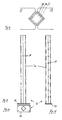
- FIG. 13 shows a view of an external sound barrier 10 with horizontally arranged Wooden planks 12 and parallel longitudinal grooves 18.
- the wooden planks 12 are according to FIGS. 9 to 12 in the support profiles 30 of brackets 32 held on the face.
- the base plate 34 of the brackets is over concrete tubes 40 anchored on a concrete foundation 42. In the present case they are individual wooden planks 12 150 cm long and 10 cm wide, the concrete pipes are 40 80 cm long.
- the base plates 34 can also be on an existing wall or the like. are attached.
- Street level 44 runs approximately horizontally.
- the street level runs 44 with a gradient of about 7 °.
- the individual external noise barriers 10 are offset by two wooden planks 12 and arranged horizontally.
- the wooden planks 12 can also be used a slope of about 7 °.
- the end faces are practical cut at an appropriate angle.
- the slope of the wooden planks 12 brings the advantage that the longitudinal grooves 18 even with undercut lower Longitudinal grooves 18 are always free of water.
- oblique slots 18 show the lowest area of a wooden plank 12 with several in parallel Longitudinal oblique slots 18. These oblique longitudinal grooves 18 have parallel side walls 46 and extend at an angle of inclination ⁇ of about 45 °. The outlet opening of the oblique slots 18 is located below so that injected water runs off better. After a not shown Variant, the oblique slots 18 can also be undercut his.
Landscapes
- Engineering & Computer Science (AREA)
- Architecture (AREA)
- Civil Engineering (AREA)
- Structural Engineering (AREA)
- Life Sciences & Earth Sciences (AREA)
- Sustainable Development (AREA)
- Devices Affording Protection Of Roads Or Walls For Sound Insulation (AREA)
- Finishing Walls (AREA)
Abstract
Description
- Von der zu absorbierenden Schallintensität, je mehr Schall zu absorbieren ist, desto näher liegen die Nuten beisammen,
- Von der Querschnittgeometrie der Längsnuten, je grösser der Querschnitt der Längsnuten ist, desto weiter können sie auseinandergerückt werden.
- Von der erforderlichen mechanischen Stabilität. Bei hohen Anforderungen liegen die Nuten weiter auseinander, bei mechanisch wenig festem Holz ebenfalls.
- Fig. 1 einen Querschnitt durch zwei längsseitig aneinander liegende Holzbohlen mit symmetrischer, tulpenförmiger Längsnut,
- Fig. 2 eine Längsnut gemäss Fig. 1 mit unterschiedlicher, gestrichelt dargestellter Schallführung,
- Fig. 3 zwei längsseitig aneinander liegende Holzbohlen mit asymmetrischer Längsnut,
- Fig. 4 eine Variante gemäss Fig. 3 mit unterschiedlicher Schallführung,
- Fig. 5 einen Querschnitt durch eine im wesentlichen zylindermantelförmige Längsnut,
- Fig. 6 eine verkürzte Variante von Fig. 5,
- Fig. 7 eine weitere Variante gemäss Fig. 5,
- Fig. 8 eine letzte Variante gemäss Fig. 5,
- Fig. 9 eine Draufsicht auf eine stirnseitige Verbindung von Holzbohlen,
- Fig. 10 eine Draufsicht auf eine Konsole gemäss Fig. 9,
- Fig. 11 eine Ansicht von Fig. 10,
- Fig. 12 eine Seitenansicht von Fig. 11,
- Fig. 13 eine Ansicht einer Aussenschallschutzwand einer ebenen Strasse,
- Fig. 14 eine Seitenansicht einer Aussenschallschutzwand einer Strasse mit Gefälle, und
- Fig. 15 einen Querschnitt durch eine Holzbohle mit Schrägschlitzen.
Claims (10)
- Aussenschallschutzwand (10) an Verkehrswegen, Baustellen und lärmigen Fabrikations-, Betriebs-, Sport- oder Unterhaltungsstätten im Freien,
dadurch gekennzeichnet, dass
die Schallschutzwand (10) aus massiven Holzbohlen (12) mit längslaufenden, wenigstens einseitig hinterschnittenen und/oder als Schrägschlitze ausgebildeten Längsnuten (18), welche in Richtung der Lärmquelle/n (Q) offen sind, besteht. - Schutzwand (10) nach Anspruch 1, dadurch gekennzeichnet, dass die Tiefe (t) der Längsnuten (18) 30 bis 70% der Dicke (d) von vorzugsweise 5 bis 15 cm der Holzbohlen (12) beträgt.
- Schutzwand (10) nach Anspruch 1 oder 2, dadurch gekennzeichnet, dass die Längsnuten (18) entlang der aufeinander liegenden Seitenflächen von zwei Holzbohlen (12) oder in deren Innern (A,B) verlaufen.
- Schutzwand (10) nach einem der Ansprüche 1 bis 3, dadurch gekennzeichnet, dass die symmetrischen Längsnuten (18) hinter dem Eingangsschlitz (20) querschnittlich im wesentlichen kreisförmig, halbkreisförmig, elliptisch, baumförmig, tannenförmig oder abgestuft ausgebildet sind.
- Schutzwand (10) nach einem der Ansprüche 1 bis 3, dadurch gekennzeichnet, dass die Längsnuten (18) bezüglich ihrer Längsebene querschnittlich asymmetrisch ausgebildet sind.
- Schutzwand (10) nach einem der Ansprüche 1 bis 3, dadurch gekennzeichnet, dass die als Schrägschlitze ausgebildeten Längsnuten (18) einen Neigungswinkel (β) von 30 bis 60°, insbesondere etwa 45°, und vorzugsweise parallel verlaufende Seitenwände (46) haben.
- Schutzwand (10) nach einem der Ansprüche 1 bis 6, dadurch gekennzeichnet, dass die Längsnuten (18) wenigstens teilweise ausgeschäumt sind, vorzugsweise mit offenporigem Kunststoffschaum (19).
- Schutzwand (10) nach einem der Ansprüche 1 bis 7, dadurch gekennzeichnet, dass die Bereiche zwischen den Längsnuten (18) der Holzbohlen (12) in rohem Sägezustand vorliegen.
- Schutzbereich (10) nach einem der Ansprüche 1 bis 8, dadurch gekennzeichnet, dass die Bereiche zwischen den Längsnuten (18) der Holzbohlen (12) mit einer schallabsorbierenden Schicht (26) abgedeckt sind, vorzugsweise mit einem Faservlies.
- Schutzwand (10) nach einem der Ansprüche 1 bis 9, dadurch gekennzeichnet, dass die Holzbohlen (12) horizontal oder mit geringer Neigung gegenüber der Horizontalen angeordnet und stirnseitig durch Stützprofile (30) gehaltert sind.
Applications Claiming Priority (2)
| Application Number | Priority Date | Filing Date | Title |
|---|---|---|---|
| CH20000815 | 2000-04-26 | ||
| CH8152000A CH694373A5 (de) | 2000-04-26 | 2000-04-26 | Aussenschallschutzwand. |
Publications (2)
| Publication Number | Publication Date |
|---|---|
| EP1149952A2 true EP1149952A2 (de) | 2001-10-31 |
| EP1149952A3 EP1149952A3 (de) | 2003-03-26 |
Family
ID=4538886
Family Applications (1)
| Application Number | Title | Priority Date | Filing Date |
|---|---|---|---|
| EP01810385A Withdrawn EP1149952A3 (de) | 2000-04-26 | 2001-04-20 | Aussenschallschutzwand |
Country Status (2)
| Country | Link |
|---|---|
| EP (1) | EP1149952A3 (de) |
| CH (1) | CH694373A5 (de) |
Cited By (2)
| Publication number | Priority date | Publication date | Assignee | Title |
|---|---|---|---|---|
| DE102006003304A1 (de) * | 2006-01-23 | 2007-03-22 | Infineon Technologies Ag | Leistungshalbleiterbauteil und Verfahren zu seiner Herstellung |
| DE102010009987A1 (de) * | 2010-03-02 | 2011-09-08 | Bettina Köhne | Schallschutzschirm |
Family Cites Families (2)
| Publication number | Priority date | Publication date | Assignee | Title |
|---|---|---|---|---|
| DE3322189A1 (de) * | 1983-06-21 | 1985-01-10 | Sf-Vollverbundstein-Kooperation Gmbh, 2820 Bremen | Schallabsorbierender formstein sowie schallschutzwand aus formsteinen |
| CH688097A5 (de) * | 1994-08-31 | 1997-05-15 | Cycrollo Ag | Bausatz zur Erstellung einer Schallschutzwand. |
-
2000
- 2000-04-26 CH CH8152000A patent/CH694373A5/de not_active IP Right Cessation
-
2001
- 2001-04-20 EP EP01810385A patent/EP1149952A3/de not_active Withdrawn
Cited By (2)
| Publication number | Priority date | Publication date | Assignee | Title |
|---|---|---|---|---|
| DE102006003304A1 (de) * | 2006-01-23 | 2007-03-22 | Infineon Technologies Ag | Leistungshalbleiterbauteil und Verfahren zu seiner Herstellung |
| DE102010009987A1 (de) * | 2010-03-02 | 2011-09-08 | Bettina Köhne | Schallschutzschirm |
Also Published As
| Publication number | Publication date |
|---|---|
| EP1149952A3 (de) | 2003-03-26 |
| CH694373A5 (de) | 2004-12-15 |
Similar Documents
| Publication | Publication Date | Title |
|---|---|---|
| DE2303879B2 (de) | Schallabsorbierendes Bauelement | |
| EP2163705A2 (de) | Wandverkleidung mit Füllmaterial und Funktionsschicht | |
| DE2718290A1 (de) | Bauelementsystem zur erstellung bepflanzbarer mauern | |
| EP2126218B1 (de) | Absorber mit trägerprofilen | |
| AT404147B (de) | Schallschutzwand zur dämmung von schallemissionen von verkehrsmitteln | |
| EP1149952A2 (de) | Aussenschallschutzwand | |
| EP3929169A2 (de) | Lehmelemente für lärmschutzwände und für den hochbau | |
| EP3498929B1 (de) | Hochbau-gebäudemodul und daraus hergestelltes gebäude | |
| AT512523B1 (de) | Fundamentlose Lärmschutzvorrichtung | |
| AT395990B (de) | Laermschutzwand | |
| DE4212172A1 (de) | Leichtbau-schallschutzkonstruktion | |
| EP2516747B1 (de) | Schallschutzbauteil | |
| EP1391570A2 (de) | Wandkonstruktion und Fassadenplatte | |
| AT523001B1 (de) | Lärmschutzvorrichtung | |
| EP4396412A1 (de) | Schallschutzelement aus rohrförmigen pflanzenhalmen | |
| DE3937756A1 (de) | Schallabsorbierende wand | |
| EP1842984A2 (de) | Profiiertes Deckenrand-Abschalelement für Betondecken | |
| DE19938676A1 (de) | Schallschutzwand für Verkehrswege | |
| DE69107358T2 (de) | Lärmschutzwand. | |
| AT527411B1 (de) | Schallabsorber | |
| EP2870292B1 (de) | Gleiskörper-lärmschutzwandbauteil | |
| DE3919280A1 (de) | Schallschutzwand | |
| DE19739606A1 (de) | Bauteil, Baugruppe, Bauteilsatz oder Bauerk für Schallschutz- und/oder Stützkonstruktionen | |
| AT508153B1 (de) | Lärmschutzelement | |
| DE2354047B2 (de) | Lärmschutzwand |
Legal Events
| Date | Code | Title | Description |
|---|---|---|---|
| PUAI | Public reference made under article 153(3) epc to a published international application that has entered the european phase |
Free format text: ORIGINAL CODE: 0009012 |
|
| AK | Designated contracting states |
Kind code of ref document: A2 Designated state(s): AT BE CH CY DE DK ES FI FR GB GR IE IT LI LU MC NL PT SE TR |
|
| AX | Request for extension of the european patent |
Free format text: AL;LT;LV;MK;RO;SI |
|
| RAP1 | Party data changed (applicant data changed or rights of an application transferred) |
Owner name: HOFZAUN GMBH |
|
| RIN1 | Information on inventor provided before grant (corrected) |
Inventor name: FLUECK, ULRICH |
|
| PUAL | Search report despatched |
Free format text: ORIGINAL CODE: 0009013 |
|
| AK | Designated contracting states |
Kind code of ref document: A3 Designated state(s): AT BE CH CY DE DK ES FI FR GB GR IE IT LI LU MC NL PT SE TR Designated state(s): AT BE CH CY DE DK ES FI FR GB GR IE IT LI LU MC NL PT SE TR |
|
| AX | Request for extension of the european patent |
Extension state: AL LT LV MK RO SI |
|
| 17P | Request for examination filed |
Effective date: 20030307 |
|
| AKX | Designation fees paid |
Designated state(s): AT BE CH CY DE DK ES FI FR GB GR IE IT LI LU MC NL PT SE TR |
|
| GRAP | Despatch of communication of intention to grant a patent |
Free format text: ORIGINAL CODE: EPIDOSNIGR1 |
|
| GRAJ | Information related to disapproval of communication of intention to grant by the applicant or resumption of examination proceedings by the epo deleted |
Free format text: ORIGINAL CODE: EPIDOSDIGR1 |
|
| GRAP | Despatch of communication of intention to grant a patent |
Free format text: ORIGINAL CODE: EPIDOSNIGR1 |
|
| STAA | Information on the status of an ep patent application or granted ep patent |
Free format text: STATUS: THE APPLICATION IS DEEMED TO BE WITHDRAWN |
|
| 18D | Application deemed to be withdrawn |
Effective date: 20090324 |