EP1150060A2 - Scheinwerfersystem für Fahrzeuge - Google Patents
Scheinwerfersystem für Fahrzeuge Download PDFInfo
- Publication number
- EP1150060A2 EP1150060A2 EP01110237A EP01110237A EP1150060A2 EP 1150060 A2 EP1150060 A2 EP 1150060A2 EP 01110237 A EP01110237 A EP 01110237A EP 01110237 A EP01110237 A EP 01110237A EP 1150060 A2 EP1150060 A2 EP 1150060A2
- Authority
- EP
- European Patent Office
- Prior art keywords
- lamp
- headlamp system
- vehicular headlamp
- reflector
- chamber
- Prior art date
- Legal status (The legal status is an assumption and is not a legal conclusion. Google has not performed a legal analysis and makes no representation as to the accuracy of the status listed.)
- Granted
Links
- 230000003287 optical effect Effects 0.000 claims description 23
- 241000282326 Felis catus Species 0.000 description 4
- 230000003247 decreasing effect Effects 0.000 description 3
- 230000004308 accommodation Effects 0.000 description 2
- 230000000875 corresponding effect Effects 0.000 description 2
- 230000010354 integration Effects 0.000 description 2
- 230000006978 adaptation Effects 0.000 description 1
- 230000004907 flux Effects 0.000 description 1
- 238000005286 illumination Methods 0.000 description 1
- 230000037431 insertion Effects 0.000 description 1
- 238000003780 insertion Methods 0.000 description 1
- 238000009434 installation Methods 0.000 description 1
- 230000002093 peripheral effect Effects 0.000 description 1
Images


Classifications
-
- B—PERFORMING OPERATIONS; TRANSPORTING
- B60—VEHICLES IN GENERAL
- B60Q—ARRANGEMENT OF SIGNALLING OR LIGHTING DEVICES, THE MOUNTING OR SUPPORTING THEREOF OR CIRCUITS THEREFOR, FOR VEHICLES IN GENERAL
- B60Q1/00—Arrangement of optical signalling or lighting devices, the mounting or supporting thereof or circuits therefor
- B60Q1/0029—Spatial arrangement
- B60Q1/0041—Spatial arrangement of several lamps in relation to each other
- B60Q1/0052—Spatial arrangement of several lamps in relation to each other concentric
-
- B—PERFORMING OPERATIONS; TRANSPORTING
- B60—VEHICLES IN GENERAL
- B60Q—ARRANGEMENT OF SIGNALLING OR LIGHTING DEVICES, THE MOUNTING OR SUPPORTING THEREOF OR CIRCUITS THEREFOR, FOR VEHICLES IN GENERAL
- B60Q1/00—Arrangement of optical signalling or lighting devices, the mounting or supporting thereof or circuits therefor
- B60Q1/0029—Spatial arrangement
- B60Q1/0041—Spatial arrangement of several lamps in relation to each other
- B60Q1/0058—Stacked, i.e. one lamp located behind the other in the optical axis direction
-
- F—MECHANICAL ENGINEERING; LIGHTING; HEATING; WEAPONS; BLASTING
- F21—LIGHTING
- F21S—NON-PORTABLE LIGHTING DEVICES; SYSTEMS THEREOF; VEHICLE LIGHTING DEVICES SPECIALLY ADAPTED FOR VEHICLE EXTERIORS
- F21S41/00—Illuminating devices specially adapted for vehicle exteriors, e.g. headlamps
-
- F—MECHANICAL ENGINEERING; LIGHTING; HEATING; WEAPONS; BLASTING
- F21—LIGHTING
- F21S—NON-PORTABLE LIGHTING DEVICES; SYSTEMS THEREOF; VEHICLE LIGHTING DEVICES SPECIALLY ADAPTED FOR VEHICLE EXTERIORS
- F21S41/00—Illuminating devices specially adapted for vehicle exteriors, e.g. headlamps
- F21S41/10—Illuminating devices specially adapted for vehicle exteriors, e.g. headlamps characterised by the light source
- F21S41/14—Illuminating devices specially adapted for vehicle exteriors, e.g. headlamps characterised by the light source characterised by the type of light source
- F21S41/17—Discharge light sources
- F21S41/172—High-intensity discharge light sources
-
- F—MECHANICAL ENGINEERING; LIGHTING; HEATING; WEAPONS; BLASTING
- F21—LIGHTING
- F21S—NON-PORTABLE LIGHTING DEVICES; SYSTEMS THEREOF; VEHICLE LIGHTING DEVICES SPECIALLY ADAPTED FOR VEHICLE EXTERIORS
- F21S41/00—Illuminating devices specially adapted for vehicle exteriors, e.g. headlamps
- F21S41/20—Illuminating devices specially adapted for vehicle exteriors, e.g. headlamps characterised by refractors, transparent cover plates, light guides or filters
- F21S41/25—Projection lenses
- F21S41/255—Lenses with a front view of circular or truncated circular outline
-
- F—MECHANICAL ENGINEERING; LIGHTING; HEATING; WEAPONS; BLASTING
- F21—LIGHTING
- F21S—NON-PORTABLE LIGHTING DEVICES; SYSTEMS THEREOF; VEHICLE LIGHTING DEVICES SPECIALLY ADAPTED FOR VEHICLE EXTERIORS
- F21S41/00—Illuminating devices specially adapted for vehicle exteriors, e.g. headlamps
- F21S41/30—Illuminating devices specially adapted for vehicle exteriors, e.g. headlamps characterised by reflectors
- F21S41/32—Optical layout thereof
- F21S41/321—Optical layout thereof the reflector being a surface of revolution or a planar surface, e.g. truncated
-
- F—MECHANICAL ENGINEERING; LIGHTING; HEATING; WEAPONS; BLASTING
- F21—LIGHTING
- F21S—NON-PORTABLE LIGHTING DEVICES; SYSTEMS THEREOF; VEHICLE LIGHTING DEVICES SPECIALLY ADAPTED FOR VEHICLE EXTERIORS
- F21S41/00—Illuminating devices specially adapted for vehicle exteriors, e.g. headlamps
- F21S41/30—Illuminating devices specially adapted for vehicle exteriors, e.g. headlamps characterised by reflectors
- F21S41/32—Optical layout thereof
- F21S41/33—Multi-surface reflectors, e.g. reflectors with facets or reflectors with portions of different curvature
- F21S41/334—Multi-surface reflectors, e.g. reflectors with facets or reflectors with portions of different curvature the reflector consisting of patch like sectors
-
- F—MECHANICAL ENGINEERING; LIGHTING; HEATING; WEAPONS; BLASTING
- F21—LIGHTING
- F21S—NON-PORTABLE LIGHTING DEVICES; SYSTEMS THEREOF; VEHICLE LIGHTING DEVICES SPECIALLY ADAPTED FOR VEHICLE EXTERIORS
- F21S41/00—Illuminating devices specially adapted for vehicle exteriors, e.g. headlamps
- F21S41/40—Illuminating devices specially adapted for vehicle exteriors, e.g. headlamps characterised by screens, non-reflecting members, light-shielding members or fixed shades
- F21S41/43—Illuminating devices specially adapted for vehicle exteriors, e.g. headlamps characterised by screens, non-reflecting members, light-shielding members or fixed shades characterised by the shape thereof
- F21S41/435—Hoods or cap-shaped
-
- F—MECHANICAL ENGINEERING; LIGHTING; HEATING; WEAPONS; BLASTING
- F21—LIGHTING
- F21S—NON-PORTABLE LIGHTING DEVICES; SYSTEMS THEREOF; VEHICLE LIGHTING DEVICES SPECIALLY ADAPTED FOR VEHICLE EXTERIORS
- F21S41/00—Illuminating devices specially adapted for vehicle exteriors, e.g. headlamps
- F21S41/60—Illuminating devices specially adapted for vehicle exteriors, e.g. headlamps characterised by a variable light distribution
- F21S41/65—Illuminating devices specially adapted for vehicle exteriors, e.g. headlamps characterised by a variable light distribution by acting on light sources
- F21S41/663—Illuminating devices specially adapted for vehicle exteriors, e.g. headlamps characterised by a variable light distribution by acting on light sources by switching light sources
-
- F—MECHANICAL ENGINEERING; LIGHTING; HEATING; WEAPONS; BLASTING
- F21—LIGHTING
- F21S—NON-PORTABLE LIGHTING DEVICES; SYSTEMS THEREOF; VEHICLE LIGHTING DEVICES SPECIALLY ADAPTED FOR VEHICLE EXTERIORS
- F21S41/00—Illuminating devices specially adapted for vehicle exteriors, e.g. headlamps
- F21S41/60—Illuminating devices specially adapted for vehicle exteriors, e.g. headlamps characterised by a variable light distribution
- F21S41/68—Illuminating devices specially adapted for vehicle exteriors, e.g. headlamps characterised by a variable light distribution by acting on screens
- F21S41/683—Illuminating devices specially adapted for vehicle exteriors, e.g. headlamps characterised by a variable light distribution by acting on screens by moving screens
- F21S41/689—Flaps, i.e. screens pivoting around one of their edges
-
- F—MECHANICAL ENGINEERING; LIGHTING; HEATING; WEAPONS; BLASTING
- F21—LIGHTING
- F21V—FUNCTIONAL FEATURES OR DETAILS OF LIGHTING DEVICES OR SYSTEMS THEREOF; STRUCTURAL COMBINATIONS OF LIGHTING DEVICES WITH OTHER ARTICLES, NOT OTHERWISE PROVIDED FOR
- F21V14/00—Controlling the distribution of the light emitted by adjustment of elements
Definitions
- the present invention relates to a vehicular headlamp system.
- Each light chamber accommodates therein a high-beam forming reflecting lamp and a low-beam forming projecting lamp vehicle-transversely spaced from each other, so that they overlap each other in a transverse direction, needing a corresponding transverse dimension for their installation.
- each light chamber has two lamps different of function, and hence is multi-functionalized, the implementation is achieved at the sacrifice of a transverse allowance of the vehicle.
- the present invention is made with such point in view. It therefore is an object of the present invention to provide a vehicular headlamp system having a light chamber multi-functionalizable by accommodation of different lamps, without significant sacrifice of a transverse allowance of an associated vehicle.
- a vehicular headlamp system comprising a lamp chamber to be provided to a vehicle, and a pair of different lamps installed in the lamp chamber, overlapping each other in a longitudinal direction of the vehicle.
- the lamp chamber is allowed to have a reduced transverse size to be sufficient for accommodation of one lamp that a greater transverse dimension.
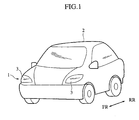
- Fig. 1 to Fig. 4 show a vehicular headlamp system 1 (Fig. 1) according to a first embodiment of the invention, which has a pair of left and right lamp chambers 3 and 3 (Fig. 1) disposed at a front of a body of a vehicle 2 (Fig. 1, Fig. 2).
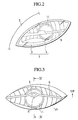
- Each lamp chamber 3 (Fig. 2) is constituted (like 103 in Fig. 8) with an enclosing housing 4 (Fig. 2) having (like 104 in Fig. 8) a relatively large cat's eye shaped front opening and a relatively small circular capped rear opening, and a transparent front cover 5 (Fig. 2) rearwardly slightly curved and fixed (like 105 in Fig. 8) to the front opening of the housing 4.
- the lamp chamber 3 accommodates therein (Fig. 4) a high-beam forming front lamp unit (as a reflecting lamp) 7 disposed (like 107 in Fig. 8) in a front half region of the lamp chamber 3, and a low-beam forming rear lamp unit (as a projecting lamp) 6 disposed (like 106 in Fig. 8) in a rear half region of the lamp chamber 3.
- the rear lamp unit (as a projecting lamp) 6 is constituted with a PES (polyellipsoid-system) concave reflector 12 (Fig. 4), an HID (high-intensity gaseous discharge) bulb 13 (Fig. 4) as a light source plugged to the reflector 12 so that its light-emitting part is located in a vicinity of a first focal point F (Fig. 4) on an optical axis Z (Fig. 4) of the reflector 12, a substantially cylindrical lens holder 14 (Fig. 4) fixed for integration at its rear end to a periphery of a front opening of the reflector 12, and an objective 11 (Fig. 2, Fig. 3, Fig. 4) as a projecting convex lens, circular in front view, having (like 111 in Fig. 8) its optical axis Z (Fig. 3, Fig. 4) aligned and common to that of the reflector 12.
- PES polyellipsoid-system concave reflector 12
- HID high
- the objective 11 has its focal point coincident with a second focal point on the optical axis Z of the reflector 12, where a top of an upwardly bent light shade 15 (Fig. 4) is located.
- the shade 15 serves as a screen to interrupt light beams lower than the top, while light beams striking the reflector 12 from the bulb 13, like arrow 'a (Fig. 4)', and reflected as direct incident beams to the objective 11, like arrow 'b (Fig. 4)', are projected through the objective 11 to constitute a low-beam light distribution pattern such that a range of projected light higher than the optical axis Z is dark relative to a lower range under the optical axis Z, that is, with a light/dark cutoff plane along the vertical axis Z.
- the front lamp unit (as a reflecting lamp) 7 is constituted with a bulb 8 (Fig. 3, Fig. 4) arranged (like 108 in Fig. 8) in a rearward oriented position for rearward emission of light at a slightly higher level than the optical axis Z of the rear lamp unit 6, a vertically angled or narrow metallic strip 9 (Fig. 2, Fig. 3, Fig. 4) as a horizontal extension (like 109 in Fig. 8) bridged between left and right ends of the front opening of the housing 4 and formed with a circular bulged central part for supporting the bulb 8, and a free-form reflector 10 (Fig. 3, Fig. 4) opened (like 110 in Fig.
- Beams of light reflected by the reflector 10 provide a high-beam light distribution pattern.
- each lamp chamber 3 allowing for each lamp chamber 3 to have a reduced transverse size, with a decreased proportion to a transverse width of the vehicle 2, and with an increased adaptation for recognition of a clearance. It is noted that the projecting lamp 6 and the reflecting lamp 7 overlap each other in a longitudinal direction of the vehicle 2 to which the optical axis Z is parallel.
- the bulb 8 is supported in the rearward oriented position on or in front of a plane connecting upper and lower front edges of the reflector 10, by the vertically narrow extension 9 bridging in front of a plane connecting upper and lower front edges of the housing 4, whereby the reflecting lamp 7 placed in front of the projecting lamp 6 is allowed to exhibit its performances, as well as the projecting lamp 6 placed behind the reflecting lamp 7.
- the location of the bulb 8 of the reflecting lamp 7 resides outside a lower half region below the optical axis Z of the objective 11, where the objective 11 has its most utilized surface area for projection of light of the projecting lamp 6, whereby the projecting lamp 6 is allowed to project an adequate quantity of light without interruption.
- peripheral components of the bulb 8 disposed in an upper half region above the optical axis Z are effectively hidden from the sight by the extension 9, whereby the headlamp system 1 is allowed to have a maintained appearance.
- the light chamber 3 has a decreased transverse width, a proportion of light from the projecting lamp 6 strikes the reflector 10 of the reflecting lamp 7, whereby the light chamber 3 has an illumination area equivalent to a sum of those of the objective 11 and the reflector 10 and greater than that of the objective 11, with an enhanced visibility as well as an improved recognition such as for a car on the opposite lane or a pedestrian standing on the road to see the vehicle 2 coming at an apparently near distance or for a crossing car or pedestrian before the vehicle 2 to be sufficiently aware of the vehicle 2 to feel an increased hesitation, resulting in an increased safety.
- the extension 9 is moderately curved to apparently constitute a chord of an upper half of a circular circumference of the objective 11, as illustrated by Fig. 2 and Fig. 3.
- Such a configuration of the extension does not always constitute a limitation to the invention, and may well be modified as follows:
- Fig. 5 shows a partially raised extension 21 in a light chamber of a vehicular headlamp system according to a second embodiment of the invention, in which the extension 21 lies substantially on a dark/light cutoff line or on a plane including an optical axis Z of an objective 11, a right transverse end of a reflector 10 centered to the optical axis Z, and a left transverse end of a cat's eye shaped front opening of the lamp chamber, while a central part of the extension 21 is raised in a relatively dark region above the optical axis Z to support a bulb 8 in position.
- Fig. 6 shows a substantially straight extension 22 in a light chamber of a vehicular headlamp system according to a third embodiment of the invention, in which the extension 22 is parallel at an upward spaced position relative to a dark/light cutoff line or a plane including an optical axis Z of an objective 11, a right transverse end of a reflector 10 centered to the optical axis Z, and a left transverse end of a cat's eye shaped front opening of the lamp chamber, so that a central part of the extension 22 is placed in a relatively dark region above the optical axis Z to support a bulb 8 in position.
- the reflector 10 is converged at the rear end on a periphery of a front end of the lens holder 14 of the projecting lamp 6, such a configuration of the reflector does not always constitute a limitation to the invention, and may well be modified as follows:
- Fig. 7 shows a reflector 23 of a reflecting lamp 7 in a lamp chamber of a vehicular headlamp system according to a fourth embodiment of the invention, in which the reflector 23 is converged at its rear end on a periphery of a housing which is formed, about a plug insertion part for a gaseous-discharge bulb 13, as a rear end part of a PES concave reflector 12 of a projecting lamp 6.
- a bulb 8 of the reflecting lamp 7 is placed in front of an objective 11 of the projecting lamp 6, in an upper region above an optical axis Z of the projecting lamp 6, like the first embodiment.
- the fourth embodiment may well be modified like the second or third embodiment.
- the front lamp unit 7 is constituted as a high-beam forming lamp having a bulb 8 therefor and the rear lamp unit 6 is constituted as a low-beam forming lamp having a fixed shade 15, such constitution is not always a limitation to the invention, and may well be modified as follows:
- Fig. 8 shows in section an entirety of a light chamber 103 in a vehicular headlamp system 101 according to a fifth embodiment of the invention, in which a front lamp unit (as a reflecting lamp) 107 constitutes a clearance lamp and a rear lamp unit (as a projecting lamp) 106 is adapted to provide a selective one of high-beam and low-beam light distribution patterns.
- a front lamp unit (as a reflecting lamp) 107 constitutes a clearance lamp
- a rear lamp unit (as a projecting lamp) 106 is adapted to provide a selective one of high-beam and low-beam light distribution patterns.
- the lamp chamber 103 is constituted with an enclosing housing 104 having a relatively large cat's eye shaped front opening and a relatively small circular capped rear opening, and a transparent front cover 105 rearwardly slightly curved and fixed to the front opening of the housing 4.
- the lamp chamber 103 accommodates therein a vehicle-clearance defining front lamp unit (as the reflecting lamp) 107 disposed in a front half region of the lamp chamber 103, and a high/low-beam selectively forming rear lamp unit (as the projecting lamp) 106 disposed in a rear half region of the lamp chamber 103.
- the rear lamp unit (as the projecting lamp) 106 is constituted with a PES concave reflector 112, an HID bulb 113 as a light source plugged to a circular receptacle part 112a of the reflector 112 so that its light-emitting part 113a is located in a vicinity of a first focal point A on an optical axis Z of the reflector 112, a substantially cylindrical lens holder 114 fixed for integration at its rear end to a periphery of a front opening of the reflector 12 and/or supported by a suitable member (not shown) fixed to the housing 104, an objective 111 as a projecting convex lens, circular in front view, having its optical axis Z aligned and common to that of the reflector 112, and a rotary solenoid 115 having a light shade 117 rotatable about a transversely extending pivot shaft 116.
- the objective 111 has its focal point coincident with a second focal point B on the optical axis Z of the reflector 112, where a forewardly bent top 118 of the light shade 117 is located, when it is set in a high position (solid line) for selection of a low-beam light distribution pattern (with light beam L2 inclusive) by electrical operation of the rotary solenoid 115 to rotate clockwise about the shaft 116 to a rear angular position.
- the shade 117 is set to a low position (phantom line) by manual or controlled operation of the rotary solenoid to rotate counterclockwise about the pivot shaft 116 to a front angular position.
- the front lamp unit (as the reflecting lamp) 107 is constituted with a clearance bulb 108 arranged in a rearward oriented position for rearward emission of light at a slightly higher level than the optical axis Z of the rear lamp unit 106, a vertically angled or narrow metallic strip 109 as a horizontal extension bridged between left and right ends of the front opening of the housing 104 and formed with a circular bulged central part for supporting the bulb 108, and a free-form reflector 110 opened at its front end to be loose-fit in the front opening of the housing 104 and converged at its rear end to have a circular opening fitted on a lens holding front end of the lens holder 114 of the rear lamp unit 106,
- Beams of light reflected by the reflector 110 provide an enhanced definition of a vehicle clearance, as the light chamber 103 has a decreased transverse size. It is noted that the clearance bulb 8 is located at a slightly higher level than the optical axis Z, where the density of light flux is relatively small because the receptacle part 112a of the reflector 112 is a dark part (like a hole). It will be seen that the fifth embodiment may be modified like the second, third, or fourth embodiment to achieve corresponding effects.
Landscapes
- Engineering & Computer Science (AREA)
- General Engineering & Computer Science (AREA)
- Mechanical Engineering (AREA)
- Non-Portable Lighting Devices Or Systems Thereof (AREA)
Applications Claiming Priority (4)
| Application Number | Priority Date | Filing Date | Title |
|---|---|---|---|
| JP2000124406A JP4042297B2 (ja) | 2000-04-25 | 2000-04-25 | 車両用前照灯 |
| JP2000124406 | 2000-04-25 | ||
| JP2001118533A JP2002313116A (ja) | 2001-04-17 | 2001-04-17 | 車両用前照灯 |
| JP2001118533 | 2001-04-17 |
Publications (3)
| Publication Number | Publication Date |
|---|---|
| EP1150060A2 true EP1150060A2 (de) | 2001-10-31 |
| EP1150060A3 EP1150060A3 (de) | 2002-10-16 |
| EP1150060B1 EP1150060B1 (de) | 2009-08-12 |
Family
ID=26590754
Family Applications (1)
| Application Number | Title | Priority Date | Filing Date |
|---|---|---|---|
| EP01110237A Expired - Lifetime EP1150060B1 (de) | 2000-04-25 | 2001-04-25 | Scheinwerfersystem für Fahrzeuge |
Country Status (3)
| Country | Link |
|---|---|
| US (1) | US6540387B2 (de) |
| EP (1) | EP1150060B1 (de) |
| DE (1) | DE60139525D1 (de) |
Cited By (3)
| Publication number | Priority date | Publication date | Assignee | Title |
|---|---|---|---|---|
| ES2247887A1 (es) * | 2003-10-06 | 2006-03-01 | Seat, S.A. | Modulo de señalizacion para grupos opticos de vehiculos automoviles. |
| EP1746339A1 (de) * | 2005-07-21 | 2007-01-24 | Valeo Vision | Vorrichtung zur Beleuchtung oder Signalgebung, insbesondere für Fahrzeuge |
| EP1867914A1 (de) * | 2006-06-15 | 2007-12-19 | Valeo Vision | Leuchtscheinwerfer mit doppelter Lichtquelle für Kraftfahrzeuge |
Families Citing this family (13)
| Publication number | Priority date | Publication date | Assignee | Title |
|---|---|---|---|---|
| US7813875B2 (en) * | 2002-10-10 | 2010-10-12 | Sirf Technology, Inc. | Layered host based satellite positioning solutions |
| FR2826431B1 (fr) * | 2001-06-26 | 2004-04-16 | Valeo Vision | Dispositif d'eclairage ou de signalisation pour vehicule automobile |
| US7145977B2 (en) * | 2003-07-30 | 2006-12-05 | International Business Machines Corporation | Diagnostic method and apparatus for non-destructively observing latch data |
| US7033054B2 (en) | 2003-08-13 | 2006-04-25 | Guide Corporation | Lamp assembly with peripheral auxiliary function |
| US7021804B2 (en) * | 2003-08-13 | 2006-04-04 | Guide Corporation | Lamp assembly with multi-stage reflector |
| JP4392786B2 (ja) * | 2003-11-04 | 2010-01-06 | 株式会社小糸製作所 | 車両用前照灯 |
| JP4053489B2 (ja) * | 2003-11-04 | 2008-02-27 | 株式会社小糸製作所 | 車両用前照灯 |
| US7036969B2 (en) * | 2003-12-04 | 2006-05-02 | Guide Corporation | Adverse weather headlamp system |
| JP2007216881A (ja) * | 2006-02-17 | 2007-08-30 | Koito Mfg Co Ltd | 車両用前照灯 |
| JP4970136B2 (ja) * | 2007-05-17 | 2012-07-04 | 株式会社小糸製作所 | 車両用前照灯の灯具ユニット |
| DE102012224079B4 (de) * | 2012-12-20 | 2014-08-21 | Automotive Lighting Reutlingen Gmbh | Lichtleiter mit einer bandförmigen Lichtaustrittsfläche |
| JP6461569B2 (ja) * | 2014-11-25 | 2019-01-30 | スタンレー電気株式会社 | 照明装置 |
| CN110397889B (zh) * | 2019-07-19 | 2024-03-15 | 帝宝车灯制造(合肥)有限公司 | 汽车led双光透镜前照灯 |
Citations (1)
| Publication number | Priority date | Publication date | Assignee | Title |
|---|---|---|---|---|
| JPH10199305A (ja) | 1997-01-10 | 1998-07-31 | Koito Mfg Co Ltd | 投射型ランプ |
Family Cites Families (18)
| Publication number | Priority date | Publication date | Assignee | Title |
|---|---|---|---|---|
| USRE19990E (en) * | 1936-05-26 | Combined vehicle signal | ||
| FR663429A (fr) * | 1928-02-18 | 1929-08-21 | Procédé et dispositif permettant d'obtenir d'un même phare soit un éclairage blanc intensif, soit un éclairage teinté évitant l'éblouissement provoqué par les phares d'automobiles ou autres | |
| DE1703233U (de) * | 1954-02-02 | 1955-07-21 | Westfaelische Metall Industrie | Abblendbarer kraftfahrzeugscheinwerfer. |
| FR1353038A (fr) * | 1963-01-11 | 1964-02-21 | Machal Projecteurs | Projecteur d'automobile à double faisceau utilisant deux sources lumineuses distinctes |
| DE3218702C2 (de) | 1982-05-18 | 1987-01-29 | Hella KG Hueck & Co, 4780 Lippstadt | Fahrzeugscheinwerfer |
| US4825343A (en) | 1985-12-27 | 1989-04-25 | Ichikoh Industries Limited | Projector type headlamp for vehicles |
| JPH0789442B2 (ja) | 1985-12-27 | 1995-09-27 | 市光工業株式会社 | プロジエクタ型の車輌用前照灯 |
| US4949226A (en) | 1988-06-24 | 1990-08-14 | Koito Seisakusko Co., Ltd. | Projector-type lighting device of expanded outline appearance for use as a vehicular headlamp or the like |
| GB2245697A (en) * | 1990-05-01 | 1992-01-08 | Jaguar Cars | Vehicle lamps |
| JP2610088B2 (ja) * | 1993-03-08 | 1997-05-14 | 株式会社小糸製作所 | 補助ランプ内蔵自動車用ヘッドランプ |
| US5902039A (en) * | 1996-11-14 | 1999-05-11 | Stanley Electric Co., Ltd. | Projector type headlamp |
| DE19704467B4 (de) | 1997-02-06 | 2006-07-20 | Automotive Lighting Reutlingen Gmbh | Fahrzeug-Scheinwerfer |
| DE19704426B4 (de) | 1997-02-06 | 2005-12-15 | Automotive Lighting Reutlingen Gmbh | Scheinwerfer für Fahrzeuge nach dem Projektionsprinzip |
| TW332245B (en) | 1997-10-14 | 1998-05-21 | Ind Tech Res Inst | The headlight for vehicle |
| DE19814480B4 (de) * | 1998-04-01 | 2006-07-20 | Automotive Lighting Reutlingen Gmbh | Scheinwerfer für Fahrzeuge nach dem Projektionsprinzip |
| US5997163A (en) * | 1998-06-09 | 1999-12-07 | L E Systems Inc. | Mobile laser spotlight system for law enforcement |
| JP3964089B2 (ja) * | 2000-01-12 | 2007-08-22 | 株式会社小糸製作所 | 車両用前照灯 |
| US6447151B1 (en) * | 2001-07-12 | 2002-09-10 | Russell K. Jones | Variable beam headlights |
-
2001
- 2001-04-25 EP EP01110237A patent/EP1150060B1/de not_active Expired - Lifetime
- 2001-04-25 US US09/840,964 patent/US6540387B2/en not_active Expired - Fee Related
- 2001-04-25 DE DE60139525T patent/DE60139525D1/de not_active Expired - Lifetime
Patent Citations (1)
| Publication number | Priority date | Publication date | Assignee | Title |
|---|---|---|---|---|
| JPH10199305A (ja) | 1997-01-10 | 1998-07-31 | Koito Mfg Co Ltd | 投射型ランプ |
Cited By (7)
| Publication number | Priority date | Publication date | Assignee | Title |
|---|---|---|---|---|
| ES2247887A1 (es) * | 2003-10-06 | 2006-03-01 | Seat, S.A. | Modulo de señalizacion para grupos opticos de vehiculos automoviles. |
| ES2247887B1 (es) * | 2003-10-06 | 2007-04-01 | Seat, S.A. | Modulo de señalizacion para grupos opticos de vehiculos automoviles. |
| EP1746339A1 (de) * | 2005-07-21 | 2007-01-24 | Valeo Vision | Vorrichtung zur Beleuchtung oder Signalgebung, insbesondere für Fahrzeuge |
| FR2888917A1 (fr) * | 2005-07-21 | 2007-01-26 | Valeo Vision Sa | Dispisitif d'eclairage ou de signalisation, notamment pour vehicule automobile |
| US7419287B2 (en) | 2005-07-21 | 2008-09-02 | Valeo Vision | Lighting or indicator device, in particular for motor vehicles |
| EP1867914A1 (de) * | 2006-06-15 | 2007-12-19 | Valeo Vision | Leuchtscheinwerfer mit doppelter Lichtquelle für Kraftfahrzeuge |
| FR2902497A1 (fr) * | 2006-06-15 | 2007-12-21 | Valeo Vision Sa | Projecteur d'eclairage a double source lumineuse pour vehicule automobile |
Also Published As
| Publication number | Publication date |
|---|---|
| EP1150060B1 (de) | 2009-08-12 |
| US6540387B2 (en) | 2003-04-01 |
| US20010033495A1 (en) | 2001-10-25 |
| EP1150060A3 (de) | 2002-10-16 |
| DE60139525D1 (de) | 2009-09-24 |
Similar Documents
| Publication | Publication Date | Title |
|---|---|---|
| EP1150060B1 (de) | Scheinwerfersystem für Fahrzeuge | |
| US6626565B2 (en) | Vehicle headlamp | |
| US6416210B1 (en) | Headlamp for a vehicle | |
| US6848814B2 (en) | Vehicle headlamp | |
| US20010019483A1 (en) | Vehicular headlamp | |
| JP2001035218A (ja) | 車両用前照灯 | |
| JP2003178613A (ja) | 自動車用の楕円タイプの照明装置 | |
| US6994460B2 (en) | Vehicular headlamp | |
| US6758589B2 (en) | Headlamp for vehicle | |
| JP4422005B2 (ja) | 車両用前照灯 | |
| JP2004207245A (ja) | 横方向光源を備えた自動車両用ヘッドライト | |
| JP3163569B2 (ja) | 自動車用ヘッドランプ | |
| US20020181246A1 (en) | Vehicular headlamp having improved long-distance visibility | |
| JP3163271B2 (ja) | 車輌用前照灯 | |
| JP2000100233A (ja) | 前照灯 | |
| JP2002245811A (ja) | 車両用前照灯 | |
| US20020145880A1 (en) | Lighting apparatus in a motor vehicle | |
| JP4459095B2 (ja) | 車両用ベンディングランプ | |
| JP2008135247A (ja) | 車両前照灯 | |
| JPH06251603A (ja) | 車輌用前照灯 | |
| US7144141B2 (en) | Self-aim vehicle light device | |
| JPH05334902A (ja) | 車両用プロジェクタ式ランプ | |
| KR100492865B1 (ko) | 차량용 전조등 | |
| JPS6026401Y2 (ja) | 車両用ヘツドランプ | |
| JP2000164022A (ja) | 前照灯 |
Legal Events
| Date | Code | Title | Description |
|---|---|---|---|
| PUAI | Public reference made under article 153(3) epc to a published international application that has entered the european phase |
Free format text: ORIGINAL CODE: 0009012 |
|
| 17P | Request for examination filed |
Effective date: 20010425 |
|
| AK | Designated contracting states |
Kind code of ref document: A2 Designated state(s): AT BE CH CY DE DK ES FI FR GB GR IE IT LI LU MC NL PT SE TR |
|
| AX | Request for extension of the european patent |
Free format text: AL;LT;LV;MK;RO;SI |
|
| PUAL | Search report despatched |
Free format text: ORIGINAL CODE: 0009013 |
|
| AK | Designated contracting states |
Kind code of ref document: A3 Designated state(s): AT BE CH CY DE DK ES FI FR GB GR IE IT LI LU MC NL PT SE TR |
|
| AX | Request for extension of the european patent |
Free format text: AL;LT;LV;MK;RO;SI |
|
| RIC1 | Information provided on ipc code assigned before grant |
Free format text: 7F 21S 8/10 A, 7F 21V 7/00 B, 7F 21W 101:10 Z |
|
| AKX | Designation fees paid |
Designated state(s): DE FR GB |
|
| 17Q | First examination report despatched |
Effective date: 20060907 |
|
| RIC1 | Information provided on ipc code assigned before grant |
Ipc: F21V 7/00 20060101ALI20070611BHEP Ipc: F21S 8/10 20060101AFI20070611BHEP |
|
| GRAP | Despatch of communication of intention to grant a patent |
Free format text: ORIGINAL CODE: EPIDOSNIGR1 |
|
| GRAS | Grant fee paid |
Free format text: ORIGINAL CODE: EPIDOSNIGR3 |
|
| GRAA | (expected) grant |
Free format text: ORIGINAL CODE: 0009210 |
|
| AK | Designated contracting states |
Kind code of ref document: B1 Designated state(s): DE FR GB |
|
| REG | Reference to a national code |
Ref country code: GB Ref legal event code: FG4D |
|
| REF | Corresponds to: |
Ref document number: 60139525 Country of ref document: DE Date of ref document: 20090924 Kind code of ref document: P |
|
| PLBE | No opposition filed within time limit |
Free format text: ORIGINAL CODE: 0009261 |
|
| STAA | Information on the status of an ep patent application or granted ep patent |
Free format text: STATUS: NO OPPOSITION FILED WITHIN TIME LIMIT |
|
| 26N | No opposition filed |
Effective date: 20100517 |
|
| PGFP | Annual fee paid to national office [announced via postgrant information from national office to epo] |
Ref country code: DE Payment date: 20120502 Year of fee payment: 12 |
|
| PGFP | Annual fee paid to national office [announced via postgrant information from national office to epo] |
Ref country code: FR Payment date: 20120504 Year of fee payment: 12 Ref country code: GB Payment date: 20120425 Year of fee payment: 12 |
|
| GBPC | Gb: european patent ceased through non-payment of renewal fee |
Effective date: 20130425 |
|
| PG25 | Lapsed in a contracting state [announced via postgrant information from national office to epo] |
Ref country code: GB Free format text: LAPSE BECAUSE OF NON-PAYMENT OF DUE FEES Effective date: 20130425 Ref country code: DE Free format text: LAPSE BECAUSE OF NON-PAYMENT OF DUE FEES Effective date: 20131101 |
|
| REG | Reference to a national code |
Ref country code: FR Ref legal event code: ST Effective date: 20131231 |
|
| REG | Reference to a national code |
Ref country code: DE Ref legal event code: R119 Ref document number: 60139525 Country of ref document: DE Effective date: 20131101 |
|
| PG25 | Lapsed in a contracting state [announced via postgrant information from national office to epo] |
Ref country code: FR Free format text: LAPSE BECAUSE OF NON-PAYMENT OF DUE FEES Effective date: 20130430 |