EP1150832B1 - Zwei-stationen presse für textilmaterial - Google Patents
Zwei-stationen presse für textilmaterial Download PDFInfo
- Publication number
- EP1150832B1 EP1150832B1 EP99917052A EP99917052A EP1150832B1 EP 1150832 B1 EP1150832 B1 EP 1150832B1 EP 99917052 A EP99917052 A EP 99917052A EP 99917052 A EP99917052 A EP 99917052A EP 1150832 B1 EP1150832 B1 EP 1150832B1
- Authority
- EP
- European Patent Office
- Prior art keywords
- pressing
- station
- press
- ram
- movable
- Prior art date
- Legal status (The legal status is an assumption and is not a legal conclusion. Google has not performed a legal analysis and makes no representation as to the accuracy of the status listed.)
- Expired - Lifetime
Links
- 239000000463 material Substances 0.000 title claims description 56
- 239000004753 textile Substances 0.000 title claims description 16
- 238000012546 transfer Methods 0.000 claims description 29
- 210000001520 comb Anatomy 0.000 claims description 4
- 238000013459 approach Methods 0.000 description 2
- 238000004891 communication Methods 0.000 description 2
- 230000001419 dependent effect Effects 0.000 description 1
- 238000013461 design Methods 0.000 description 1
- 230000009977 dual effect Effects 0.000 description 1
- 238000003780 insertion Methods 0.000 description 1
- 230000037431 insertion Effects 0.000 description 1
- 238000007689 inspection Methods 0.000 description 1
- 238000009434 installation Methods 0.000 description 1
- 238000012423 maintenance Methods 0.000 description 1
- 238000004519 manufacturing process Methods 0.000 description 1
- 238000007790 scraping Methods 0.000 description 1
- 238000012384 transportation and delivery Methods 0.000 description 1
Images


Classifications
-
- B—PERFORMING OPERATIONS; TRANSPORTING
- B30—PRESSES
- B30B—PRESSES IN GENERAL
- B30B9/00—Presses specially adapted for particular purposes
- B30B9/30—Presses specially adapted for particular purposes for baling; Compression boxes therefor
-
- B—PERFORMING OPERATIONS; TRANSPORTING
- B30—PRESSES
- B30B—PRESSES IN GENERAL
- B30B9/00—Presses specially adapted for particular purposes
- B30B9/30—Presses specially adapted for particular purposes for baling; Compression boxes therefor
- B30B9/3078—Presses specially adapted for particular purposes for baling; Compression boxes therefor with precompression means
-
- B—PERFORMING OPERATIONS; TRANSPORTING
- B30—PRESSES
- B30B—PRESSES IN GENERAL
- B30B9/00—Presses specially adapted for particular purposes
- B30B9/30—Presses specially adapted for particular purposes for baling; Compression boxes therefor
- B30B9/3003—Details
- B30B9/3014—Ejection means
Definitions
- the present invention relates to a press, for forming bales of textile material, according to the preable of claim 1.
- Two-station presses that is to say presses having a pre-pressing station and a final pressing and binding station
- presses having a pre-pressing station and a final pressing and binding station are known for example from Italian patents No. 1,201,292, No. 1,201,240, No. 1,214,914 and from Italian Registered Utility Model No. 207,273.
- These presses employ a carriage, which in certain cases also defines the pre-pressing volume, which transfers the material partly pressed in the pre-pressing station to the final pressing and binding station.
- This approach although efficient, has relatively high costs, particularly when the press has to be designed to suit particular user requirements.
- the pre-pressing volume of the first station may be bounded on two vertical sides by a movable vertical wall and by a plate or platen acting as the ram of the material.
- the movable wall may be hinged about a vertical axis, movable along horizontal tracks or otherwise constructed, so long as it can be retracted from the path of transfer of the material during the first and second stations.
- the pre-pressing volume is preferably bounded also on the remaining two vertical sides, the path of transfer of the partly pressed material from the first station to the second station may be bounded only above and below by the abovementioned containment walls, and be laterally open for some or all of its length.
- this allows the insertion of binding strap guide channels of the binding machine which is normally situated in the second final pressing station.
- the pre-pressing volume of the first station there may be, as is known per se, a zone into which the textile material coming from a so-called condenser is loaded.
- the loading zone is situated vertically above the pre-pressing volume and is separable from it by means of, for example, a system of combs that allows a pre-pressing surface to push the material out of the loading zone into the pre-pressing volume several times while keeping the pre-pressed material inside the pre-pressing volume.
- said ram that transfers the material from the first station to the second is linked to a movable horizontal panel that is interposed between the loading zone and the pre-pressing volume during the transfer of the pre-pressed material from the first station to the second. Consequently while the ram is pushing the pre-pressed material along the transfer path, it is possible to begin feeding the textile material from the condenser into the loading zone above the pre-pressing volume for the next pressing cycle. This material is temporarily held above the movable horizontal panel which is then retracted, when the ram is returned to the rest position.
- the press which has the general reference 1, comprises a first pre-pressing station 3 and a second pressing and binding station 5.
- a so-called condenser 7 which feeds in the textile material to be packaged in bales.
- the condenser 7 feeds the textile material into a loader 9, from which a cylinder-and-piston system 11 with a plate 13 having reciprocating movement indicated by the double arrow f13 discharges the textile material into a loading zone 15 situated above a pre-pressing volume 17.
- the loading zone 15 and the pre-pressing volume 17 have an associated pre-pressing plate 19 actuated by a cylinder-and-piston actuator of e.g.
- the pre-pressing volume and the loading zone 15 situated above the latter are basically rectangular in plan view, although this is not essential, as the shape of the pre-pressing volume may be different, e.g. cylindrical.
- the pre-pressing volume 17 is bounded by two fixed vertical walls 23 (Fig. 1) approximately parallel to the plane of Fig. 2, as well as by a platen 25 forming part of a ram 27 having the function specified later, and by a vertical wall 29 parallel to the platen 25 and capable of moving, specifically of pivoting about a vertical axis 29A (see Fig. 1).
- a horizontal transfer path 31 bounded above by a first containment wall 33 and below by a second containment wall 35 parallel to the wall 33.
- the transfer path 31 is, in the example illustrated, open.
- the pivoting movement of the movable wall 29 enables the pre-pressing space 17 to be placed in communication, when the wall 29 is in the position shown in Fig. 1, with the transfer path 31 leading to the final pressing station 5.
- the latter comprises a first upper pressing plate 37 actuated by a cylinder-and-piston actuator 39, and a second lower pressing plate 41 that can be moved vertically by a cylinder-and-piston actuator 43 housed in a space prepared below the plane of the floor.
- the platen 25 of the ram 27 is movable in the directions of the double arrow f27, and this movement is controlled by a horizontally extending cylinder-and-piston actuator 45 located in an extension of the transfer path 31 to the left (in Fig. 2) of the pre-pressing space 17.
- a horizontal panel 47 Connected to the platen 25 is a horizontal panel 47 that traverses in the directions of the double arrow f27 together with the platen 25 under the actuation of the actuator 45 for the purposes indicated later.
- pre-pressing space 17 and the upper containment wall 33 are two comb systems 49 that can traverse horizontally, or pivot about horizontal axes in order to hold the pre-pressed material in the pre-pressing space 17 when the pre-pressing plate 19 is raised, thus preventing the pre-pressed textile material from re-expanding in the loading zone 15.
- a binding machine 51 of a type known per se, having a series of guide channels, marked 53, for the binding straps.
- a single binding machine 51, 53 can serve more than one press and for this purpose it is movable on horizontal tracks 55 (see Fig. 1), while the channels 53 are movable along corresponding horizontal tracks 57.
- a carriage 61 with a collecting device 63 that collects and removes the pressed and bound bales from the final pressing station 5.
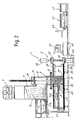
- Fig. 2 the textile material is pre-pressed in the pre-pressing space 17, while the pressing station 5 is inactive and awaits the arrival of the pre-pressed material.
- Pre-pressing is carried out by loading one or more deliveries of loose material into the loading volume 15 and then pushing this material by means of the pre-pressing plate 19 into the pre-pressing volume 17, which is bounded by the two walls parallel to the plane of Fig. 2, by the platen 25 and by the vertical movable wall 29 opposite the platen 25.
- the pre-pressing plate 19 When the pre-pressing plate 19 rises, the pre-pressed material is held in place by the combs 49, the pre-pressing plate 19 being able as it rises to pass above the combs 49 as there are corresponding slots formed in it, as known in the prior art.
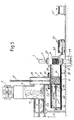
- the pre-pressing plate 19 returns to the raised position of Fig. 2 and the ram 27 transfers the pre-pressed material to the final pressing station 5.
- the cylinder-and-piston actuator 45 pushes the platen 25 toward the final pressing station 5, moving said platen 25 from the position of Fig. 2 to that of Fig. 3.
- the horizontal panel 47 follows the platen 25 of the ram 27 and closes off the bottom end of the loading space 15, where the device 11, 13 can recommence loading the material for the next pre-pressing action.
- the material introduced into the loading space 15 is temporarily held in place by the movable panel 47.
- the pre-pressed textile material M (Fig. 3) slides along, pushed by the ram 27, or more precisely by the latter's platen 25, between the upper 31 and lower 35 containment walls.
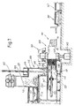
- the ram 27 can withdraw to the initial position, as shown in Fig. 4, while the pressing plates 37 and 41 can be advanced toward each other to force the material M into its final volume (Fig. 4). Simultaneously, the panel 47 having moved back out of the loading zone 15 and out of the pre-pressing volume 17, a new step of pre-pressing the material can be started in the latter. Binding takes place in the final pressing station 5 with the binding machine 51 and guide channels 53 being moved into the operating position, illustrated in Fig. 4 by the fact that these two elements are here indicated in solid lines.
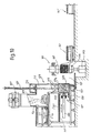
- Fig. 5 shows the removal of the pressed and bound bale and completion of pre-pressing in the pre-pressing station 3.
- the pressed and bound bales of material M are transferred by the carriage 61 to roller conveyors 67 or other suitable handling means.
- the movement in which the carriage 67 approaches the second pressing station 5 is not obstructed by the binding machine 51, which for this purpose is moved away from the tracks 69 (see in particular Fig. 1) along which the carriage 63 runs.
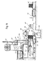
- Figs. 7 - 11 show five successive steps in the operation of a different embodiment of the press. Parts identical to or corresponding with those of Figs. 1 - 6 are given the same reference numerals increased by 100.
- the press which has the general reference 101, comprises a first pre-pressing station 103 and a second pressing and binding station 105.
- a so-called condenser 107 Connected to the pre-pressing station 103 is a so-called condenser 107 which feeds in the textile material to be packaged in bales.
- the condenser 107 feeds the textile material into a loader 109, from which a cylinder-and-piston system 111 with a plate 113 having reciprocating movement indicated by the double arrow f113 discharges the textile material into a loading zone 115 situated above a pre-pressing volume 117.
- the loading zone 115 and the pre-pressing volume 117 have an associated pre-pressing plate 119 actuated by a cylinder-and-piston actuator of e.g. hydraulic type 121.
- the pre-pressing volume 117 is bounded by two fixed vertical walls (not visible) equivalent to the walls 23 and approximately parallel to the plane of Figs. 7 - 11, as well as by a platen 125 forming part of a ram 127 and by a vertical wall 129 parallel to the platen 125 and capable of moving, specifically of pivoting about a vertical axis 129A.
- a horizontal transfer path 131 bounded above by a first wall which is formed by the vertical wall 129 when the latter assumes the raised position, as visible in Figs. 7, 8 and 11.
- a first substantial difference from the previous embodiment is therefore that a single pivoting component forms not only one of the walls of vertical closure of the pre-pressing zone, but also a first horizontal containment wall along the transfer path 131.
- This path is bounded on the underside by a second horizontal containment wall 135. This wall is movable horizontally in the same direction as the platen 125, as explained later.
- the transfer path 131 is, in the example illustrated, open.
- the pivoting movement of the movable wall 129 enables the pre-pressing space 117 to be placed in communication, when the wall 129 is in the position shown in Fig. 7, with the transfer path 131 leading to the final pressing station 105.
- the latter comprises a first fixed upper pressing plate 137 and a second lower pressing plate 141 that can be moved vertically by a cylinder-and-piston actuator 143 housed in a space prepared below the plane of floor.
- this illustrative embodiment could again have two pressing plates 137, 141 that are both movable, or else an upper plate that can move down and a fixed lower plate.
- the platen 125 of the ram 127 is movable in the directions of the double arrow f127, and this movement is controlled by a horizontally extending cylinder-and-piston actuator 145 located in an extension of the transfer path 131 to the left (in Fig. 7) of the pre-pressing space 117.
- a horizontal panel 147 Connected to the platen 125 is a horizontal panel 147 that traverses in the directions of the double arrow f127 together with the platen 125 (or at any rate in some manner coordinated with the latter) under the actuation of the actuator 145.
- pre-pressing space 117 and the upper containment wall 133 are two comb systems 149 that can pivot about horizontal axes in order to hold the pre-pressed material in the pre-pressing space 117 when the pre-pressing plate 119 is raised, thus preventing the pre-pressed textile material from re-expanding in the loading zone 115.
- a binding machine 151 similar to the binding machine 51, as well as a carriage 161 with a collecting device that collects and removes the pressed and bound bales from the final pressing station 105.
- the operation of the press illustrated in Figs. 7 - 11 is similar to the operation of the press of the previous Figs. 1 - 6 and will not therefore be described again.
- this second embodiment there is a significant difference concerning the structure of the path 131 along which the pre-pressed material is transferred to the final pressing station 105.
- the path was bounded above and below by fixed upper and lower horizontal containment walls 33 and 35, while the wall 29 acted as a retractable separator for separating the pre-pressing zone from the transfer path.
- the wall 129 assumes the dual function of a wall separating the pre-pressing zone from the transfer path, and also, in alternation, of an upper containment wall during the transfer.
- the lower horizontal containment wall 135 is no longer fixed but movable in coordination with the movement of the platen 125 of the ram 127, as visible in the sequence shown in Figs. 7 - 11.
- the wall 135 is level with the pre-pressing space 117.
- the wall 135 traverses together with the ram as far as the position of Fig. 7, and therefore in this first phase of the transfer the pre-pressed material is not scraping along the lower wall.
- the final section of the transfer movement involves sliding the material against both containment walls 129 and 135 because the latter wall remains in a fixed position (see passage from Fig. 7 to Fig. 8).
- the arrangement described immediately above makes it possible to have an unoccupied and accessible zone between the first pre-pressing station 103 and the second final pressing station 105 throughout the operational steps (or during the intervals of inactivity of the machine) except for the step in which the material is transferred from the first station to the second. This facilitates maintenance, inspection and any other operation necessary around the machine.
Landscapes
- Engineering & Computer Science (AREA)
- Mechanical Engineering (AREA)
- Auxiliary Devices For And Details Of Packaging Control (AREA)
- Basic Packing Technique (AREA)
- Treatment Of Fiber Materials (AREA)
- Reinforced Plastic Materials (AREA)
- Press Drives And Press Lines (AREA)
Claims (14)
- Presse zum Formen von Ballen aus textilem Material, umfassend eine erste Vorverpressstation und eine zweite Verpressstation, mit Umsetzungsmitteln zum Umsetzen des vorverpressten Materials von der ersten Station zur zweiten Station, wobei die Umsetzungsmittel eine obere und eine untere Eingrenzungswand umfassen, die ungefähr parallel zueinander sind und einen Umsetzungsweg zwischen der ersten Station und der zweiten station festlegen und einen Stößel, der das vorverpresste Material von der ersten Station zur zweiten Station zwischen den beiden Eingrenzungswänden drückt, dadurch gekennzeichnet, dass die Vorverpressstation eine Ladezone (15; 115) umfasst, die oberhalb eines Vorverpressvolumens (17; 117) und einer beweglichen Platte (47; 147) angeordnet ist, wobei die bewegliche Platte den Boden der Ladezone vorübergehend schließt, während der Stößel das vorverpresste Material von der ersten Station zur zweiten Station drückt.
- Presse nach Anspruch 1, dadurch gekennzeichnet, dass der Stößel das Material von der ersten Station zur zweiten umsetzt, in dem es zwischen den beiden Eingrenzungswänden geschoben wird.
- Presse nach Anspruch 1 oder 2, dadurch gekennzeichnet, dass die erste Vorverpressstation ein Vorverpressvolumen aufweist, das auf einer ersten Seite von dem Stößel und auf einer zweiten Seite, gegenüber der ersten, von einer beweglichen wand begrenzt wird, die zurückgezogen ist, während das vorverpresste Material von der ersten Station zu der zweiten umgesetzt wird.
- Presse nach Anspruch 3, dadurch gekennzeichnet, dass das vorverpressvolumen außerdem von zwei feststehenden vertikalen wänden begrenzt wird.
- Presse nach einem oder mehreren der vorangehenden Ansprüche, dadurch gekennzeichnet, dass der Stößel mit einer beweglichen horizontalen Platte verbunden ist, die zwischen einer Ladezone und dem Vorverpressvolumen eingebracht ist, während der Umsetzung des vorverpressten Materials von der ersten Vorverpressstation zur zweiten Pressstation.
- Presse nach Anspruch 5, dadurch gekennzeichnet, dass die Platte am Stößel angebracht ist.
- Presse nach einem oder mehreren der vorangehenden Ansprüche, dadurch gekennzeichnet, dass sich oberhalb des Vorverpressraumes ein System von Kämmen zum Halten des vorverpressten Materials befindet.
- Presse nach einem oder mehreren der vorangehenden Ansprüche, dadurch gekennzeichnet, dass der durch die beiden Eingrenzungswände festgelegte Weg seitlich offen ist.
- Presse nach einem oder mehreren der vorangehenden Ansprüche, dadurch gekennzeichnet, dass sie an der zweiten Pressstation eine Bindemaschine aufweist, die eine Vielzahl von Binderiemen-Führungsrillen umfasst, die während dem Binden des verpressten Materials im umsetzungsweg positioniert sind.
- Presse nach Anspruch 3, dadurch gekennzeichnet, dass die bewegliche vertikale Wand als obere Eingrenzungswand fungiert, die in die horizontale Stellung bewegt wird, während das Material von der ersten Station zur zweiten umgesetzt wird.
- Presse nach Anspruch 10, dadurch gekennzeichnet, dass die bewegliche vertikale Wand drehbar über eine horizontale Achse angebracht ist, senkrecht zur Richtung der Umsetzung des Materials zwischen der ersten und zweiten Station.
- Presse nach einem oder mehreren der vorangehenden Ansprüche, dadurch gekennzeichnet, dass die untere Eingrenzungswand beweglich ist in Richtung der Umsetzung des Materials.
- Presse nach Anspruch 12, dadurch gekennzeichnet, dass die untere Eingrenzungswand für eine Translationsbewegung geeignet ist, die mit der Translationsbewegung des Stößels abgestimmt ist.
- Presse nach Anspruch 13, dadurch gekennzeichnet, dass die Bewegung des Stößels einen weiteren Hub aufweist, der über die Bewegung der unteren Eingrenzungswand hinausgeht.
Applications Claiming Priority (3)
| Application Number | Priority Date | Filing Date | Title |
|---|---|---|---|
| IT1998FI000280A IT1305065B1 (it) | 1998-12-29 | 1998-12-29 | Pressa a doppia stazione per materiale tessile |
| ITFI980280 | 1998-12-29 | ||
| PCT/IT1999/000091 WO2000038908A1 (en) | 1998-12-29 | 1999-04-15 | Two-station press for textile material |
Publications (2)
| Publication Number | Publication Date |
|---|---|
| EP1150832A1 EP1150832A1 (de) | 2001-11-07 |
| EP1150832B1 true EP1150832B1 (de) | 2003-01-08 |
Family
ID=11352739
Family Applications (1)
| Application Number | Title | Priority Date | Filing Date |
|---|---|---|---|
| EP99917052A Expired - Lifetime EP1150832B1 (de) | 1998-12-29 | 1999-04-15 | Zwei-stationen presse für textilmaterial |
Country Status (10)
| Country | Link |
|---|---|
| US (1) | US7055424B1 (de) |
| EP (1) | EP1150832B1 (de) |
| KR (1) | KR100500629B1 (de) |
| CN (1) | CN1209237C (de) |
| AR (1) | AR015012A1 (de) |
| AU (1) | AU3532599A (de) |
| DE (1) | DE69904861T2 (de) |
| ES (1) | ES2189411T3 (de) |
| IT (1) | IT1305065B1 (de) |
| WO (1) | WO2000038908A1 (de) |
Families Citing this family (22)
| Publication number | Priority date | Publication date | Assignee | Title |
|---|---|---|---|---|
| IT1314994B1 (it) * | 2000-11-13 | 2003-01-21 | Gualchierani Textile Automatio | Pressa a doppia stazione per materiale tessile con sistema diavvolgimento del materiale pressato |
| AUPR145000A0 (en) * | 2000-11-14 | 2000-12-07 | Byrne, Laurence Michael | Compactor system |
| ITFI20010135A1 (it) * | 2001-07-13 | 2003-01-13 | Gualchierani Textile Automatio | Pressa per la formazione di balle di materiale tessile od altro,con dispositivo di rivestimento mediante un telo |
| WO2005012098A1 (en) | 2003-08-04 | 2005-02-10 | Gualchierani Textile Automation S.P.A. | Wrapping device in a press for forming bales of textile material |
| US7730832B2 (en) | 2005-04-28 | 2010-06-08 | Eastman Chemical Company | Method and apparatus for forming a bale having substantially flat upper and lower surfaces |
| AT502387B1 (de) * | 2005-05-06 | 2007-03-15 | Andritz Ag Maschf | Verfahren und vorrichtung zum pressen von zellstoffflocken zu ballen |
| DE102005042217A1 (de) * | 2005-09-05 | 2007-03-08 | Autefa Automation Gmbh | Verfahren und Vorrichtung zur Herstellung von Pressballen |
| DE202005014028U1 (de) * | 2005-09-05 | 2007-02-01 | Autefa Automation Gmbh | Vorrichtung zur Herstellung von Pressballen |
| RU2318667C1 (ru) * | 2006-06-15 | 2008-03-10 | Федеральное государственное образовательное учреждение высшего профессионального образования "Азово-Черноморская государственная агроинженерная академия" (ФГОУ ВПО АЧГАА) | Пресс для шерсти с многоскоростным электроприводом |
| CN100496960C (zh) * | 2007-05-22 | 2009-06-10 | 云南昆船设计研究院 | 一种烟草二级打包系统 |
| EP2014455B1 (de) * | 2007-07-13 | 2014-08-20 | Amadeo Farell S.A.U. | Maschine zur Formung von Ballen aus desintegriertem Material |
| GB2462417B (en) * | 2008-08-04 | 2010-08-11 | Environmental Rubber Technolog | Baling apparatus |
| US7958699B2 (en) * | 2008-12-11 | 2011-06-14 | Rethceif Enterprises, Llc | Apparatus and method for compressing and bagging a loose material |
| DE202011051610U1 (de) * | 2011-09-02 | 2012-12-06 | Autefa Solutions Germany Gmbh | Transportvorrichtung für Pressballen |
| DE202013101316U1 (de) * | 2013-03-26 | 2014-07-11 | Autefa Solutions Germany Gmbh | Verpackungseinrichtung |
| BE1021027B1 (nl) | 2013-09-24 | 2015-01-27 | Valvan Baling Systems Nv | Dubbel station balenpers inrichting. |
| DE202015102730U1 (de) * | 2015-05-27 | 2016-08-31 | Autefa Solutions Germany Gmbh | Fülleinrichtung |
| CN105216188B (zh) * | 2015-09-18 | 2018-04-24 | 鄂州市兴方磨具有限公司 | 树脂碾米砂轮半自动成型线 |
| CN105729865A (zh) * | 2016-04-18 | 2016-07-06 | 湖北天化麻业股份有限公司 | 一种梳棉输出棉网自动打包系统 |
| CN107082147B (zh) * | 2017-04-25 | 2019-06-04 | 盐城润银纺织有限公司 | 一种压爪式纱线收纳设备 |
| CN108263656B (zh) * | 2018-03-16 | 2019-11-12 | 杭州雅姿窗饰材料有限公司 | 一种液压打包机 |
| KR102569565B1 (ko) * | 2023-01-09 | 2023-08-24 | 주식회사 옳바이오 | 폐기물을 이용한 고체연료 제조장치 및 제조방법 |
Family Cites Families (10)
| Publication number | Priority date | Publication date | Assignee | Title |
|---|---|---|---|---|
| SE317917B (de) * | 1966-02-04 | 1969-11-24 | Tezuka Kosan Kk | |
| US3613556A (en) * | 1970-04-22 | 1971-10-19 | American Hoist & Derrick Co | Apparatus for horizontal baling |
| JPS5442188B2 (de) * | 1974-04-26 | 1979-12-12 | ||
| JPS5225476A (en) * | 1975-08-20 | 1977-02-25 | Sakai Jukogyo Kk | Compression treating method of material to be treated, which has react ion force and its device |
| SE7705269L (sv) * | 1977-05-05 | 1978-11-06 | Ab Sunds | Sett och anordning att genom pressning overfora voluminost material till balar |
| JPS59191596A (ja) * | 1983-04-13 | 1984-10-30 | Kensetsu Kikai Chiyousa Kk | 植物繊維性材料の圧縮成形方法及びその装置 |
| IT1198773B (it) | 1984-01-27 | 1988-12-21 | Gualchierani & C Spa | Pressa verticale per materiali sfusi,compresi cascami di fibre tessili,con fuoriuscita orizzontale del materiale pressato |
| DE3568152D1 (en) * | 1985-02-22 | 1989-03-16 | Gualchierani System | Two-stage baler |
| AU3138895A (en) * | 1994-08-05 | 1996-03-04 | Fishburne International, Inc. | Method and apparatus for producing compressed fibers |
| US5687643A (en) * | 1996-01-16 | 1997-11-18 | Felts; J. David | Method and apparatus for producing a strapped bale of compressed fibers |
-
1998
- 1998-12-29 IT IT1998FI000280A patent/IT1305065B1/it active
-
1999
- 1999-04-15 DE DE69904861T patent/DE69904861T2/de not_active Expired - Lifetime
- 1999-04-15 CN CNB998153079A patent/CN1209237C/zh not_active Expired - Fee Related
- 1999-04-15 WO PCT/IT1999/000091 patent/WO2000038908A1/en not_active Ceased
- 1999-04-15 KR KR10-2001-7008251A patent/KR100500629B1/ko not_active Expired - Fee Related
- 1999-04-15 EP EP99917052A patent/EP1150832B1/de not_active Expired - Lifetime
- 1999-04-15 ES ES99917052T patent/ES2189411T3/es not_active Expired - Lifetime
- 1999-04-15 US US09/959,056 patent/US7055424B1/en not_active Expired - Fee Related
- 1999-04-15 AU AU35325/99A patent/AU3532599A/en not_active Abandoned
- 1999-04-22 AR ARP990101867A patent/AR015012A1/es unknown
Also Published As
| Publication number | Publication date |
|---|---|
| US7055424B1 (en) | 2006-06-06 |
| ES2189411T3 (es) | 2003-07-01 |
| KR20010101324A (ko) | 2001-11-14 |
| ITFI980280A0 (it) | 1998-12-29 |
| IT1305065B1 (it) | 2001-04-10 |
| CN1209237C (zh) | 2005-07-06 |
| WO2000038908A1 (en) | 2000-07-06 |
| AR015012A1 (es) | 2001-04-11 |
| ITFI980280A1 (it) | 2000-06-29 |
| EP1150832A1 (de) | 2001-11-07 |
| KR100500629B1 (ko) | 2005-07-12 |
| DE69904861D1 (de) | 2003-02-13 |
| CN1332670A (zh) | 2002-01-23 |
| DE69904861T2 (de) | 2003-08-07 |
| AU3532599A (en) | 2000-07-31 |
Similar Documents
| Publication | Publication Date | Title |
|---|---|---|
| EP1150832B1 (de) | Zwei-stationen presse für textilmaterial | |
| SU833152A3 (ru) | Устройство дл пакетировани волокнистого материала | |
| CA1037441A (en) | Apparatus for compressing and packaging articles | |
| US5687643A (en) | Method and apparatus for producing a strapped bale of compressed fibers | |
| US4501107A (en) | Batt stacker and loader and method therefor | |
| NL193638C (nl) | Stapelinrichting. | |
| IE45479B1 (en) | Molding machine with a device for removing molded materialfrom multi-plate molds | |
| US4049260A (en) | Apparatus for feeding sheets | |
| GB1415104A (en) | Method and apparatus for packagiang baths of compressible materials | |
| US4132319A (en) | Automatic device for extracting stacks of finished hollow articles from a stacking station of a heat moulding apparatus | |
| US2831213A (en) | Feeding moist mass cakes to presses | |
| EP0198992B1 (de) | Zweistufige Ballenpresse | |
| US4936200A (en) | Preparation of individual articles from particulate material | |
| CN111976193A (zh) | 一种棉花定量打包机 | |
| EP0677376B1 (de) | Verfahren und Vorrichtung zum Formen von Ballen aus losen Materialien | |
| US3389652A (en) | Apparatus for the charging of multiplaten presses | |
| DE69113000T2 (de) | Stapelvorrichtung. | |
| US3089410A (en) | Apparatus for the pressing of fibre goods into bales | |
| CN208979893U (zh) | 一种砖的自动成型与码垛系统 | |
| US4886041A (en) | Continuous processing baking machines | |
| US4008034A (en) | Brick making machine having stripping means | |
| DE3736813A1 (de) | Fertigungsstrasse fuer scheibenbremsbelaege | |
| US626646A (en) | Press for expressing liquids from solids | |
| SU466749A1 (ru) | Выводное устройство рулонной ротационной машины | |
| EP1125717B1 (de) | Verfahren zum Stapeln von Behältern aus thermoplastischem Kunststoff und Vorrichtung zur Durchführung des Verfahrens |
Legal Events
| Date | Code | Title | Description |
|---|---|---|---|
| PUAI | Public reference made under article 153(3) epc to a published international application that has entered the european phase |
Free format text: ORIGINAL CODE: 0009012 |
|
| 17P | Request for examination filed |
Effective date: 20010718 |
|
| AK | Designated contracting states |
Kind code of ref document: A1 Designated state(s): BE CH DE ES FR GB IE LI PT |
|
| GRAG | Despatch of communication of intention to grant |
Free format text: ORIGINAL CODE: EPIDOS AGRA |
|
| 17Q | First examination report despatched |
Effective date: 20020315 |
|
| RBV | Designated contracting states (corrected) |
Designated state(s): BE CH DE ES FR GB IT LI PT |
|
| GRAG | Despatch of communication of intention to grant |
Free format text: ORIGINAL CODE: EPIDOS AGRA |
|
| GRAH | Despatch of communication of intention to grant a patent |
Free format text: ORIGINAL CODE: EPIDOS IGRA |
|
| GRAH | Despatch of communication of intention to grant a patent |
Free format text: ORIGINAL CODE: EPIDOS IGRA |
|
| GRAA | (expected) grant |
Free format text: ORIGINAL CODE: 0009210 |
|
| AK | Designated contracting states |
Kind code of ref document: B1 Designated state(s): BE CH DE ES FR GB IT LI PT |
|
| REG | Reference to a national code |
Ref country code: GB Ref legal event code: FG4D |
|
| REG | Reference to a national code |
Ref country code: CH Ref legal event code: EP |
|
| REF | Corresponds to: |
Ref document number: 69904861 Country of ref document: DE Date of ref document: 20030213 Kind code of ref document: P |
|
| REG | Reference to a national code |
Ref country code: CH Ref legal event code: NV Representative=s name: BOVARD AG PATENTANWAELTE |
|
| REG | Reference to a national code |
Ref country code: ES Ref legal event code: FG2A Ref document number: 2189411 Country of ref document: ES Kind code of ref document: T3 |
|
| ET | Fr: translation filed | ||
| PLBE | No opposition filed within time limit |
Free format text: ORIGINAL CODE: 0009261 |
|
| STAA | Information on the status of an ep patent application or granted ep patent |
Free format text: STATUS: NO OPPOSITION FILED WITHIN TIME LIMIT |
|
| 26N | No opposition filed |
Effective date: 20031009 |
|
| PGFP | Annual fee paid to national office [announced via postgrant information from national office to epo] |
Ref country code: PT Payment date: 20050330 Year of fee payment: 7 |
|
| PGFP | Annual fee paid to national office [announced via postgrant information from national office to epo] |
Ref country code: GB Payment date: 20050413 Year of fee payment: 7 |
|
| PGFP | Annual fee paid to national office [announced via postgrant information from national office to epo] |
Ref country code: FR Payment date: 20050429 Year of fee payment: 7 |
|
| PG25 | Lapsed in a contracting state [announced via postgrant information from national office to epo] |
Ref country code: GB Free format text: LAPSE BECAUSE OF NON-PAYMENT OF DUE FEES Effective date: 20060415 |
|
| PG25 | Lapsed in a contracting state [announced via postgrant information from national office to epo] |
Ref country code: PT Free format text: LAPSE BECAUSE OF NON-PAYMENT OF DUE FEES Effective date: 20061016 |
|
| GBPC | Gb: european patent ceased through non-payment of renewal fee |
Effective date: 20060415 |
|
| REG | Reference to a national code |
Ref country code: PT Ref legal event code: MM4A Free format text: LAPSE DUE TO NON-PAYMENT OF FEES Effective date: 20061016 |
|
| REG | Reference to a national code |
Ref country code: FR Ref legal event code: ST Effective date: 20061230 |
|
| PG25 | Lapsed in a contracting state [announced via postgrant information from national office to epo] |
Ref country code: FR Free format text: LAPSE BECAUSE OF NON-PAYMENT OF DUE FEES Effective date: 20060502 |
|
| REG | Reference to a national code |
Ref country code: CH Ref legal event code: PUE Owner name: VALVAN BALING SYSTEMS NV Free format text: BIELLI, TIZIANO#VIA BUOZZI, 47#59100 PRATO (IT) -TRANSFER TO- VALVAN BALING SYSTEMS NV#KROMMEBEEKSTRAAT 14#8930 MENEN (BE) |
|
| REG | Reference to a national code |
Ref country code: CH Ref legal event code: NV Representative=s name: SCHNEIDER FELDMANN AG PATENT- UND MARKENANWAELTE |
|
| REG | Reference to a national code |
Ref country code: ES Ref legal event code: PC2A Owner name: VALVAN BALING SYSTEMS NV Effective date: 20110325 |
|
| REG | Reference to a national code |
Ref country code: DE Ref legal event code: R081 Ref document number: 69904861 Country of ref document: DE Owner name: VALVAN BALING SYSTEMS NV, BE Free format text: FORMER OWNER: BIELLI, TIZIANO, PRATO, IT Effective date: 20110315 |
|
| PGFP | Annual fee paid to national office [announced via postgrant information from national office to epo] |
Ref country code: ES Payment date: 20150427 Year of fee payment: 17 Ref country code: CH Payment date: 20150420 Year of fee payment: 17 |
|
| REG | Reference to a national code |
Ref country code: CH Ref legal event code: PL |
|
| PG25 | Lapsed in a contracting state [announced via postgrant information from national office to epo] |
Ref country code: CH Free format text: LAPSE BECAUSE OF NON-PAYMENT OF DUE FEES Effective date: 20160430 Ref country code: LI Free format text: LAPSE BECAUSE OF NON-PAYMENT OF DUE FEES Effective date: 20160430 |
|
| PGFP | Annual fee paid to national office [announced via postgrant information from national office to epo] |
Ref country code: DE Payment date: 20170419 Year of fee payment: 19 |
|
| PG25 | Lapsed in a contracting state [announced via postgrant information from national office to epo] |
Ref country code: ES Free format text: LAPSE BECAUSE OF NON-PAYMENT OF DUE FEES Effective date: 20160416 |
|
| PGFP | Annual fee paid to national office [announced via postgrant information from national office to epo] |
Ref country code: IT Payment date: 20180423 Year of fee payment: 20 Ref country code: BE Payment date: 20180418 Year of fee payment: 20 |
|
| REG | Reference to a national code |
Ref country code: DE Ref legal event code: R119 Ref document number: 69904861 Country of ref document: DE |
|
| REG | Reference to a national code |
Ref country code: ES Ref legal event code: FD2A Effective date: 20181128 |
|
| PG25 | Lapsed in a contracting state [announced via postgrant information from national office to epo] |
Ref country code: DE Free format text: LAPSE BECAUSE OF NON-PAYMENT OF DUE FEES Effective date: 20181101 |
|
| REG | Reference to a national code |
Ref country code: BE Ref legal event code: MK Effective date: 20190415 |