EP1152486A1 - Antenne a lentille et reseau d'antennes a lentille - Google Patents
Antenne a lentille et reseau d'antennes a lentille Download PDFInfo
- Publication number
- EP1152486A1 EP1152486A1 EP00902133A EP00902133A EP1152486A1 EP 1152486 A1 EP1152486 A1 EP 1152486A1 EP 00902133 A EP00902133 A EP 00902133A EP 00902133 A EP00902133 A EP 00902133A EP 1152486 A1 EP1152486 A1 EP 1152486A1
- Authority
- EP
- European Patent Office
- Prior art keywords
- lens antenna
- lens
- mobile unit
- antenna
- shape
- Prior art date
- Legal status (The legal status is an assumption and is not a legal conclusion. Google has not performed a legal analysis and makes no representation as to the accuracy of the status listed.)
- Withdrawn
Links
- 239000000463 material Substances 0.000 claims description 21
- 238000004519 manufacturing process Methods 0.000 abstract description 3
- 238000013461 design Methods 0.000 description 17
- 238000000034 method Methods 0.000 description 8
- 230000006870 function Effects 0.000 description 6
- 230000005855 radiation Effects 0.000 description 4
- 239000011347 resin Substances 0.000 description 4
- 229920005989 resin Polymers 0.000 description 4
- 238000004458 analytical method Methods 0.000 description 3
- 230000014509 gene expression Effects 0.000 description 3
- 230000003287 optical effect Effects 0.000 description 3
- 238000013041 optical simulation Methods 0.000 description 3
- 238000013459 approach Methods 0.000 description 2
- 229910010293 ceramic material Inorganic materials 0.000 description 2
- 238000005520 cutting process Methods 0.000 description 2
- 230000001970 hydrokinetic effect Effects 0.000 description 2
- 238000011835 investigation Methods 0.000 description 2
- 238000000465 moulding Methods 0.000 description 2
- 239000002861 polymer material Substances 0.000 description 2
- 230000009467 reduction Effects 0.000 description 2
- 238000011160 research Methods 0.000 description 2
- 235000012093 Myrtus ugni Nutrition 0.000 description 1
- 239000004809 Teflon Substances 0.000 description 1
- 229920006362 Teflon® Polymers 0.000 description 1
- 244000061461 Tema Species 0.000 description 1
- PNEYBMLMFCGWSK-UHFFFAOYSA-N aluminium oxide Inorganic materials [O-2].[O-2].[O-2].[Al+3].[Al+3] PNEYBMLMFCGWSK-UHFFFAOYSA-N 0.000 description 1
- 230000015572 biosynthetic process Effects 0.000 description 1
- 230000008859 change Effects 0.000 description 1
- 238000004040 coloring Methods 0.000 description 1
- 239000002131 composite material Substances 0.000 description 1
- 230000007423 decrease Effects 0.000 description 1
- 238000006073 displacement reaction Methods 0.000 description 1
- 239000011521 glass Substances 0.000 description 1
- 238000007726 management method Methods 0.000 description 1
- 238000012067 mathematical method Methods 0.000 description 1
- 230000008569 process Effects 0.000 description 1
- 238000004064 recycling Methods 0.000 description 1
- 238000004088 simulation Methods 0.000 description 1
Images


Classifications
-
- H—ELECTRICITY
- H01—ELECTRIC ELEMENTS
- H01Q—ANTENNAS, i.e. RADIO AERIALS
- H01Q1/00—Details of, or arrangements associated with, antennas
- H01Q1/27—Adaptation for use in or on movable bodies
- H01Q1/32—Adaptation for use in or on road or rail vehicles
- H01Q1/325—Adaptation for use in or on road or rail vehicles characterised by the location of the antenna on the vehicle
- H01Q1/3291—Adaptation for use in or on road or rail vehicles characterised by the location of the antenna on the vehicle mounted in or on other locations inside the vehicle or vehicle body
-
- H—ELECTRICITY
- H01—ELECTRIC ELEMENTS
- H01Q—ANTENNAS, i.e. RADIO AERIALS
- H01Q1/00—Details of, or arrangements associated with, antennas
- H01Q1/27—Adaptation for use in or on movable bodies
- H01Q1/32—Adaptation for use in or on road or rail vehicles
- H01Q1/3208—Adaptation for use in or on road or rail vehicles characterised by the application wherein the antenna is used
- H01Q1/3233—Adaptation for use in or on road or rail vehicles characterised by the application wherein the antenna is used particular used as part of a sensor or in a security system, e.g. for automotive radar, navigation systems
-
- H—ELECTRICITY
- H01—ELECTRIC ELEMENTS
- H01Q—ANTENNAS, i.e. RADIO AERIALS
- H01Q15/00—Devices for reflection, refraction, diffraction or polarisation of waves radiated from an antenna, e.g. quasi-optical devices
- H01Q15/02—Refracting or diffracting devices, e.g. lens, prism
-
- H—ELECTRICITY
- H01—ELECTRIC ELEMENTS
- H01Q—ANTENNAS, i.e. RADIO AERIALS
- H01Q19/00—Combinations of primary active antenna elements and units with secondary devices, e.g. with quasi-optical devices, for giving the antenna a desired directional characteristic
- H01Q19/06—Combinations of primary active antenna elements and units with secondary devices, e.g. with quasi-optical devices, for giving the antenna a desired directional characteristic using refracting or diffracting devices, e.g. lens
- H01Q19/062—Combinations of primary active antenna elements and units with secondary devices, e.g. with quasi-optical devices, for giving the antenna a desired directional characteristic using refracting or diffracting devices, e.g. lens for focusing
Definitions
- the present invention relates to a lens antenna used with millimetric wave radar, etc. for mobile units such as vehicles.
- Radar systems for mobile units such as vehicles, e.g., cars and motorcycles are now under extensive investigations for the purpose of automatic navigators, risk managements, etc.
- radar harnessing waves in the so-called millimetric wave range enables associated systems to be easily reduced in size and weight, and so is suitable for use on mobile units.
- This radar system is generally broken down into a millimetric wave subsystem including oscillators, amplifiers, etc. and an antenna.
- Promising for this antenna is a lens antenna because it is relatively simple in structure and control of its directivity, etc. is achievable with relative ease.
- the lens antenna itself has been investigated from various point-of-views as typically set forth in JP-A's 51-100664 and 59-23483.
- a conventional lens antenna is generally made up of a body of rotation, as inoptical glass, with one surface being of geometrical shape such as plane, sphere, hyperboloid, and paraboloid, and the other surface being of quasi-optically determined shape in consideration of the performance in demand, etc.
- the antenna in the form of a body of rotation is mounted on the surface of a mobile unit, there is no option but to locate the antenna on the center axis of the mobile unit so as to reduce damage to the external design thereof as much as possible. This is because most of mobile units are horizontally symmetric.
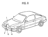
- the antenna formed on the body of rotation is also vertically symmetric, the vertically and horizontally symmetric portion of the surface of the associated mobile unit, especially an automobile is defined by a very limited portion, for instance, the leading portion of the center of a bumper, as shown at a position F in Fig. 8 as an example.
- the geometrical radiation-side surface is in no coincidence with the surface shape that forms the surface of a bumper or the like of the mobile unit such as a vehicle.
- an element of an incompatible design located on the surface of the mobile unit is a chief factor for noticeable damage to the appearance thereof.
- a conformal array antenna or the like is now under investigations, for instance, in the field of aviation equipments.
- the arrangement of a number of minute elements runs counter to cost reductions.
- the directivity performance obtained by control of a number of such elements is dynamically less than satisfactory.
- this lens antenna with a resin radome
- the formation of the resin radome using a material having improved millimetric wave properties incurs an increase in the number of additional steps, which is a factor for further cost increases, and is unsuitable for general customer-oriented, mass-produced vehicles, and so on.
- Another possible approach is to house a lens antenna within a mobile unit as shown typically at a position I in Fig. 8, which lens antenna is a body of rotation and so does not square with the external shape of the mobile unit.
- reflections and attenuations due to the exterior materials of the mobile unit make it difficult to obtain the desired performance.
- JP-A 08-139514 discloses a lens antenna integrated with a vehicle's bumper.
- a convex lens antenna is formed on the back side of the bumper by means of integral molding or a plano-convex lens antenna is located on the back side of the bumper, as typically shown at a position H in Fig. 8, so that waves passing through the lens antenna portion can also propagate through the bumper.
- USP 5,264,859 discloses a lens antenna for radar used on mobile units. As in the aforesaid publications, this publication shows nothing about the compatibility of the lens antenna with the asymmetric configuration and the surfaces of mobile units.
- An object of the present invention is to achieve a high-performance lens antenna which can be integrated with the external (surface) shape of a mobile unit with no damage to the appearance of the mobile unit, is easy to manufacture and assemble at relatively low costs as well as a lens antenna array comprising a plurality of such lens antennas.
- the lens antenna of the present invention has a non-body of rotation form. Configured in the form of a non-body of rotation, the lens antenna of the invention can be integrated with the external (surface) shape of the mobile unit with no damage to the appearance of the mobile unit, and can be easily manufactured at relatively low costs. The lens antenna of the invention can also be easily assembled while high performance is maintained intact.
- the lens antenna of the present invention it is preferable that where on the mobile unit the lens antenna is to be mounted is first determined, and the configuration of the radiation-side surface of the lens antenna is then determined in conformity to the configuration of the surface of the position of the mobile unit body where the lens antenna is to be mounted.
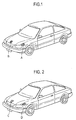
- Fig. 1 is a perspective view illustrative of a mobile unit, wherein one example of the position of the mobile unit, on which the lens antenna of the present invention is to be mounted, is shown.
- the lens antenna of the present invention is a non-body of rotation, it is acceptable that the radiation surface thereof is axially asymmetric; it is vertically/horizontally asymmetric. For this reason, the lens antenna may be mounted not only at a vertically/horizontally symmetric position on the leading end of the mobile unit but also at any given position on the leading surface of the mobile unit in such a way that it is exposed to view, as shown at a position A in Fig. 1, with no damage to the external shape of the mobile unit.
- the contour of its radiation surface is free from any area having a very small angle or radius of curvature.
- the lens antenna of the present invention may also be axially symmetric. It follows that its radiation surface, too, is axially symmetric. Accordingly, the lens antenna may be mounted not only at a vertically symmetric position on the leading end of the mobile unit but also at any given center axial position on the leading surface of the mobile unit, as shown at a position B in Fig. 1, with no damage to the external shape of the mobile unit.
- the lens antenna of the present invention may be configured such that its aperture projection surface is of either an elliptic shape or a triangular or rectangular shape containing a rounded angle.
- aperture projection surface means a projection surface obtained by cutting a bundle of waves radiating from the focus of the lens antenna and transmitting through the lens antenna along a plane vertical thereto.
- the aperture projection surface By configuring the aperture projection surface in an elliptic form or a triangular or rectangular form containing a rounded angle, it is thus possible to locate the lens antenna at a position C or D in Fig. 2 with no damage to the external design of a mobile unit.
- the junction of the surface of the mobile unit body and the surface of the lens antenna forms a continuous surface.
- the junction of the surface of the mobile unit body and the surface of the lens antenna forms a continuous surface, there is neither damage to the external design of the mobile unit nor hydrokinetic resistance even during high-speed movement.
- the direction and magnitude of inclination and curvature of the surface of the mobile unit be in coincidence with the direction and magnitude of inclination and curvature of the radiation-side surface of the lens antenna.
- coincidedence means that the direction and magnitude of inclination and curvature of the surface of the mobile unit as well as the direction and magnitude of inclination and curvature of the radiation-side surface of the lens antenna are within ⁇ 20%, and especially within ⁇ 5%.
- the lens surface shape is not always limited to a sphere that can be expressed simply by curvature; it is understood that the lens surface may be of a more complicated shape such as one given by a two-variable function of higher order or a spline surface provided that it can be expressed in terms of sequences of function data in general-purpose higher-level languages such as FORTRAN, etc, as will be described later.
- the lens antenna of the present invention as explained above, it is possible to determine where on the mobile unit the lens antenna is mounted as desired with no damage to the external design of the mobile unit, resulting in an increased degree of freedom in style and design.
- the aperture projection surface of the lens antenna may be of an elliptic shape, a triangular or rectangular shape containing a rounded angle, or a round shape as well known in the art.
- the size of the aperture projection surface must be determined on the basis of the electrical radiant properties demanded for the lens antenna.
- ⁇ the radiant half-value breadth of the lens antenna
- a the maximum length of the aperture projection surface
- ⁇ the size of the antenna aperture projection surface
- the aperture projection surface may be configured in a form other than round form in consideration of compatibility with the external design of the mobile unit. Only the requirement for this case is to satisfy the size of the aperture projection surface determined depending on the radiant half-value breadth in each direction.
- the focal position of the lens antenna is defined by a distance from the focal-side surface thereof.
- the focal position is located at a distance preferably 1/3 to 3 times, more preferably 1/2 to 2 times, and even more preferably 2/3 to 3/2 times as large as the size a of the aperture projection surface.
- the depth of an antenna system including a primary radiator may be reduced.
- the thickness of the lens antenna increase with the result that material cost increases, but also a displacement of the position for mounting the primary radiator gives rise to large performance variations.
- the lens antenna material has a large dielectric constant, there are detriments such as a radiant efficient drop.
- the lens antenna becomes thin.
- advantages such as decreases in performance variations due to the position for mounting the primary radiator and increased radiant efficiency
- there is an increased demand for the primary radiator to have sharp directivity because of an increase in the depth of the antenna system including the primary radiator.
- This often leads to another need for the provision of an additional quasi-optical system such as an auxiliary reflector, an auxiliary lens and a prism, thereby achieving a further depth reduction and giving sharp directivity to the primary radiator system.
- various materials may be used, including Teflon having improved high-frequency properties, an open-celled, porous crystalline polymer material as set forth in JP-A 59-23483, a heat-resistance, low-dielectric polymer material as set forth in JP-A 09-246052, a ceramic material or a composite material thereof.
- resin materials preference is given to resin materials because they are lightweight, and easy to mold and process.
- ceramic materials such as alumina depending on the conditions under which it is used and what purpose it is used for.
- a material having too low a specific dielectric constant makes a lens antenna too thick, resulting in weight increases, and the use of an expensive material incurs some considerable costs.
- the specific dielectric constant of a material selected for the antireflection film must be equal to the square root of the specific dielectric constant of the lens body. Therefore, if the dielectric constant ⁇ r of the lens body, for instance, is 2, then the specific dielectric constant of the surface antireflection film fit therefor is 1.41.
- materials having specific dielectric constants less than 2 are only available with difficulty. In addition, most of these materials having very low specific dielectric constants are not preferable for exposure on the surface of the mobile unit because they are fragile.
- the thickness and weight of an antenna may be reduced; however, the provision of an antireflection film is essentially required because of increased reflections. Still, the provision of the antireflection film causes the antenna to have extreme frequency properties because the frequency range, for which the antireflection film is effective, is narrow.
- the lens antenna body in such a way that the surface forming the radiating surface thereof and the focal-side surface have a quasi-optical configuration enough to function as a lens antenna in the frequency range used, a variety of quasi-optical designing methods may be used. Among others, it is preferable to use an optical simulation program.
- This optical simulation program is commercially available in the form of optical design and estimation programs, etc.
- a simulation analysis for a lens may be carried out by loading such an optical simulation program into a general-purpose personal computer (a class of personal computer with a built-in Pentium microprocessor) or a workstation, etc.
- Any given shape of the lens surface may be easily simulated on condition that the shape can be expressed in higher-level languages such as C and FORTRAN with mathematical expressions (functions), data sequences, etc. Methods for capturing the given shape in the personal computer, etc.
- the shape and thickness of the focal-side surface is determined using such a simulation program as mentioned above.
- optical simulation programs usable herein, for instance, include CODE V made by Optical Research Associates Co., Ltd., U.S.A.
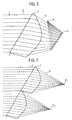
- the size of the aperture projection surface of the lens antenna is determined depending on the necessary radiant half-value breadth. In some cases, however, this size is not acceptable in view of the structure of the surface of the mobile unit on which the lens antenna is mounted or the external design of the mobile unit. Although depending on what purpose the antenna is used for, it is often required to alter the radiating direction or synthesize radiations from a plurality of antennas. In such a case, a plurality of lens antennas, each according to the present invention, are assembled in such a way as to conform to the external shape of the mobile unit. For instance, if a plurality of lens antennas 1 are integrally formed in such a way as to give proper shape and focuses F1, F2 thereto, as shown in Fig. 7, it is then possible to increase the degree of freedom in the appearance and design of a lens antenna array.
- the size of an aperture projection surface was 0.1 meter
- the radiating surface of a lens antenna was defined by a plane at an angle of 60 degrees with respect to the radiating direction
- the focal position was located 0.1 meter away from the focal surface of the lens antenna
- the dielectric constant of a lens material was 2.1.
- the lens antenna was mounted on the leading end of the hood at the center of a car body, as shown at B in Fig. 1.
- the radiation-side surface of the lens antenna was inclined with respect to the focal side upwardly from below, and the magnitude of inclination of the radiation-side surface was 60 degrees with respect to the radiating direction.
- the curvature of the radiation-side surface was infinity; the radiation-side surface was of a planar shape.
- the direction and magnitude of inclination and curvature of the radiation-side surface of the lens antenna are not necessarily in coincidence with those of the position on the surface of the mobile unit, on which the lens antenna is mounted. However, this is believed to be enough to explain the embodiment of the present invention.
- Fig. 3 is a sectional view illustrative of the lens antenna designed according to the instant example and wave propagation paths therefor. Referring to Fig. 3, as incident waves 2 enter a lens antenna 1, their paths are altered (3) to give waves 4 converging to a focus F.
- Fig. 4 is a perspective view illustrative of the structure of the lens antenna 1 of the instant example, as viewed obliquely from below on the focal side, wherein propagation paths for waves 2 and 4, the horizontal and vertical sections of the lens antenna and the shape of an aperture projection surface are shown.
- the lens antenna is of a horizontally symmetric (axially symmetric) shape.
- a similar design method may be applied while the radiation-side surface of the lens antenna is inclined from horizontal in such a way as to conform to the surface shape of the mobile unit.
- the radiation-side surface of the lens antenna is of a planar shape.
- a similar design method is applied at a curvature preset in such a way as to conform to the surface shape of the mobile unit, it is then possible to construct a lens antenna more compatible with the external shape of the mobile unit.
- the aperture projection surface of the lens antenna is of a round shape.
- the aperture projection surface is of size enough to satisfy the necessary radiant half-value breadth, it is then possible to cut the lens antenna to any given shape, thereby constructing a lens antenna more compatible with the external shape of the mobile unit.
- Fig. 5 is illustrative of the case where the upper and lower, and right and left portions of the lens antenna according to the instant example are cut off to change the shape of the aperture projection surface to a rectangular shape.
- the radiant half-value breadth in both the horizontal and vertical directions is determined by the maximum aperture size of the lens antenna in the horizontal and vertical directions; care should be taken of the fact that the radiant half-value breadth is larger than that before cutting.
- chamfering of the sections and rounding of the angles give rise to a mechanical strength increase with the result that the quality of the external shape, and especially the design of the mobile unit, is improved.
- the at least the radiation-side surface of the lens antenna according to the instant example is colored, it is then possible to construct a lens antenna more compatible with the external shape of the mobile unit.
- a high-performance lens antenna which can be integrated with the external (surface) shape of a mobile unit with no damage to the appearance of the mobile unit and is easy to manufacture and assemble at relatively low costs as well as a lens antenna array comprising a plurality of such lens antennas.
Landscapes
- Engineering & Computer Science (AREA)
- Remote Sensing (AREA)
- Computer Security & Cryptography (AREA)
- Radar, Positioning & Navigation (AREA)
- Aerials With Secondary Devices (AREA)
Applications Claiming Priority (3)
| Application Number | Priority Date | Filing Date | Title |
|---|---|---|---|
| JP3421699 | 1999-02-12 | ||
| JP3421699 | 1999-02-12 | ||
| PCT/JP2000/000667 WO2000048270A1 (fr) | 1999-02-12 | 2000-02-08 | Antenne a lentille et reseau d'antennes a lentille |
Publications (2)
| Publication Number | Publication Date |
|---|---|
| EP1152486A1 true EP1152486A1 (fr) | 2001-11-07 |
| EP1152486A4 EP1152486A4 (fr) | 2006-02-15 |
Family
ID=12407969
Family Applications (1)
| Application Number | Title | Priority Date | Filing Date |
|---|---|---|---|
| EP00902133A Withdrawn EP1152486A4 (fr) | 1999-02-12 | 2000-02-08 | Antenne a lentille et reseau d'antennes a lentille |
Country Status (4)
| Country | Link |
|---|---|
| US (1) | US6433751B1 (fr) |
| EP (1) | EP1152486A4 (fr) |
| CN (1) | CN1354900A (fr) |
| WO (1) | WO2000048270A1 (fr) |
Cited By (1)
| Publication number | Priority date | Publication date | Assignee | Title |
|---|---|---|---|---|
| WO2007009834A1 (fr) * | 2005-07-18 | 2007-01-25 | Robert Bosch Gmbh | Systeme d'antenne comprenant un radome a integrer dans une automobile |
Families Citing this family (131)
| Publication number | Priority date | Publication date | Assignee | Title |
|---|---|---|---|---|
| JP2002111359A (ja) * | 2000-09-27 | 2002-04-12 | Murata Mfg Co Ltd | アンテナ装置、通信装置およびレーダ装置 |
| DE10237790A1 (de) * | 2002-08-17 | 2004-02-26 | Robert Bosch Gmbh | Einrichtung zur Erfassung und Auswertung von Objekten im Umgebungsbereich eines Fahrzeugs |
| JP3867713B2 (ja) * | 2003-06-05 | 2007-01-10 | 住友電気工業株式会社 | 電波レンズアンテナ装置 |
| CN1327234C (zh) * | 2003-11-18 | 2007-07-18 | 电子科技大学 | 一种测量微波介质透镜天线焦斑焦距的装置 |
| US7724180B2 (en) * | 2007-05-04 | 2010-05-25 | Toyota Motor Corporation | Radar system with an active lens for adjustable field of view |
| JP4656121B2 (ja) * | 2007-10-19 | 2011-03-23 | 株式会社デンソー | レーダ装置、および保持部材 |
| JP4497190B2 (ja) * | 2007-10-19 | 2010-07-07 | 株式会社デンソー | レーダ装置、および保持部材 |
| DE102011107585A1 (de) * | 2011-07-16 | 2013-01-17 | Valeo Schalter Und Sensoren Gmbh | Optische Messvorrichtung für ein Fahrzeug, Fahrerassistenzeinrichtung mit einer derartigen Messvorrichtung sowie Fahrzeug mit einer entsprechenden Messvorrichtung |
| US9843201B1 (en) | 2012-07-06 | 2017-12-12 | Energous Corporation | Wireless power transmitter that selects antenna sets for transmitting wireless power to a receiver based on location of the receiver, and methods of use thereof |
| US10230266B1 (en) | 2014-02-06 | 2019-03-12 | Energous Corporation | Wireless power receivers that communicate status data indicating wireless power transmission effectiveness with a transmitter using a built-in communications component of a mobile device, and methods of use thereof |
| US9812890B1 (en) | 2013-07-11 | 2017-11-07 | Energous Corporation | Portable wireless charging pad |
| US10243414B1 (en) | 2014-05-07 | 2019-03-26 | Energous Corporation | Wearable device with wireless power and payload receiver |
| US9438045B1 (en) | 2013-05-10 | 2016-09-06 | Energous Corporation | Methods and systems for maximum power point transfer in receivers |
| US10211680B2 (en) | 2013-07-19 | 2019-02-19 | Energous Corporation | Method for 3 dimensional pocket-forming |
| US10312715B2 (en) | 2015-09-16 | 2019-06-04 | Energous Corporation | Systems and methods for wireless power charging |
| US10992187B2 (en) | 2012-07-06 | 2021-04-27 | Energous Corporation | System and methods of using electromagnetic waves to wirelessly deliver power to electronic devices |
| US10270261B2 (en) | 2015-09-16 | 2019-04-23 | Energous Corporation | Systems and methods of object detection in wireless power charging systems |
| US10211682B2 (en) | 2014-05-07 | 2019-02-19 | Energous Corporation | Systems and methods for controlling operation of a transmitter of a wireless power network based on user instructions received from an authenticated computing device powered or charged by a receiver of the wireless power network |
| US10291055B1 (en) | 2014-12-29 | 2019-05-14 | Energous Corporation | Systems and methods for controlling far-field wireless power transmission based on battery power levels of a receiving device |
| US10206185B2 (en) | 2013-05-10 | 2019-02-12 | Energous Corporation | System and methods for wireless power transmission to an electronic device in accordance with user-defined restrictions |
| US10381880B2 (en) | 2014-07-21 | 2019-08-13 | Energous Corporation | Integrated antenna structure arrays for wireless power transmission |
| US10008889B2 (en) | 2014-08-21 | 2018-06-26 | Energous Corporation | Method for automatically testing the operational status of a wireless power receiver in a wireless power transmission system |
| US10256657B2 (en) | 2015-12-24 | 2019-04-09 | Energous Corporation | Antenna having coaxial structure for near field wireless power charging |
| US10128693B2 (en) | 2014-07-14 | 2018-11-13 | Energous Corporation | System and method for providing health safety in a wireless power transmission system |
| US10965164B2 (en) | 2012-07-06 | 2021-03-30 | Energous Corporation | Systems and methods of wirelessly delivering power to a receiver device |
| US10141791B2 (en) | 2014-05-07 | 2018-11-27 | Energous Corporation | Systems and methods for controlling communications during wireless transmission of power using application programming interfaces |
| US11502551B2 (en) | 2012-07-06 | 2022-11-15 | Energous Corporation | Wirelessly charging multiple wireless-power receivers using different subsets of an antenna array to focus energy at different locations |
| US9825674B1 (en) | 2014-05-23 | 2017-11-21 | Energous Corporation | Enhanced transmitter that selects configurations of antenna elements for performing wireless power transmission and receiving functions |
| US10263432B1 (en) | 2013-06-25 | 2019-04-16 | Energous Corporation | Multi-mode transmitter with an antenna array for delivering wireless power and providing Wi-Fi access |
| US10186913B2 (en) | 2012-07-06 | 2019-01-22 | Energous Corporation | System and methods for pocket-forming based on constructive and destructive interferences to power one or more wireless power receivers using a wireless power transmitter including a plurality of antennas |
| US9887584B1 (en) | 2014-08-21 | 2018-02-06 | Energous Corporation | Systems and methods for a configuration web service to provide configuration of a wireless power transmitter within a wireless power transmission system |
| US10439448B2 (en) | 2014-08-21 | 2019-10-08 | Energous Corporation | Systems and methods for automatically testing the communication between wireless power transmitter and wireless power receiver |
| US10193396B1 (en) | 2014-05-07 | 2019-01-29 | Energous Corporation | Cluster management of transmitters in a wireless power transmission system |
| US10291066B1 (en) | 2014-05-07 | 2019-05-14 | Energous Corporation | Power transmission control systems and methods |
| US9787103B1 (en) | 2013-08-06 | 2017-10-10 | Energous Corporation | Systems and methods for wirelessly delivering power to electronic devices that are unable to communicate with a transmitter |
| US10223717B1 (en) | 2014-05-23 | 2019-03-05 | Energous Corporation | Systems and methods for payment-based authorization of wireless power transmission service |
| US10090699B1 (en) | 2013-11-01 | 2018-10-02 | Energous Corporation | Wireless powered house |
| US10148097B1 (en) | 2013-11-08 | 2018-12-04 | Energous Corporation | Systems and methods for using a predetermined number of communication channels of a wireless power transmitter to communicate with different wireless power receivers |
| US10063064B1 (en) | 2014-05-23 | 2018-08-28 | Energous Corporation | System and method for generating a power receiver identifier in a wireless power network |
| US10063106B2 (en) | 2014-05-23 | 2018-08-28 | Energous Corporation | System and method for a self-system analysis in a wireless power transmission network |
| US20150326070A1 (en) | 2014-05-07 | 2015-11-12 | Energous Corporation | Methods and Systems for Maximum Power Point Transfer in Receivers |
| US10063105B2 (en) | 2013-07-11 | 2018-08-28 | Energous Corporation | Proximity transmitters for wireless power charging systems |
| US9867062B1 (en) | 2014-07-21 | 2018-01-09 | Energous Corporation | System and methods for using a remote server to authorize a receiving device that has requested wireless power and to determine whether another receiving device should request wireless power in a wireless power transmission system |
| US10124754B1 (en) | 2013-07-19 | 2018-11-13 | Energous Corporation | Wireless charging and powering of electronic sensors in a vehicle |
| US10199835B2 (en) | 2015-12-29 | 2019-02-05 | Energous Corporation | Radar motion detection using stepped frequency in wireless power transmission system |
| US10224758B2 (en) | 2013-05-10 | 2019-03-05 | Energous Corporation | Wireless powering of electronic devices with selective delivery range |
| US9853458B1 (en) | 2014-05-07 | 2017-12-26 | Energous Corporation | Systems and methods for device and power receiver pairing |
| US12057715B2 (en) | 2012-07-06 | 2024-08-06 | Energous Corporation | Systems and methods of wirelessly delivering power to a wireless-power receiver device in response to a change of orientation of the wireless-power receiver device |
| US9871398B1 (en) | 2013-07-01 | 2018-01-16 | Energous Corporation | Hybrid charging method for wireless power transmission based on pocket-forming |
| US10199849B1 (en) | 2014-08-21 | 2019-02-05 | Energous Corporation | Method for automatically testing the operational status of a wireless power receiver in a wireless power transmission system |
| US10211674B1 (en) | 2013-06-12 | 2019-02-19 | Energous Corporation | Wireless charging using selected reflectors |
| US10128699B2 (en) | 2014-07-14 | 2018-11-13 | Energous Corporation | Systems and methods of providing wireless power using receiver device sensor inputs |
| US9876394B1 (en) | 2014-05-07 | 2018-01-23 | Energous Corporation | Boost-charger-boost system for enhanced power delivery |
| US10090886B1 (en) | 2014-07-14 | 2018-10-02 | Energous Corporation | System and method for enabling automatic charging schedules in a wireless power network to one or more devices |
| US10103582B2 (en) | 2012-07-06 | 2018-10-16 | Energous Corporation | Transmitters for wireless power transmission |
| US10205239B1 (en) | 2014-05-07 | 2019-02-12 | Energous Corporation | Compact PIFA antenna |
| US10038337B1 (en) | 2013-09-16 | 2018-07-31 | Energous Corporation | Wireless power supply for rescue devices |
| US10218227B2 (en) | 2014-05-07 | 2019-02-26 | Energous Corporation | Compact PIFA antenna |
| US10141768B2 (en) | 2013-06-03 | 2018-11-27 | Energous Corporation | Systems and methods for maximizing wireless power transfer efficiency by instructing a user to change a receiver device's position |
| US9859797B1 (en) | 2014-05-07 | 2018-01-02 | Energous Corporation | Synchronous rectifier design for wireless power receiver |
| US10992185B2 (en) | 2012-07-06 | 2021-04-27 | Energous Corporation | Systems and methods of using electromagnetic waves to wirelessly deliver power to game controllers |
| US9124125B2 (en) | 2013-05-10 | 2015-09-01 | Energous Corporation | Wireless power transmission with selective range |
| JP2014115155A (ja) * | 2012-12-07 | 2014-06-26 | National Univ Corp Shizuoka Univ | レンズアンテナを用いる車載用レーダ |
| US10103552B1 (en) | 2013-06-03 | 2018-10-16 | Energous Corporation | Protocols for authenticated wireless power transmission |
| US10021523B2 (en) | 2013-07-11 | 2018-07-10 | Energous Corporation | Proximity transmitters for wireless power charging systems |
| US10075017B2 (en) | 2014-02-06 | 2018-09-11 | Energous Corporation | External or internal wireless power receiver with spaced-apart antenna elements for charging or powering mobile devices using wirelessly delivered power |
| US10158257B2 (en) | 2014-05-01 | 2018-12-18 | Energous Corporation | System and methods for using sound waves to wirelessly deliver power to electronic devices |
| US10153653B1 (en) | 2014-05-07 | 2018-12-11 | Energous Corporation | Systems and methods for using application programming interfaces to control communications between a transmitter and a receiver |
| US10170917B1 (en) | 2014-05-07 | 2019-01-01 | Energous Corporation | Systems and methods for managing and controlling a wireless power network by establishing time intervals during which receivers communicate with a transmitter |
| US10153645B1 (en) | 2014-05-07 | 2018-12-11 | Energous Corporation | Systems and methods for designating a master power transmitter in a cluster of wireless power transmitters |
| US10068703B1 (en) | 2014-07-21 | 2018-09-04 | Energous Corporation | Integrated miniature PIFA with artificial magnetic conductor metamaterials |
| US10116143B1 (en) | 2014-07-21 | 2018-10-30 | Energous Corporation | Integrated antenna arrays for wireless power transmission |
| US10122415B2 (en) | 2014-12-27 | 2018-11-06 | Energous Corporation | Systems and methods for assigning a set of antennas of a wireless power transmitter to a wireless power receiver based on a location of the wireless power receiver |
| US10418716B2 (en) * | 2015-08-27 | 2019-09-17 | Commscope Technologies Llc | Lensed antennas for use in cellular and other communications systems |
| US10523033B2 (en) | 2015-09-15 | 2019-12-31 | Energous Corporation | Receiver devices configured to determine location within a transmission field |
| US12283828B2 (en) | 2015-09-15 | 2025-04-22 | Energous Corporation | Receiver devices configured to determine location within a transmission field |
| US10008875B1 (en) | 2015-09-16 | 2018-06-26 | Energous Corporation | Wireless power transmitter configured to transmit power waves to a predicted location of a moving wireless power receiver |
| US10211685B2 (en) | 2015-09-16 | 2019-02-19 | Energous Corporation | Systems and methods for real or near real time wireless communications between a wireless power transmitter and a wireless power receiver |
| US10158259B1 (en) | 2015-09-16 | 2018-12-18 | Energous Corporation | Systems and methods for identifying receivers in a transmission field by transmitting exploratory power waves towards different segments of a transmission field |
| US11710321B2 (en) | 2015-09-16 | 2023-07-25 | Energous Corporation | Systems and methods of object detection in wireless power charging systems |
| US10199850B2 (en) | 2015-09-16 | 2019-02-05 | Energous Corporation | Systems and methods for wirelessly transmitting power from a transmitter to a receiver by determining refined locations of the receiver in a segmented transmission field associated with the transmitter |
| US10778041B2 (en) | 2015-09-16 | 2020-09-15 | Energous Corporation | Systems and methods for generating power waves in a wireless power transmission system |
| US9871387B1 (en) | 2015-09-16 | 2018-01-16 | Energous Corporation | Systems and methods of object detection using one or more video cameras in wireless power charging systems |
| US10186893B2 (en) | 2015-09-16 | 2019-01-22 | Energous Corporation | Systems and methods for real time or near real time wireless communications between a wireless power transmitter and a wireless power receiver |
| US10033222B1 (en) | 2015-09-22 | 2018-07-24 | Energous Corporation | Systems and methods for determining and generating a waveform for wireless power transmission waves |
| US10135295B2 (en) | 2015-09-22 | 2018-11-20 | Energous Corporation | Systems and methods for nullifying energy levels for wireless power transmission waves |
| US10020678B1 (en) | 2015-09-22 | 2018-07-10 | Energous Corporation | Systems and methods for selecting antennas to generate and transmit power transmission waves |
| US10153660B1 (en) | 2015-09-22 | 2018-12-11 | Energous Corporation | Systems and methods for preconfiguring sensor data for wireless charging systems |
| US10027168B2 (en) | 2015-09-22 | 2018-07-17 | Energous Corporation | Systems and methods for generating and transmitting wireless power transmission waves using antennas having a spacing that is selected by the transmitter |
| US10128686B1 (en) | 2015-09-22 | 2018-11-13 | Energous Corporation | Systems and methods for identifying receiver locations using sensor technologies |
| US10050470B1 (en) | 2015-09-22 | 2018-08-14 | Energous Corporation | Wireless power transmission device having antennas oriented in three dimensions |
| US10135294B1 (en) | 2015-09-22 | 2018-11-20 | Energous Corporation | Systems and methods for preconfiguring transmission devices for power wave transmissions based on location data of one or more receivers |
| US10333332B1 (en) | 2015-10-13 | 2019-06-25 | Energous Corporation | Cross-polarized dipole antenna |
| US10734717B2 (en) | 2015-10-13 | 2020-08-04 | Energous Corporation | 3D ceramic mold antenna |
| US9853485B2 (en) | 2015-10-28 | 2017-12-26 | Energous Corporation | Antenna for wireless charging systems |
| US10063108B1 (en) | 2015-11-02 | 2018-08-28 | Energous Corporation | Stamped three-dimensional antenna |
| US10135112B1 (en) | 2015-11-02 | 2018-11-20 | Energous Corporation | 3D antenna mount |
| US10027180B1 (en) | 2015-11-02 | 2018-07-17 | Energous Corporation | 3D triple linear antenna that acts as heat sink |
| US10038332B1 (en) | 2015-12-24 | 2018-07-31 | Energous Corporation | Systems and methods of wireless power charging through multiple receiving devices |
| US10320446B2 (en) | 2015-12-24 | 2019-06-11 | Energous Corporation | Miniaturized highly-efficient designs for near-field power transfer system |
| US10277054B2 (en) | 2015-12-24 | 2019-04-30 | Energous Corporation | Near-field charging pad for wireless power charging of a receiver device that is temporarily unable to communicate |
| US10079515B2 (en) | 2016-12-12 | 2018-09-18 | Energous Corporation | Near-field RF charging pad with multi-band antenna element with adaptive loading to efficiently charge an electronic device at any position on the pad |
| US10027159B2 (en) | 2015-12-24 | 2018-07-17 | Energous Corporation | Antenna for transmitting wireless power signals |
| US11863001B2 (en) | 2015-12-24 | 2024-01-02 | Energous Corporation | Near-field antenna for wireless power transmission with antenna elements that follow meandering patterns |
| US10256677B2 (en) | 2016-12-12 | 2019-04-09 | Energous Corporation | Near-field RF charging pad with adaptive loading to efficiently charge an electronic device at any position on the pad |
| US10263476B2 (en) | 2015-12-29 | 2019-04-16 | Energous Corporation | Transmitter board allowing for modular antenna configurations in wireless power transmission systems |
| EP3242358B1 (fr) | 2016-05-06 | 2020-06-17 | Amphenol Antenna Solutions, Inc. | Antenne multifaisceau à gain élevé pour communications sans fil 5g |
| US10923954B2 (en) | 2016-11-03 | 2021-02-16 | Energous Corporation | Wireless power receiver with a synchronous rectifier |
| JP6691273B2 (ja) | 2016-12-12 | 2020-04-28 | エナージャス コーポレイション | 配送される無線電力を最大化するために近接場充電パッドのアンテナ区域を選択的に活性化する方法 |
| US10389161B2 (en) | 2017-03-15 | 2019-08-20 | Energous Corporation | Surface mount dielectric antennas for wireless power transmitters |
| US10439442B2 (en) | 2017-01-24 | 2019-10-08 | Energous Corporation | Microstrip antennas for wireless power transmitters |
| US10680319B2 (en) | 2017-01-06 | 2020-06-09 | Energous Corporation | Devices and methods for reducing mutual coupling effects in wireless power transmission systems |
| WO2018183892A1 (fr) | 2017-03-30 | 2018-10-04 | Energous Corporation | Antennes plates ayant deux fréquences de résonance ou plus destinées à être utilisées dans des systèmes de transmission de puissance sans fil |
| US10511097B2 (en) | 2017-05-12 | 2019-12-17 | Energous Corporation | Near-field antennas for accumulating energy at a near-field distance with minimal far-field gain |
| US11462949B2 (en) | 2017-05-16 | 2022-10-04 | Wireless electrical Grid LAN, WiGL Inc | Wireless charging method and system |
| US12074460B2 (en) | 2017-05-16 | 2024-08-27 | Wireless Electrical Grid Lan, Wigl Inc. | Rechargeable wireless power bank and method of using |
| US12074452B2 (en) | 2017-05-16 | 2024-08-27 | Wireless Electrical Grid Lan, Wigl Inc. | Networked wireless charging system |
| US10848853B2 (en) | 2017-06-23 | 2020-11-24 | Energous Corporation | Systems, methods, and devices for utilizing a wire of a sound-producing device as an antenna for receipt of wirelessly delivered power |
| US10587034B2 (en) * | 2017-09-29 | 2020-03-10 | Commscope Technologies Llc | Base station antennas with lenses for reducing upwardly-directed radiation |
| US10122219B1 (en) | 2017-10-10 | 2018-11-06 | Energous Corporation | Systems, methods, and devices for using a battery as a antenna for receiving wirelessly delivered power from radio frequency power waves |
| US11342798B2 (en) | 2017-10-30 | 2022-05-24 | Energous Corporation | Systems and methods for managing coexistence of wireless-power signals and data signals operating in a same frequency band |
| KR102372983B1 (ko) * | 2017-12-05 | 2022-03-11 | 현대자동차주식회사 | 안테나 장치 및 차량 |
| US10615647B2 (en) | 2018-02-02 | 2020-04-07 | Energous Corporation | Systems and methods for detecting wireless power receivers and other objects at a near-field charging pad |
| US11159057B2 (en) | 2018-03-14 | 2021-10-26 | Energous Corporation | Loop antennas with selectively-activated feeds to control propagation patterns of wireless power signals |
| US11515732B2 (en) | 2018-06-25 | 2022-11-29 | Energous Corporation | Power wave transmission techniques to focus wirelessly delivered power at a receiving device |
| US11437735B2 (en) | 2018-11-14 | 2022-09-06 | Energous Corporation | Systems for receiving electromagnetic energy using antennas that are minimally affected by the presence of the human body |
| KR20210117283A (ko) | 2019-01-28 | 2021-09-28 | 에너저스 코포레이션 | 무선 전력 전송을 위한 소형 안테나에 대한 시스템들 및 방법들 |
| JP2022519749A (ja) | 2019-02-06 | 2022-03-24 | エナージャス コーポレイション | アンテナアレイ内の個々のアンテナに使用するための最適位相を推定するシステム及び方法 |
| CN111916911B (zh) * | 2019-05-10 | 2022-02-08 | 北京小米移动软件有限公司 | 终端 |
| CN110212310B (zh) * | 2019-06-19 | 2021-07-16 | 西安电子科技大学 | 加载qcto透镜的共形相控阵天线 |
| JP2022139372A (ja) * | 2021-03-11 | 2022-09-26 | パナソニックIpマネジメント株式会社 | レーダ装置 |
Family Cites Families (18)
| Publication number | Priority date | Publication date | Assignee | Title |
|---|---|---|---|---|
| US3146451A (en) * | 1956-10-29 | 1964-08-25 | Lab For Electronics Inc | Dielectric lens giving perfect focal points at selected distance off-axis |
| US3255454A (en) * | 1964-02-06 | 1966-06-07 | Carlton H Walter | Surface wave luneberg lens antenna system |
| JPS51100664A (ja) | 1975-03-03 | 1976-09-06 | Nippon Telegraph & Telephone | Kyokumenshuseigatajudentairenzuantena |
| US4224626A (en) * | 1978-10-10 | 1980-09-23 | The United States Of America As Represented By The Secretary Of The Navy | Ellipticized lens providing balanced astigmatism |
| JPS56141603A (en) * | 1980-04-04 | 1981-11-05 | Nec Corp | Plural horn type antenna |
| JPS5923483A (ja) | 1982-07-29 | 1984-02-06 | 日本電気株式会社 | 電気接触ピン |
| US4591864A (en) * | 1983-06-13 | 1986-05-27 | The United States Of America As Represented By The Secretary Of The Navy | Frequency independent twisted wave front constant beamwidth lens antenna |
| JPS59231903A (ja) * | 1983-06-14 | 1984-12-26 | Nec Corp | 電波レンズアンテナ |
| US4847628A (en) | 1988-07-07 | 1989-07-11 | The United States Of America As Represented By The Secretary Of The Navy | Frequency independent constant beamwidth directional lens antenna for very wideband and multi-channel electromagnetic communications |
| JPH0479403A (ja) * | 1990-07-18 | 1992-03-12 | Murata Mfg Co Ltd | レンズアンテナ形成方法 |
| US5264859A (en) | 1991-11-05 | 1993-11-23 | Hughes Aircraft Company | Electronically scanned antenna for collision avoidance radar |
| JPH06152228A (ja) * | 1992-11-12 | 1994-05-31 | Bridgestone Corp | リフレクターの製造方法 |
| JPH0799407A (ja) * | 1993-09-27 | 1995-04-11 | Hitachi Denshi Ltd | マイクロ波中継用誘電体レンズ及びそれを備えた無線中継装置 |
| US6025796A (en) * | 1996-12-09 | 2000-02-15 | Crosby, Ii; Robert G. | Radar detector for pre-impact airbag triggering |
| WO1998035403A1 (fr) * | 1997-02-06 | 1998-08-13 | Robert Bosch Gmbh | Ensemble antenne hyperfrequence pour systeme radar de vehicule a moteur |
| JP3786497B2 (ja) * | 1997-06-13 | 2006-06-14 | 富士通株式会社 | アンテナ素子を内蔵する半導体モジュール |
| JP3650952B2 (ja) * | 1998-06-29 | 2005-05-25 | 株式会社村田製作所 | 誘電体レンズおよびそれを用いた誘電体レンズアンテナおよびそれを用いた無線装置 |
| JP3650953B2 (ja) * | 1998-06-29 | 2005-05-25 | 株式会社村田製作所 | 誘電体レンズアンテナおよびそれを用いた無線装置 |
-
2000
- 2000-02-08 EP EP00902133A patent/EP1152486A4/fr not_active Withdrawn
- 2000-02-08 CN CN00803676.4A patent/CN1354900A/zh active Pending
- 2000-02-08 WO PCT/JP2000/000667 patent/WO2000048270A1/fr not_active Ceased
-
2001
- 2001-08-13 US US09/927,637 patent/US6433751B1/en not_active Expired - Fee Related
Cited By (1)
| Publication number | Priority date | Publication date | Assignee | Title |
|---|---|---|---|---|
| WO2007009834A1 (fr) * | 2005-07-18 | 2007-01-25 | Robert Bosch Gmbh | Systeme d'antenne comprenant un radome a integrer dans une automobile |
Also Published As
| Publication number | Publication date |
|---|---|
| US6433751B1 (en) | 2002-08-13 |
| EP1152486A4 (fr) | 2006-02-15 |
| WO2000048270A1 (fr) | 2000-08-17 |
| CN1354900A (zh) | 2002-06-19 |
| US20020024471A1 (en) | 2002-02-28 |
Similar Documents
| Publication | Publication Date | Title |
|---|---|---|
| US6433751B1 (en) | Lens antenna and lens antenna array | |
| US5198827A (en) | Dual reflector scanning antenna system | |
| EP0789421B1 (fr) | Antenne de radar légère et durable à lentille | |
| CN1856907B (zh) | 电介透镜、电介透镜器件、电介透镜的设计方法、电介透镜的制造方法和收发装置 | |
| EP0593903B1 (fr) | Réflecteurs à forme de surface identique en arrangement semi-tandem | |
| EP1983612B1 (fr) | Antenne de réflecteur double écran rotatif | |
| US5175562A (en) | High aperture-efficient, wide-angle scanning offset reflector antenna | |
| CN1836352A (zh) | 多波束天线 | |
| US20110309987A1 (en) | Reflector antenna including radome | |
| CN117183337A (zh) | 一种多端口双波束透镜天线制作方法 | |
| CN102365492A (zh) | 间接照明系统 | |
| CN114122732B (zh) | 基于二次非球面超构透镜的广角度逆反射器及其制备方法 | |
| JPH08139514A (ja) | 車載用レンズアンテナ | |
| CN103036038B (zh) | 一种后馈式雷达天线 | |
| JP2001228238A (ja) | 電磁波の方位軸修正装置と方位軸修正方法およびレーダ装置とその方位軸修正方法並びにレーダ装置用のレドーム | |
| JPH0373171B2 (fr) | ||
| CN209746121U (zh) | 一种集成光学相控阵芯片 | |
| US6633264B2 (en) | Earth coverage reflector antenna for geosynchronous spacecraft | |
| JPWO2000048270A1 (ja) | レンズアンテナおよびレンズアンテナアレイ | |
| JPH0221169B2 (fr) | ||
| US20230299495A1 (en) | Photonic nanojet antenna using a single-material dielectric element with circular symmetry | |
| US20260005443A1 (en) | Photonic nanojet antenna using a single-material dielectric element with circular symmetry | |
| CN223022380U (zh) | 一种扫描视场角扩展装置和激光雷达 | |
| JP2001284957A (ja) | 誘電体プレート | |
| JP2822768B2 (ja) | アンテナ装置 |
Legal Events
| Date | Code | Title | Description |
|---|---|---|---|
| PUAI | Public reference made under article 153(3) epc to a published international application that has entered the european phase |
Free format text: ORIGINAL CODE: 0009012 |
|
| 17P | Request for examination filed |
Effective date: 20010810 |
|
| AK | Designated contracting states |
Kind code of ref document: A1 Designated state(s): AT BE CH CY DE DK ES FI FR GB GR IE IT LI LU MC NL PT SE |
|
| RBV | Designated contracting states (corrected) |
Designated state(s): DE FR |
|
| A4 | Supplementary search report drawn up and despatched |
Effective date: 20060104 |
|
| 17Q | First examination report despatched |
Effective date: 20080527 |
|
| STAA | Information on the status of an ep patent application or granted ep patent |
Free format text: STATUS: THE APPLICATION IS DEEMED TO BE WITHDRAWN |
|
| 18D | Application deemed to be withdrawn |
Effective date: 20081007 |