EP1154082A2 - Bonnet dentaire pour machine de chantier - Google Patents
Bonnet dentaire pour machine de chantier Download PDFInfo
- Publication number
- EP1154082A2 EP1154082A2 EP01110817A EP01110817A EP1154082A2 EP 1154082 A2 EP1154082 A2 EP 1154082A2 EP 01110817 A EP01110817 A EP 01110817A EP 01110817 A EP01110817 A EP 01110817A EP 1154082 A2 EP1154082 A2 EP 1154082A2
- Authority
- EP
- European Patent Office
- Prior art keywords
- tooth cap
- ribs
- longitudinal
- cap according
- tooth
- Prior art date
- Legal status (The legal status is an assumption and is not a legal conclusion. Google has not performed a legal analysis and makes no representation as to the accuracy of the status listed.)
- Withdrawn
Links
- 238000010276 construction Methods 0.000 title claims abstract description 10
- 230000007704 transition Effects 0.000 claims description 3
- 238000005452 bending Methods 0.000 claims 1
- 230000035515 penetration Effects 0.000 abstract description 5
- 238000005056 compaction Methods 0.000 abstract description 4
- 239000002689 soil Substances 0.000 description 20
- 239000000463 material Substances 0.000 description 10
- 230000000694 effects Effects 0.000 description 9
- 239000011435 rock Substances 0.000 description 6
- 230000000149 penetrating effect Effects 0.000 description 3
- 239000000843 powder Substances 0.000 description 3
- 239000004575 stone Substances 0.000 description 3
- 230000009286 beneficial effect Effects 0.000 description 2
- 230000006835 compression Effects 0.000 description 2
- 238000007906 compression Methods 0.000 description 2
- 238000010521 absorption reaction Methods 0.000 description 1
- 230000015572 biosynthetic process Effects 0.000 description 1
- 230000003292 diminished effect Effects 0.000 description 1
- 238000006073 displacement reaction Methods 0.000 description 1
- 235000013312 flour Nutrition 0.000 description 1
- 230000000750 progressive effect Effects 0.000 description 1
Images





Classifications
-
- E—FIXED CONSTRUCTIONS
- E02—HYDRAULIC ENGINEERING; FOUNDATIONS; SOIL SHIFTING
- E02F—DREDGING; SOIL-SHIFTING
- E02F9/00—Component parts of dredgers or soil-shifting machines, not restricted to one of the kinds covered by groups E02F3/00 - E02F7/00
- E02F9/28—Small metalwork for digging elements, e.g. teeth scraper bits
- E02F9/2808—Teeth
- E02F9/2858—Teeth characterised by shape
Definitions
- the invention relates to a tooth cap for Construction machines with wedge-shaped to each other Work surfaces.
- Tooth caps for construction machinery as wear parts are known in many forms.
- a bucket, a shovel, one Excavator bucket or a chisel element truncated pyramid-shaped holder provided on the a tooth cap can be pushed on, which is why Tooth cap has a recess on the tip of the tooth has opposite side, in which the truncated pyramid element is included.
- the Tooth cap can be fitted with suitable fasteners, for example with heavy duty pins or the like on the truncated pyramid-like element be attached.
- Such a tooth cap has in essentially the shape of a wedge, the wedge-shaped surfaces form the work surfaces.
- transverse ribs which are preferably additional are to be provided, but alternatively if necessary can also be provided similar effect because of the cross ribs quasi a transverse to the driving direction of the tooth cap Directed wave pattern is generated so that the protruding areas of the cross ribs the material displace the past areas between the Cross ribs, however, as free spaces in particular cohesive soils are available so that the friction forces to be applied when driving in Tooth cap are reduced, and also by open spaces formed between the transverse ribs Volume is provided, in which loosened soil or the like penetrate can. This also makes the effort when Penetration of the tooth cap in the ground or the like diminished.
- At least one of the work surfaces transverse to the longitudinal extent between the marginal edges laterally delimiting the wedge surface is domed and several longitudinal ribs in the Middle area of the wedge surface approximately parallel to the Edge edges are formed.
- This training ensures that the Tooth cap relatively flat towards its cutting edge is formed (relatively small wedge angle), while the tooth cap to the other end area, in the the truncated pyramid or the like is inserted, the part of the construction machine is progressive thickened.
- This training is in combination with the preferably exclusively provided longitudinal ribs particularly advantageous and for a low-power Placing the tooth cap in the ground or the like conducive.
- the Longitudinal ribs have such a height that they face each other the edges.
- the Longitudinal ribs have a distance from each other that larger than the height of the ribs and smaller than that is eight times the height of the ribs.
- the Longitudinal ribs over rounded transitions into the Pass over the wedge surface and the rib ridge line is also rounded.
- the tooth cap as a loading tooth for example for a loading bucket or the like is used, it is provided that a Work surface with longitudinal ribs and / or transverse ribs is provided and the other work surface in essentially flat and with longitudinal grooves is provided.
- a plurality of longitudinal grooves are formed next to one another, spaced apart from one another by approximately the groove width.
- the grooves form a wavy line in cross section.
- grooves are the same Number and roughly the same orientation as that Longitudinal ribs are provided.
- Another improvement in anti-friction and power-reducing effect is achieved in that that connect the wedge-shaped work surfaces Side surfaces of the tooth cap are bulged.
- the Tooth cap a quasi an undercut wedge-shaped training with an in Driving direction behind the free space through the Bulge created, which in turn for the Reduction of friction when entering soil or the like is beneficial.
- the Bulging from the tip of the tooth cap to about Spout of the longitudinal ribs is provided.
- the outlet of the longitudinal ribs is in the area provided in which the actual work tip the tooth cap into the back of the tooth cap passes over, which receives the truncated pyramid of the corresponding construction machine.
- At least one of the work surfaces in the middle has a wedge-shaped longitudinal rib, of two converging towards the tip of the tooth cap Longitudinal ribs is formed, the one between them have flat valley and each other opposite longitudinal edges over a deep valley in pass over the working surface of the tooth cap.
- the wedge-shaped longitudinal rib Due to the wedge-shaped longitudinal rib a additional stiffening achieved.
- the wedge-shaped longitudinal rib when tearing and loosening of the soil or of the rock.
- the wedge-shaped longitudinal rib when tearing and loosening of the soil or of the rock.
- the mode of action of the longitudinal ribs is with this training as well as with the Embodiments described above, comparable to the effect of a fork with its prongs in the Working surface of the tooth cap is incorporated, whereby a corresponding loosening effect and friction-reducing effect is achieved.
- This training is preferably advantageous for excavator teeth, gripper teeth and chisel teeth, because this scale-like arrangement of transverse ribs provides relief spaces through the undercut, so that, on the one hand, when the tooth cap is driven in, not the entire working surface of the tooth cap rests on the earth material or the like, but only that surfaces of the transverse ribs pointing towards the tip of the tooth cap, while the area forming the undercut, in particular in the case of cohesive bottoms or the like, is not in contact with the bottom, that is to say has a friction-reducing effect.
- this space can accommodate loosened soil or rock flour, so that there is relief when driving in the tooth cap and the soil or the like is compacted to a lesser extent. It is preferably provided that a plurality of transverse ribs are provided at an even distance from one another.
- grabs or Chisel tooth caps are provided for both Work surfaces in the same way with longitudinal and / or Cross ribs are provided.
- Tooth cap tip is approximately rectilinear, transverse to Longitudinal extent of the tooth cap aligned Has cutting edge.
- the tooth cap tip a rounded across the length of the Has tooth cap aligned cutting edge.
- the tip of the tooth cap in the middle is formed to form approximately a straight chisel edge, to the curved or stepped edge areas connect that to the side surfaces of the tooth cap connect.
- transverse ribs are slightly curved, whereby the center of the bend beyond the tip of the tooth opposite end of the tooth cap. (Cross to Axis of the dowel pin or the like).
- This training ensures that Penetration of the tooth cap in the ground or the like loosened material transverse to the driving direction of the Tooth cap is conveyed obliquely to the rear so that this material does not condense before Tip of the tooth cap lying soil or the like leads.
- All tooth caps have in common that they are on the Cutting edge 1 facing away from end region 2 a cavity have, for receiving a example pyramid frustum-like element which serves the corresponding construction machine, for example one Grab bucket, a load bucket or the like is arranged.
- a truncated pyramid Element can be the tooth cap with the cavity 2 be plugged in, with holes 3 for example a fastener in the form of a Heavy Duty Pin or a Heavy Duty Sleeve can be struck to the tooth cap releasably the corresponding truncated pyramid element fasten.
- the rear area of the tooth cap with the cavity 2 and the perforations 3 is only that Fastening area that is not the actual one Working area of the tooth cap forms.
- the Working area of the tooth cap is in the front Area that is between the back area and the tooth tip 1 is located.
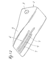
- the work surface 4 of several longitudinal ribs 5 has.
- the longitudinal ribs 5 start at the Cutting edge 1 of the tooth cap and end at the as Fastening area serving end area of the Tooth cap.
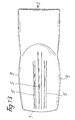
- the bottom of the tooth cap, the is shown in particular in FIG essentially just trained.
- This work surface 6 has longitudinal grooves 7 which extend from the cutting edge 1 the tooth cap to the fastening area.
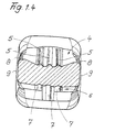
- the upper work surface 4 is transverse to Length of the tooth cap between the Wedge surface of laterally delimiting marginal edges 8 domed, with three longitudinal ribs 5 in the central region the wedge surface approximately parallel to the marginal edges 8 are trained.
- the longitudinal ribs 5 have a such a height that it is opposite the edge 8 behind, especially from the Sectional view according to Figure 1.4 can be seen.
- the longitudinal ribs 5 have a lateral one Distance from each other that is greater than the height of the ribs, but less than eight times the height of the Ribs.
- the central rib 5 has the largest Height and have the adjacent longitudinal ribs 5 a lower height.
- the longitudinal ribs go 5 via rounded transitions into the wedge surface and also into the cutting tip 1, the Ribbed ridge line is also rounded, so that in cross section gives a kind of wave profile, like 1.4 can be seen in particular.
- the on provided on the underside of the tooth cap longitudinal grooves 7 are spaced from each other by approximately the groove width formed side by side and parallel to each other, the grooves 7 in cross section a kind Form wave profile, as again from Figure 1.4 can be seen.
- the grooves are in this training 7 in the same number and approximately the same Orientation like the longitudinal ribs 5 is provided, however on the other wedge surface respectively Working surface 6 of the tooth cap.
- the side surfaces 9, which are the wedge-shaped Connect work surfaces 4,6, bulged, the Bulging from the tooth cap tip 1 to about Outlet of the longitudinal ribs 5 or longitudinal grooves 7 is provided.
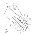
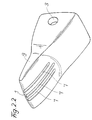
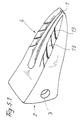
- both sides of the wedge-shaped longitudinal rib 11 four such transverse ribs 13 evenly apart spaced apart.
- the bottom of the tooth cap has a similar design, as can be seen in FIG. 2.2, as in the embodiment according to Figure 1.1 to Figure 1.4.
- the tooth cap according to Figure 3 for example as an excavator tooth or as a gripper tooth be used.
- the tooth cap tip approximately straight, transverse to the length of the tooth cap aligned cutting edge 1.
- This cutting edge can also be a rounded, transverse to the longitudinal extent of the tooth cap have an aligned shape, the Center of curvature of the cutting edge beyond the Fastening end of the tooth cap, i.e. on the Cutting edge 1 is facing away from the tooth cap.
- both working surfaces 4, 6 are designed in the same way, transverse ribs 13 also being provided there , which depart from the central longitudinal rib 11 in an arrow-like manner, the end of the transverse ribs 13 adjoining the central longitudinal rib being closer to the tip 1 of the tooth cap than the end of the transverse ribs running out at the side edge edges.
- groove-like channel structures are formed between the adjacent transverse ribs 13, which can serve to hold material or rock powder and to discharge such material against the driving direction of the tooth cap.
- the invention is not limited to the embodiments, but is variable in many ways within the scope of the disclosure.
Landscapes
- Engineering & Computer Science (AREA)
- Mining & Mineral Resources (AREA)
- Civil Engineering (AREA)
- General Engineering & Computer Science (AREA)
- Structural Engineering (AREA)
- Component Parts Of Construction Machinery (AREA)
- Placing Or Removing Of Piles Or Sheet Piles, Or Accessories Thereof (AREA)
- Soil Working Implements (AREA)
Applications Claiming Priority (2)
| Application Number | Priority Date | Filing Date | Title |
|---|---|---|---|
| DE10022629A DE10022629A1 (de) | 2000-05-11 | 2000-05-11 | Zahnklappe für Baumaschinen |
| DE10022629 | 2000-05-11 |
Publications (2)
| Publication Number | Publication Date |
|---|---|
| EP1154082A2 true EP1154082A2 (fr) | 2001-11-14 |
| EP1154082A3 EP1154082A3 (fr) | 2002-06-26 |
Family
ID=7641359
Family Applications (1)
| Application Number | Title | Priority Date | Filing Date |
|---|---|---|---|
| EP01110817A Withdrawn EP1154082A3 (fr) | 2000-05-11 | 2001-05-04 | Bonnet dentaire pour machine de chantier |
Country Status (6)
| Country | Link |
|---|---|
| US (1) | US6490816B2 (fr) |
| EP (1) | EP1154082A3 (fr) |
| KR (1) | KR20010104664A (fr) |
| CN (1) | CN1327110A (fr) |
| BR (1) | BR0101864A (fr) |
| DE (1) | DE10022629A1 (fr) |
Cited By (5)
| Publication number | Priority date | Publication date | Assignee | Title |
|---|---|---|---|---|
| WO2012166565A1 (fr) * | 2011-05-27 | 2012-12-06 | Caterpillar Inc. | Pointe de dent d'outil venant en prise avec le sol |
| US9057177B2 (en) | 2011-10-08 | 2015-06-16 | Caterpillar Inc. | Implement tooth assembly with tip and adapter |
| US9062436B2 (en) | 2011-10-07 | 2015-06-23 | Caterpillar Inc. | Implement tooth assembly with tip and adapter |
| US10041230B2 (en) | 2011-10-08 | 2018-08-07 | Caterpillar Inc. | Implement tooth assembly with tip and adapter |
| US10060100B2 (en) | 2011-10-10 | 2018-08-28 | Caterpillar Inc. | Implement tooth assembly with tip and adapter |
Families Citing this family (20)
| Publication number | Priority date | Publication date | Assignee | Title |
|---|---|---|---|---|
| US20040111927A1 (en) * | 2002-12-12 | 2004-06-17 | Livesay Richard E. | Tip and adapter assembly |
| USD527029S1 (en) * | 2004-06-14 | 2006-08-22 | H&L Tooth Company | Ground engaging tooth |
| US8191291B2 (en) * | 2008-07-09 | 2012-06-05 | Esco Corporation | Wear member for excavating equipment |
| US7818902B2 (en) * | 2008-11-12 | 2010-10-26 | H & L Tooth Company | Ground engaging digging tooth |
| US7980011B2 (en) * | 2009-03-23 | 2011-07-19 | Black Cat Blades Ltd. | Fully stabilized excavator tooth attachment |
| CN102733446A (zh) * | 2011-04-15 | 2012-10-17 | 斗山工程机械(中国)有限公司 | 一种挖掘机铲斗及其斗齿 |
| US9957691B2 (en) * | 2014-07-29 | 2018-05-01 | Caterpillar Inc. | Wear component for ground engaging tool |
| US9556595B2 (en) * | 2014-08-05 | 2017-01-31 | Caterpillar Inc. | High performance implement wear member |
| DE102014115209A1 (de) * | 2014-10-20 | 2016-04-21 | Amazonen-Werke H. Dreyer Gmbh & Co. Kg | Bodenbearbeitungswerkzeug |
| NO2780599T3 (fr) * | 2014-11-13 | 2018-08-04 | ||
| CN104612203B (zh) * | 2015-02-03 | 2017-07-28 | 大连裕工耐磨技术发展有限公司 | 一种具有外置激冷加强筋高耐磨挖掘机斗齿 |
| CN104878796A (zh) * | 2015-05-06 | 2015-09-02 | 柳州金茂机械有限公司 | 挖掘机铲斗 |
| US9644348B2 (en) * | 2015-08-12 | 2017-05-09 | Caterpillar Inc. | Ground engaging tooth assemblies |
| CN105507363A (zh) * | 2015-12-03 | 2016-04-20 | 天津市中机雄风机械有限公司 | 一种斗齿 |
| US10889966B2 (en) * | 2018-04-13 | 2021-01-12 | Caterpillar Inc. | Drafted tool bit and blade assembly |
| US11732445B2 (en) | 2018-04-13 | 2023-08-22 | Caterpillar Inc. | Retention system for attaching tool bits to a blade assembly |
| US11766003B2 (en) * | 2020-02-04 | 2023-09-26 | Capital D'investissement Carrier Inc. | Excavating assembly and tree felling head including same |
| US20250250781A1 (en) * | 2024-02-02 | 2025-08-07 | Caterpillar Inc. | Wear member having double scoop-rib |
| US20250250782A1 (en) * | 2024-02-02 | 2025-08-07 | Caterpillar Inc. | Wear member having curved wall scratching tip portion |
| DE102024111644A1 (de) * | 2024-04-25 | 2025-10-30 | Bauer Maschinen Gmbh | Abtragszahn und verfahren zum abtragen von boden |
Family Cites Families (23)
| Publication number | Priority date | Publication date | Assignee | Title |
|---|---|---|---|---|
| US1333394A (en) * | 1919-10-06 | 1920-03-09 | Taylor Wharton Iron | Dipper-tooth |
| US2247202A (en) * | 1940-08-07 | 1941-06-24 | American Brake Shoe & Foundry | Replaceable tooth for excavating implements and the like |
| US2360315A (en) * | 1943-07-14 | 1944-10-17 | Clarence W Campbell | Drag line shovel tooth |
| US3021626A (en) * | 1958-01-21 | 1962-02-20 | Esco Corp | Scraper blade |
| US2968880A (en) * | 1959-02-20 | 1961-01-24 | Gerald A M Petersen | Reversible tooth having resilient retaining means |
| US3300883A (en) * | 1963-10-21 | 1967-01-31 | Petersen | Reversible digging tooth with three cutting edges |
| US3312002A (en) * | 1964-01-13 | 1967-04-04 | Petersen Gerald A | Tooth for earth digging equipment |
| US3286379A (en) * | 1964-01-13 | 1966-11-22 | Petersen Gerald A | Digging tooth with corrugated cross-section |
| US3325926A (en) * | 1964-03-09 | 1967-06-20 | Mid Continent Steel Casting Co | Digger tooth and assembly for an excavating apparatus |
| US3309801A (en) * | 1964-05-05 | 1967-03-21 | Abex Corp | Repointer |
| US3444633A (en) * | 1966-09-06 | 1969-05-20 | Hensley Equipment Co Inc | Two-part excavating tooth |
| US3736676A (en) * | 1972-02-10 | 1973-06-05 | Pengo Corp | Excavating tooth having outwardly slanted ribs |
| CH588601A5 (fr) * | 1975-02-21 | 1977-06-15 | Zepf Hans Rudolf | |
| US3959901A (en) * | 1975-06-30 | 1976-06-01 | Caterpillar Tractor Co. | High strength earth working penetration tooth |
| DE2744497C3 (de) * | 1977-10-04 | 1982-11-04 | Intertractor Viehmann GmbH & Co, 5820 Gevelsberg | Schaufelzahn für Bagger o.dgl. |
| SU883286A1 (ru) * | 1980-01-17 | 1981-11-23 | Научно-Исследовательский И Проектно-Конструкторский Институт По Добыче Полезных Ископаемых Открытым Способом Кузнецкий Филиал | Зуб рабочего органа землеройной машины |
| SE8306787L (sv) * | 1983-12-08 | 1985-06-09 | Rainer August Hilden | Grevtand for grevmaskiner, skogskultivatorer och liknande maskiner |
| DE3520370A1 (de) * | 1985-06-07 | 1986-12-11 | Carl Falkenroth Söhne GmbH & Co KG, 5885 Schalksmühle | Werkzeugaggregat fuer baggerloeffel, frontlader, greifer oder dergleichen |
| JP2596106B2 (ja) * | 1988-12-27 | 1997-04-02 | 住友重機械鋳鍛株式会社 | 複合掘削ツース |
| FR2667088B1 (fr) * | 1990-09-20 | 1994-10-14 | Technogenia Sa | Dent pour outil d'excavation. |
| US5111600A (en) * | 1991-07-30 | 1992-05-12 | Caterpillar Inc. | Tooth with hard material applied to selected surfaces |
| US5502905A (en) * | 1994-04-26 | 1996-04-02 | Caterpillar Inc. | Tooth having abrasion resistant material applied thereto |
| BR7701861U (pt) * | 1997-05-30 | 1999-07-06 | Vale Do Rio Doce Co | Disposição construtiva introduzida em dente de caçambas de recuperadora de minério |
-
2000
- 2000-05-11 DE DE10022629A patent/DE10022629A1/de not_active Withdrawn
-
2001
- 2001-05-04 EP EP01110817A patent/EP1154082A3/fr not_active Withdrawn
- 2001-05-10 BR BR0101864-7A patent/BR0101864A/pt not_active Application Discontinuation
- 2001-05-10 US US09/853,091 patent/US6490816B2/en not_active Expired - Fee Related
- 2001-05-11 CN CN01121806A patent/CN1327110A/zh active Pending
- 2001-05-11 KR KR1020010025711A patent/KR20010104664A/ko not_active Withdrawn
Cited By (6)
| Publication number | Priority date | Publication date | Assignee | Title |
|---|---|---|---|---|
| WO2012166565A1 (fr) * | 2011-05-27 | 2012-12-06 | Caterpillar Inc. | Pointe de dent d'outil venant en prise avec le sol |
| US9062436B2 (en) | 2011-10-07 | 2015-06-23 | Caterpillar Inc. | Implement tooth assembly with tip and adapter |
| US9057177B2 (en) | 2011-10-08 | 2015-06-16 | Caterpillar Inc. | Implement tooth assembly with tip and adapter |
| US9624651B2 (en) | 2011-10-08 | 2017-04-18 | Caterpillar Inc. | Implement tooth assembly with tip and adapter |
| US10041230B2 (en) | 2011-10-08 | 2018-08-07 | Caterpillar Inc. | Implement tooth assembly with tip and adapter |
| US10060100B2 (en) | 2011-10-10 | 2018-08-28 | Caterpillar Inc. | Implement tooth assembly with tip and adapter |
Also Published As
| Publication number | Publication date |
|---|---|
| US6490816B2 (en) | 2002-12-10 |
| BR0101864A (pt) | 2001-12-18 |
| KR20010104664A (ko) | 2001-11-26 |
| DE10022629A1 (de) | 2001-11-15 |
| US20020043010A1 (en) | 2002-04-18 |
| EP1154082A3 (fr) | 2002-06-26 |
| CN1327110A (zh) | 2001-12-19 |
Similar Documents
| Publication | Publication Date | Title |
|---|---|---|
| EP1154082A2 (fr) | Bonnet dentaire pour machine de chantier | |
| DE2733543C3 (de) | Baggertieflöffel | |
| DE2514070A1 (de) | Baggerloeffel | |
| DE2140111A1 (de) | Zweiteilige Schaufelkante für Flachbagger od. dgl | |
| DE1941980A1 (de) | Baggerzahn | |
| EP0649945A1 (fr) | Dent d'excavatrice | |
| DE4201924C2 (de) | Schlepp-Schürfkübel | |
| DE4015627A1 (de) | Brecherwerk | |
| DE1458627A1 (de) | Erdbohrgeraet | |
| DE2261910A1 (de) | Befestigungsvorrichtung fuer einen grabzahn od. dgl | |
| DE2004922A1 (de) | Erdbearbeitungswerkzeug | |
| DE2202482C3 (de) | Baggerlöffel | |
| EP1468790B1 (fr) | Burin plat | |
| DE19748122B4 (de) | Stegglied für Reifenketten, insbesondere für Reifenschutzketten | |
| DE10133948A1 (de) | Spitzmeissel 3-seitige Schneide | |
| CH670418A5 (fr) | ||
| DE2222734C3 (fr) | ||
| AT368602B (de) | Fels- bzw. gesteinsbrecher-werkzeug | |
| DE2806442A1 (de) | Baggerzinken | |
| DE9419318U1 (de) | Baggerzahn | |
| DE4418757C2 (de) | Adapter und Kappe für ein Müllverdichtungsfahrzeug | |
| DE1634523A1 (de) | Bohrerkopf mit radialen Armen | |
| DE245750C (fr) | ||
| DE207717C (fr) | ||
| DE2041218A1 (de) | Geraet zum Aufreissen des Erdbodens mittels Schlagkraft |
Legal Events
| Date | Code | Title | Description |
|---|---|---|---|
| PUAI | Public reference made under article 153(3) epc to a published international application that has entered the european phase |
Free format text: ORIGINAL CODE: 0009012 |
|
| AK | Designated contracting states |
Kind code of ref document: A2 Designated state(s): AT BE CH CY DE DK ES FI FR GB GR IE IT LI LU MC NL PT SE TR |
|
| AX | Request for extension of the european patent |
Free format text: AL;LT;LV;MK;RO;SI |
|
| PUAL | Search report despatched |
Free format text: ORIGINAL CODE: 0009013 |
|
| AK | Designated contracting states |
Kind code of ref document: A3 Designated state(s): AT BE CH CY DE DK ES FI FR GB GR IE IT LI LU MC NL PT SE TR |
|
| AX | Request for extension of the european patent |
Free format text: AL;LT;LV;MK;RO;SI |
|
| 17P | Request for examination filed |
Effective date: 20020928 |
|
| 17Q | First examination report despatched |
Effective date: 20021206 |
|
| AKX | Designation fees paid |
Designated state(s): AT BE CH CY DE DK ES FI FR GB GR IE IT LI LU MC NL PT SE TR |
|
| STAA | Information on the status of an ep patent application or granted ep patent |
Free format text: STATUS: THE APPLICATION HAS BEEN WITHDRAWN |
|
| 18W | Application withdrawn |
Effective date: 20030806 |