EP1154190B1 - Raccord de tuyaux - Google Patents
Raccord de tuyaux Download PDFInfo
- Publication number
- EP1154190B1 EP1154190B1 EP01304106A EP01304106A EP1154190B1 EP 1154190 B1 EP1154190 B1 EP 1154190B1 EP 01304106 A EP01304106 A EP 01304106A EP 01304106 A EP01304106 A EP 01304106A EP 1154190 B1 EP1154190 B1 EP 1154190B1
- Authority
- EP
- European Patent Office
- Prior art keywords
- tube
- coupling body
- coupling
- cap
- engage
- Prior art date
- Legal status (The legal status is an assumption and is not a legal conclusion. Google has not performed a legal analysis and makes no representation as to the accuracy of the status listed.)
- Expired - Lifetime
Links
- 230000008878 coupling Effects 0.000 title claims description 85
- 238000010168 coupling process Methods 0.000 title claims description 85
- 238000005859 coupling reaction Methods 0.000 title claims description 85
- 230000014759 maintenance of location Effects 0.000 claims description 2
- 239000011324 bead Substances 0.000 description 8
- 230000007246 mechanism Effects 0.000 description 4
- 230000000712 assembly Effects 0.000 description 1
- 238000000429 assembly Methods 0.000 description 1
- 230000000903 blocking effect Effects 0.000 description 1
- 239000012530 fluid Substances 0.000 description 1
- 239000000446 fuel Substances 0.000 description 1
- 238000003780 insertion Methods 0.000 description 1
- 230000037431 insertion Effects 0.000 description 1
- 238000007689 inspection Methods 0.000 description 1
- 238000007789 sealing Methods 0.000 description 1
- 125000006850 spacer group Chemical group 0.000 description 1
- 238000012795 verification Methods 0.000 description 1
- 230000000007 visual effect Effects 0.000 description 1
Images


Classifications
-
- F—MECHANICAL ENGINEERING; LIGHTING; HEATING; WEAPONS; BLASTING
- F16—ENGINEERING ELEMENTS AND UNITS; GENERAL MEASURES FOR PRODUCING AND MAINTAINING EFFECTIVE FUNCTIONING OF MACHINES OR INSTALLATIONS; THERMAL INSULATION IN GENERAL
- F16L—PIPES; JOINTS OR FITTINGS FOR PIPES; SUPPORTS FOR PIPES, CABLES OR PROTECTIVE TUBING; MEANS FOR THERMAL INSULATION IN GENERAL
- F16L37/00—Couplings of the quick-acting type
- F16L37/08—Couplings of the quick-acting type in which the connection between abutting or axially overlapping ends is maintained by locking members
- F16L37/12—Couplings of the quick-acting type in which the connection between abutting or axially overlapping ends is maintained by locking members using hooks, pawls, or other movable or insertable locking members
-
- F—MECHANICAL ENGINEERING; LIGHTING; HEATING; WEAPONS; BLASTING
- F16—ENGINEERING ELEMENTS AND UNITS; GENERAL MEASURES FOR PRODUCING AND MAINTAINING EFFECTIVE FUNCTIONING OF MACHINES OR INSTALLATIONS; THERMAL INSULATION IN GENERAL
- F16L—PIPES; JOINTS OR FITTINGS FOR PIPES; SUPPORTS FOR PIPES, CABLES OR PROTECTIVE TUBING; MEANS FOR THERMAL INSULATION IN GENERAL
- F16L37/00—Couplings of the quick-acting type
- F16L37/08—Couplings of the quick-acting type in which the connection between abutting or axially overlapping ends is maintained by locking members
- F16L37/084—Couplings of the quick-acting type in which the connection between abutting or axially overlapping ends is maintained by locking members combined with automatic locking
- F16L37/098—Couplings of the quick-acting type in which the connection between abutting or axially overlapping ends is maintained by locking members combined with automatic locking by means of flexible hooks
- F16L37/0985—Couplings of the quick-acting type in which the connection between abutting or axially overlapping ends is maintained by locking members combined with automatic locking by means of flexible hooks the flexible hook extending radially inwardly from an outer part and engaging a bead, recess or the like on an inner part
-
- F—MECHANICAL ENGINEERING; LIGHTING; HEATING; WEAPONS; BLASTING
- F16—ENGINEERING ELEMENTS AND UNITS; GENERAL MEASURES FOR PRODUCING AND MAINTAINING EFFECTIVE FUNCTIONING OF MACHINES OR INSTALLATIONS; THERMAL INSULATION IN GENERAL
- F16L—PIPES; JOINTS OR FITTINGS FOR PIPES; SUPPORTS FOR PIPES, CABLES OR PROTECTIVE TUBING; MEANS FOR THERMAL INSULATION IN GENERAL
- F16L2201/00—Special arrangements for pipe couplings
- F16L2201/10—Indicators for correct coupling
Definitions
- This invention relates to couplings for receiving tubes or stuffer pins or the like such as disclosed in EP-A-00300504.8 and EP-A-756125.
- US-A-5,658,020 discloses a quick connector for fast connection of fluid carrying assemblies and includes a connector body for the connector components and a redundant clip, which is adapted to engage an upset bead of the male tube.
- the redundant clip is generally L-shaped and includes a retaining head that is inserted into the connector body and is adapted to engage the upset bead.
- a body portion which extends along the side of the connector body and in the preferred embodiment is contoured to mate with the , connector body, extends between the retaining head and a base member.
- the base includes a camming edge for facilitating the insertion of the retainer head into the connector body.
- WO 98/38 450 A discloses a releasable connector for connecting tubing such as used in fuel lines and has a display member to indicate when positive locking has occurred.
- the display member is attached to the outside of the housing of the connector and has a strap supporting a cover portion.
- the cover portion has a pair of resilient flanges which are insertable into an opening in the housing of the connector.
- the flanges extend into a chamber to engage an annular ring of a conventional male tube end.
- the annular portion of the tube end displaces the flanges of the display member after passing through a locking member contained in the housing of the connector. In this way, the tamper indicator indicates that the tube end has been positively received in the locking position.
- the European Patent Publication No. 0829671 describes and illustrates a number of connectors for latching engagement with tubes or stuffer pins in which a tube must be pressed into the connector body for the latching arrangement provided to operate and retain the tube in the body.
- a raised bead is provided on the tube with which the latch in the coupling body engages.
- US-A-5,931,509 discloses a tube coupling comprising all the features of the preamble of claim 1, having a connection verification and secondary latch device.
- the connector ring has a primary latching mechanism which engages a first annular projection on the tube and a second latching mechanism which engages a second annular projection on the tube.
- the latching mechanisms extend outside of the housing connector which receives the conduit thus allowing an inspection of the assembly to ensure that a complete connection by both latching mechanisms has been accomplished.
- the invention provides a connector assembly, comprising a tubular conduit including a first end having first and second annular projections disposed a predetermined distance from said first end, a retainer element including primary latching means releasably engageable with said first annular projection and secondary latching means extending from and attached to said primary latching means, means for sealing the connector assembly, and a housing for receiving said first end of said tubular conduit, said housing including at least one blocking wall, whereby upon fully inserting said tubular conduit within said housing, said primary latching means engage said first annular projection of said tubular conduit and said secondary latching means engage said second annular projection of said tubular conduit.
- This invention provides a coupling for a tube having a feature spaced from an end of the tube for engagement by latching devices, the coupling comprising a coupling body having a throughway open at one end to receive an end portion of the tube, a seal mounted in the coupling body at a location spaced from said open end thereof to engage and seal with the outer periphery of the tube, a first latching device disposed within the coupling body having at least one latch to engage automatically with the feature on the tube when the tube has been inserted sufficiently into the throughway to engage with the seal to thereby retain the tube in the coupling body, and a second, manually operable latching device disposed externally of the coupling body mounted on the coupling body, manually moveable between one operative position in which the second latching device is engageable with the feature on the tube when the tube has been inserted into the coupling body sufficiently for the first latching device to engage to provide a second independent retention for the tube in the coupling body, and an inoperative position withdrawn from the tube to allow release of the tube from
- the cap and coupling body Preferably have slots through which the detent on the leg can project to engage a feature on the tube which is also engaged by the first latching device within the coupling body.
- interengaging abutment means are provided on the detent and coupling body to retain the detent engaged in said slots in the coupling body and cap.
- the leg is hingedly mounted to the cap and when the tube is inserted into the coupling body the second latching device is arranged to engage a second feature on the tube which is located externally of the coupling body thereby to retain the tube in the coupling body.
- the detent on the arm comprises a C-shaped clip to snap around the tube.
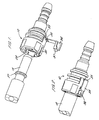
- the coupling comprises a coupling body 10 having a stepped throughway 11 open at one end 12 of the coupling body to receive a tube end fitting indicated at 13.
- the tube end fitting in this case is a standard male end form to SAE (Society of Automotive Engineers) J2044. Other similar fittings are equally applicable.
- the throughway 11 is stepped at 14 to an enlonged diameter portion 15 to receive the tube end 13 with a close or interference fit.
- the throughway is stepped at 16 to a second enlarged diameter portion 17 in which a pair of 0-ring seals 18 are located with a spacer 19 between them to seal on the outside of the tube end 13.
- the throughway has a further step 20 to an enlarged diameter portion 21 which extends through to the open end of the throughway at 12.
- a first internal latch is located within the coupling body 10 and comprises a sleeve 22 extending through the enlarged diameter portion 21 of the throughway 21 and having a reduced diameter end portion 23 to engage in portion 17 of the throughway.
- the sleeve has three integral resilient legs 24 disposed over three quarters of the circumference of the sleeve and projecting towards the open end of the coupling.
- the legs have latch members 25 at their distal ends which have outwardly extending abutments which engage in radial opening 26 through the wall of the coupling body and have inwardly projecting teeth 25a to engage a raised annular abutment or bead 27 on the tube end.
- European patent publication no. 0829671 for a more detailed description of the form of the latch members and the manner of their engagement with the raised abutment on the tube end and in the openings 26 of the coupling body wall to retain the tube end in the coupling.
- the sleeve 22 has integral struts 28 projecting between the teeth to the open end of the coupling body.
- the struts are formed integrally with an end cap 30 encircling the end of the coupling body and which is adjustable axially on the coupling body to adjust the position of the internal latches for release of a tube end from the coupling body as described in our previous European publication.
- the legs/internal latch members in the coupling body are provided over three quarters of the circumference of the sleeve.
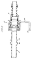
- the remaining quarter of the sleeve is disposed opposite a slot 31 formed with the wall of the coupling body and a corresponding slot 32 formed in the wall of the cap.
- the wall of the cap has an extension 33 in alignment with the slot 30 and a leg 34 is attached to the extension by an integral hinge 35.
- the leg has a detent 36 at its distal end shaped to extend through the slots in the cap and coupling body and to engage the end of the tube behind the raised rib 27 to provide a secondary, external latch for holding the tube in place in the coupling body.
- the end of the detent 36 is radiused as shown at 37 with a corresponding radius to the tube end to provide a close engagement between the abutment and tube.
- the detent is formed with abutments 36a which snap behind abutments on either side of the slot in the coupling body to retain the detent in the engaged position.
- the hinge 35 between the leg 34 and cap extension 33 has a moulded characteristic such that the leg 34 snaps towards the coupling body when adjacent the body and snaps outwardly of the body when withdrawn beyond an intermediate position in its travel. The leg then stands outwardly of the coupling body and provides a clear visual or tactile indication that it is not engaged.
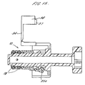
- Figures 7 to 11 show a broadly similar arrangement except that in this case the tube end 13 has a second raised bead 40 beyond the first bead or abutment 27 and the detent 36 on the leg 34 is arranged to project beyond body in the closed position and to engage the tube end 13 beyond the second bead 40.
- the abutment does not fit between slots in the cap and coupling body so the coupling body may be provided with four internal latches to engage the bead 27 rather than three of the first embodiments.
- the detent is in the form of a C-shaped clip which is a snap fit on the tube end. The arrangement is otherwise much the same as that of Figure 1.
- Figures 1 to 6 can also be adapted to have four latch members within the coupling body and one pair of members spaced sufficiently to accommodate the external manual latch between them.
- FIGs 12 to 15 shows similar arrangements applied to stuffer pins rather than tube ends.
Landscapes
- Engineering & Computer Science (AREA)
- General Engineering & Computer Science (AREA)
- Mechanical Engineering (AREA)
- Quick-Acting Or Multi-Walled Pipe Joints (AREA)
Claims (5)
- Raccord pour un tuyau (13) ayant un élément (27) espacé d'une extrémité du tuyau pour un engagement par des dispositifs de verrouillage, le raccord comprenant un corps de raccord (10) ayant un passage direct (11) ouvert à une extrémité (12) pour recevoir une partie d'extrémité du tuyau ;
un joint d'étanchéité (18) monté dans le corps de raccord à un emplacement (17) espacé de ladite extrémité ouverte de celui-ci, pour être engagé avec et rendre étanche la périphérie externe du tuyau (13),
un premier dispositif de verrouillage (25) disposé dans le corps de raccord ayant au moins un verrou (25a) pour s'engager automatiquement avec l'élément (27) sur le tuyau lorsque le tuyau a été suffisamment inséré dans le passage direct pour être engagé avec le joint d'étanchéité pour retenir ainsi le tuyau dans le corps de raccord,
et un second dispositif de verrouillage (30, 31, 32) pouvant être actionné manuellement, disposé à l'extérieur du corps de raccord, monté sur le corps de raccord, manuellement mobile entre une position de fonctionnement dans laquelle le second dispositif de verrouillage peut être engagé avec l'élément sur le tuyau lorsque le tuyau a été inséré suffisamment dans le corps de raccord pour que le premier dispositif de verrouillage s'engage pour fournir une seconde retenue indépendante pour le tuyau dans le corps de raccord, et une position de non-fonctionnement retirée du tuyau pour permettre le retrait du tuyau du corps de raccord,
ledit second dispositif de verrouillage comprend un capuchon d'extrémité monté sur le corps de raccord, le capuchon (30) ayant une ouverture dans son extrémité pour que le tuyau s'étende à travers le corps de raccord, caractérisé en ce que ledit capuchon d'extrémité (30) encercle l'extrémité ouverte du corps de raccord et a une patte de montage (34) sur laquelle le second verrou (36) est positionné, la patte étant articulée par rapport au capuchon pour se déplacer entre lesdites positions de fonctionnement et de non-fonctionnement sur le capuchon, la patte de montage articulée comprenant un ressort (35) solidaire adapté pour solliciter le second dispositif de verrouillage vers la position de non-fonctionnement retirée du tuyau lorsque le second dispositif de verrouillage est dégagé d'un tuyau dans le corps de raccord. - Raccord selon la revendication 1, caractérisé en ce que le capuchon et le corps de raccord ont des fentes (32, 31) à travers lesquelles la détente (36) sur la patte (34) peut faire saillie pour engager un élément sur le tuyau qui est également engagé par le premier dispositif de verrouillage à l'intérieur du corps de raccord.
- Raccord selon la revendication 2, dans lequel sont prévus des moyens de butée à mise en prise mutuelle (36a) sur la détente (36) et le corps de raccord pour retenir la détente engagée dans lesdites fentes dans le corps de raccord et le capuchon.
- Raccord selon la revendication 1, caractérisé en ce que la patte (34) est montée de manière articulée sur le capuchon (30) et lorsque le tuyau est inséré dans le corps de raccord, le second dispositif de verrouillage (36) est agencé pour engager un second élément sur le tuyau qui est situé à l'extérieur du corps de raccord pour retenir ainsi le tuyau dans le corps de raccord.
- Raccord selon la revendication 4, dans lequel la détente sur le bras (34) comprend un clip en forme de C (41) pour s'enclencher autour du tuyau.
Applications Claiming Priority (2)
| Application Number | Priority Date | Filing Date | Title |
|---|---|---|---|
| GB0011317 | 2000-05-10 | ||
| GBGB0011317.5A GB0011317D0 (en) | 2000-05-10 | 2000-05-10 | Tube couplings |
Publications (3)
| Publication Number | Publication Date |
|---|---|
| EP1154190A2 EP1154190A2 (fr) | 2001-11-14 |
| EP1154190A3 EP1154190A3 (fr) | 2003-01-15 |
| EP1154190B1 true EP1154190B1 (fr) | 2005-10-12 |
Family
ID=9891353
Family Applications (1)
| Application Number | Title | Priority Date | Filing Date |
|---|---|---|---|
| EP01304106A Expired - Lifetime EP1154190B1 (fr) | 2000-05-10 | 2001-05-04 | Raccord de tuyaux |
Country Status (9)
| Country | Link |
|---|---|
| US (1) | US6863314B2 (fr) |
| EP (1) | EP1154190B1 (fr) |
| JP (1) | JP2002005374A (fr) |
| AU (1) | AU779670B2 (fr) |
| BR (1) | BR0101857B1 (fr) |
| DE (1) | DE60113912T2 (fr) |
| ES (1) | ES2250311T3 (fr) |
| GB (1) | GB0011317D0 (fr) |
| NZ (1) | NZ511546A (fr) |
Cited By (1)
| Publication number | Priority date | Publication date | Assignee | Title |
|---|---|---|---|---|
| US12584574B2 (en) | 2023-02-02 | 2026-03-24 | Martinrea International US Inc. | Coolant quick connector with graphene, integrated latch and integrated O-ring retainer |
Families Citing this family (69)
| Publication number | Priority date | Publication date | Assignee | Title |
|---|---|---|---|---|
| US6851725B2 (en) * | 2001-11-20 | 2005-02-08 | Cooper Technology Services, Llc | Secondary retention clip for fluid tube connection |
| ATE458958T1 (de) * | 2002-03-05 | 2010-03-15 | Sakura Rubber | Kupplungsvorrichtung mit lösungsverhinderungskonstruktion |
| DE10229004B4 (de) * | 2002-06-28 | 2005-09-29 | Veritas Ag | Leitungseinrichtung |
| US7316428B2 (en) * | 2002-10-07 | 2008-01-08 | Tokai Rubber Industries, Ltd. | Connection verifying device and connection verifying structure for a pipe and a connector |
| FR2847647B1 (fr) * | 2002-11-25 | 2007-10-05 | Raccord a securite augmentee | |
| US20050082828A1 (en) | 2003-09-12 | 2005-04-21 | Wicks Jeffrey C. | Releasable connection assembly for joining tubing sections |
| JP4228922B2 (ja) | 2004-01-27 | 2009-02-25 | 東海ゴム工業株式会社 | クイックコネクタ |
| DE102004039857A1 (de) | 2004-08-17 | 2006-02-23 | Veritas Ag | Kupplungseinrichtung mit magnetischer Verriegelung |
| US7967342B2 (en) * | 2005-03-01 | 2011-06-28 | Ti Group Automotive Systems, Llc | Anti-rotation quick connector |
| US7448653B2 (en) | 2005-06-10 | 2008-11-11 | Value Plastics, Inc. | Female connector for releasable coupling with a male connector defining a fluid conduit |
| US7806139B2 (en) | 2006-01-20 | 2010-10-05 | Value Plastics, Inc. | Fluid conduit coupling assembly having male and female couplers with integral valves |
| GB0624784D0 (en) | 2006-12-12 | 2007-01-17 | Guest John Int Ltd | Improvements in or relating to tube couplings |
| JP4767912B2 (ja) * | 2007-06-12 | 2011-09-07 | 本田技研工業株式会社 | コネクタの脱落防止構造およびコネクタの脱落防止方法 |
| DE102007053096B4 (de) * | 2007-11-07 | 2024-12-05 | Continental Automotive Technologies GmbH | Scheibenreinigungsanlage für ein Kraftfahrzeug |
| USD654573S1 (en) | 2007-11-19 | 2012-02-21 | Value Plastics, Inc. | Female quick connect fitting |
| GB0723646D0 (en) * | 2007-12-03 | 2008-01-16 | Guest John Int Ltd | Tube couplings |
| GB0809685D0 (en) * | 2008-05-28 | 2008-07-02 | Guest John Int Ltd | Improvements in or relating to tube couplings |
| USD634840S1 (en) | 2008-07-03 | 2011-03-22 | Value Plastics, Inc. | Female body of connector for fluid tubing |
| USD630320S1 (en) | 2008-07-03 | 2011-01-04 | Value Plastics, Inc. | Connector for fluid tubing |
| USD629894S1 (en) | 2008-07-03 | 2010-12-28 | Value Plastics, Inc. | Male body of connector for fluid tubing |
| US8235426B2 (en) | 2008-07-03 | 2012-08-07 | Nordson Corporation | Latch assembly for joining two conduits |
| US20100052315A1 (en) * | 2008-08-28 | 2010-03-04 | Ti Group Automotive Systems, Llc | Quick connector coupling with lateral stabilization |
| USD655393S1 (en) | 2009-06-23 | 2012-03-06 | Value Plastics, Inc. | Multi-port valve |
| USD783815S1 (en) | 2009-12-09 | 2017-04-11 | General Electric Company | Male dual lumen bayonet connector |
| USD649240S1 (en) | 2009-12-09 | 2011-11-22 | Value Plastics, Inc. | Male dual lumen bayonet connector |
| USD650478S1 (en) | 2009-12-23 | 2011-12-13 | Value Plastics, Inc. | Female dual lumen connector |
| US10711930B2 (en) | 2009-12-09 | 2020-07-14 | Nordson Corporation | Releasable connection assembly |
| US9388929B2 (en) | 2009-12-09 | 2016-07-12 | Nordson Corporation | Male bayonet connector |
| KR101715636B1 (ko) | 2009-12-23 | 2017-03-13 | 노드슨 코포레이션 | 프로파일 리드-인을 갖는 유체 커넥터 래치 |
| EP2516914B1 (fr) | 2009-12-23 | 2018-09-05 | General Electric Company | Verrouillage à bouton avec ressorts en porte-à-faux moulés en une seule pièce |
| US8833733B2 (en) | 2010-01-21 | 2014-09-16 | Automatic Switch Company | Valve connections |
| JP5638261B2 (ja) * | 2010-02-18 | 2014-12-10 | 三菱重工業株式会社 | 流体用継手 |
| GB201010501D0 (en) | 2010-06-22 | 2010-08-04 | Guest John Int Ltd | A tube coupling |
| DE102010031662A1 (de) * | 2010-07-22 | 2012-01-26 | Bayerische Motoren Werke Aktiengesellschaft | Sicherungseinrichtung für eine Verbindungsanordnung |
| CN103348172B (zh) * | 2011-02-08 | 2015-07-29 | 艾莫股份公司 | 联接装置 |
| USD663022S1 (en) | 2011-02-11 | 2012-07-03 | Nordson Corporation | Male body of connector for fluid tubing |
| USD652511S1 (en) | 2011-02-11 | 2012-01-17 | Value Plastics, Inc. | Female body of connector for fluid tubing |
| USD652510S1 (en) | 2011-02-11 | 2012-01-17 | Value Plastics, Inc. | Connector for fluid tubing |
| USD699840S1 (en) | 2011-07-29 | 2014-02-18 | Nordson Corporation | Male body of connector for fluid tubing |
| USD699841S1 (en) | 2011-07-29 | 2014-02-18 | Nordson Corporation | Female body of connector for fluid tubing |
| USD698440S1 (en) | 2011-07-29 | 2014-01-28 | Nordson Corporation | Connector for fluid tubing |
| US8960726B2 (en) | 2011-11-23 | 2015-02-24 | Parker-Hannifin Corporation | Coupling lock mechanism |
| US9217524B2 (en) | 2011-11-23 | 2015-12-22 | Parker-Hannifin Corporation | Coupling lock mechanism |
| USD709612S1 (en) | 2011-12-23 | 2014-07-22 | Nordson Corporation | Female dual lumen connector |
| GB201205575D0 (en) | 2012-03-29 | 2012-05-16 | Guest John Int Ltd | Improvements in or relating to tube couplings |
| US9016314B2 (en) * | 2012-05-25 | 2015-04-28 | Asatek Danmark A/S | Fluid connector for a cooling system |
| DE102013016855B4 (de) * | 2013-10-10 | 2019-07-11 | Voss Automotive Gmbh | Mehrteilige Leitung |
| GB201317952D0 (en) | 2013-10-10 | 2013-11-27 | Guest John Int Ltd | A connector for connecting to a tube |
| GB201317990D0 (en) | 2013-10-11 | 2013-11-27 | Guest John Int Ltd | A conncetor |
| USD733842S1 (en) * | 2014-06-19 | 2015-07-07 | Life Technologies Corporation | Tube connector |
| US10422459B2 (en) | 2015-01-14 | 2019-09-24 | Norma U.S. Holding Llc | Conduit connector with a primary and secondary latch |
| US9671052B2 (en) * | 2015-10-27 | 2017-06-06 | Whirlpool Corporation | Collet securing device for joining two fluid lines and providing lateral support at the connection of the two fluid lines |
| US10557469B2 (en) | 2016-03-22 | 2020-02-11 | Whirlpool Corporation | Multi-outlet fluid flow system for an appliance incorporating a bi-directional motor |
| USD838366S1 (en) | 2016-10-31 | 2019-01-15 | Nordson Corporation | Blood pressure connector |
| US10281075B2 (en) | 2016-11-15 | 2019-05-07 | Campbell Fittings, Inc. | Quick disconnect coupling for conduit |
| US10655266B2 (en) | 2016-11-30 | 2020-05-19 | Whirlpool Corporation | Lint processing fluid pump for a laundry appliance |
| US10619289B2 (en) | 2017-02-27 | 2020-04-14 | Whirlpool Corporation | Self cleaning diverter valve |
| US10662574B2 (en) | 2017-02-27 | 2020-05-26 | Whirlpool Corporation | Self cleaning heater exchanger plate |
| US10480117B2 (en) | 2017-02-27 | 2019-11-19 | Whirlpool Corporation | Self cleaning sump cover |
| US10634412B2 (en) | 2017-04-10 | 2020-04-28 | Whirlpool Corporation | Concealed upstream air tower guide vanes |
| CN107906287B (zh) * | 2017-11-15 | 2019-01-11 | 朗丝窗饰有限公司 | 用于输送高压液体的自锁合接口 |
| US10697700B2 (en) | 2018-01-17 | 2020-06-30 | Whirlpool Corporation | Refrigeration water dispensing system |
| US11209106B2 (en) | 2019-03-22 | 2021-12-28 | General Electric Company | Self-locking fluid coupling assembly |
| US11608905B2 (en) | 2019-11-01 | 2023-03-21 | TSI Products, Inc. | Modular valve system |
| USD944080S1 (en) | 2019-11-01 | 2022-02-22 | TSI Products, Inc. | Clip |
| DE102020006979B4 (de) * | 2020-11-13 | 2026-04-23 | A. Kayser Automotive Systems Gmbh | Fluidkupplung, insbesondere für Fluid führende Leitungen in Kraftfahrzeugen, Kombination aus der Fluidkupplung mit einem entsprechenden Gegenstück und Verfahren zum Herstellen einer Verbindung von zwei Fluidleitungen |
| US12104733B2 (en) * | 2021-08-13 | 2024-10-01 | Dlhbowles, Inc. | VDA connector assembly with verification |
| WO2024163324A1 (fr) * | 2023-02-02 | 2024-08-08 | Martinrea International US Inc. | Raccord rapide de liquide de refroidissement doté de graphène, verrou intégré et dispositif de retenue de joint torique intégré |
| US12607284B1 (en) * | 2025-02-18 | 2026-04-21 | Nextronics Engineering Corp. | Liquid-cooling quick connector device |
Citations (1)
| Publication number | Priority date | Publication date | Assignee | Title |
|---|---|---|---|---|
| WO1998038450A1 (fr) * | 1997-03-01 | 1998-09-03 | A. Raymond & Cie | Raccord liberable avec dispositif indicateur de montage |
Family Cites Families (19)
| Publication number | Priority date | Publication date | Assignee | Title |
|---|---|---|---|---|
| US742655A (en) * | 1903-06-20 | 1903-10-27 | John Homola | Hose-coupling. |
| US996079A (en) * | 1910-12-29 | 1911-06-27 | John Greenlund | Hose-coupling. |
| US3858915A (en) * | 1974-03-27 | 1975-01-07 | Gen Motors Corp | Snap together coupling with integral spring |
| US4648630A (en) * | 1983-02-16 | 1987-03-10 | David A. Zornes | Fire hose coupling lock |
| US4857567A (en) | 1987-07-24 | 1989-08-15 | Basf Corporation, Inmont Division | Flexible aryl alkyl epoxy resins, their amine resin derivatives and their use in electrodeposition coatings |
| JP2500247Y2 (ja) * | 1991-06-03 | 1996-06-05 | 矢崎総業株式会社 | レバ―付コネクタ |
| US5251940A (en) * | 1991-12-23 | 1993-10-12 | Aeroquip Corporation | Pipe coupling with pivoting locking member |
| US5443289A (en) | 1992-11-11 | 1995-08-22 | Guest; John D. | Tube couplings |
| US5658020A (en) * | 1993-03-23 | 1997-08-19 | Itt Corporation | Quick connector |
| US5395140A (en) * | 1993-05-13 | 1995-03-07 | Enhanced Applications, L.C. | Secondary latch and indicator for fluid coupling |
| US5401063A (en) * | 1993-07-19 | 1995-03-28 | Enhanced Applications, L.C. | Primary/secondary retainer for beaded/flared tubing |
| GB9400585D0 (en) | 1994-01-13 | 1994-03-09 | Guest John D | Improvements in or relating to tube couplings |
| US5779279A (en) * | 1994-05-24 | 1998-07-14 | Proprietary Technology, Inc. | Connection verification and secondary latch device |
| US5628531A (en) * | 1995-04-26 | 1997-05-13 | Bundy Corporation | Quick connector with secondary latch |
| DE69621292T2 (de) | 1995-07-28 | 2002-12-19 | John Guest Ltd., West Drayton | Rohrverbindung |
| GB9618922D0 (en) | 1996-09-11 | 1996-10-23 | Guest John D | Improvements in or relating to collets for coupling devices |
| US5931509A (en) * | 1996-11-19 | 1999-08-03 | Proprietary Technology, Inc. | Connection verification and secondary latch device |
| US5988693A (en) * | 1997-07-31 | 1999-11-23 | Campbell Fittings, Inc. | Safety locking coupling assembly |
| JP3799938B2 (ja) * | 2000-02-24 | 2006-07-19 | 東海ゴム工業株式会社 | コネクター用配管構造 |
-
2000
- 2000-05-10 GB GBGB0011317.5A patent/GB0011317D0/en not_active Ceased
-
2001
- 2001-05-04 EP EP01304106A patent/EP1154190B1/fr not_active Expired - Lifetime
- 2001-05-04 ES ES01304106T patent/ES2250311T3/es not_active Expired - Lifetime
- 2001-05-04 DE DE60113912T patent/DE60113912T2/de not_active Expired - Lifetime
- 2001-05-07 NZ NZ511546A patent/NZ511546A/xx unknown
- 2001-05-08 US US09/850,866 patent/US6863314B2/en not_active Expired - Lifetime
- 2001-05-09 AU AU43788/01A patent/AU779670B2/en not_active Ceased
- 2001-05-10 JP JP2001140206A patent/JP2002005374A/ja active Pending
- 2001-05-10 BR BRPI0101857-4A patent/BR0101857B1/pt not_active IP Right Cessation
Patent Citations (1)
| Publication number | Priority date | Publication date | Assignee | Title |
|---|---|---|---|---|
| WO1998038450A1 (fr) * | 1997-03-01 | 1998-09-03 | A. Raymond & Cie | Raccord liberable avec dispositif indicateur de montage |
Cited By (1)
| Publication number | Priority date | Publication date | Assignee | Title |
|---|---|---|---|---|
| US12584574B2 (en) | 2023-02-02 | 2026-03-24 | Martinrea International US Inc. | Coolant quick connector with graphene, integrated latch and integrated O-ring retainer |
Also Published As
| Publication number | Publication date |
|---|---|
| US20010054819A1 (en) | 2001-12-27 |
| EP1154190A2 (fr) | 2001-11-14 |
| JP2002005374A (ja) | 2002-01-09 |
| DE60113912D1 (de) | 2006-02-23 |
| EP1154190A3 (fr) | 2003-01-15 |
| GB0011317D0 (en) | 2000-06-28 |
| BR0101857A (pt) | 2001-12-18 |
| DE60113912T2 (de) | 2006-07-20 |
| AU779670B2 (en) | 2005-02-03 |
| ES2250311T3 (es) | 2006-04-16 |
| US6863314B2 (en) | 2005-03-08 |
| AU4378801A (en) | 2001-11-15 |
| BR0101857B1 (pt) | 2009-01-13 |
| NZ511546A (en) | 2003-01-31 |
Similar Documents
| Publication | Publication Date | Title |
|---|---|---|
| EP1154190B1 (fr) | Raccord de tuyaux | |
| US6612622B2 (en) | Rotatable quick connector | |
| US4915136A (en) | Stuffer plug quick connector assembly | |
| US5219188A (en) | Construction for preventing incomplete connection of pipes | |
| EP0990100B1 (fr) | Connecteur rapide a dispositif de retenue encliquetable a prise renforcee | |
| EP0800631B1 (fr) | Connecteur rapide enclenchable | |
| US7316428B2 (en) | Connection verifying device and connection verifying structure for a pipe and a connector | |
| EP0317249B1 (fr) | Raccord tournant pour conduites tubulaires | |
| JP3190355B2 (ja) | 組立表示部材を備えた解除可能な差込み接続装置 | |
| CA2157716C (fr) | Raccord rapide permettant une inspection sans retrait | |
| EP0484690A2 (fr) | Raccord rapide | |
| US20080136163A1 (en) | Quick Connector | |
| JP3648644B2 (ja) | 目視接続確認可能なクイック・コネクタ継手 | |
| US6428055B1 (en) | Releasable quick coupling for metal pipes | |
| MXPA06006445A (es) | Acoplamiento de conexion rapida. | |
| CA2575483C (fr) | Raccord rapide pour fluide sur tubulure de raccordement avec interface de vanne d'arret | |
| EP1099895A2 (fr) | Raccord de tuyaux | |
| JP2003161399A (ja) | コネクタ用遮水カバー | |
| US5112085A (en) | Tube coupling with combination retainer and disassembly tool | |
| US7055869B2 (en) | False insertion protection top hat for fluid quick connectors | |
| EP1596118B1 (fr) | Capuchon etanche aux poussieres pour connecteur rapide et connecteur rapide associe | |
| US20050189764A1 (en) | Connector assembly | |
| JPH10252969A (ja) | 継手装置 | |
| GB2268238A (en) | A snap fit tube connector | |
| JPH11514425A (ja) | 確認機能を備える急速接続具 |
Legal Events
| Date | Code | Title | Description |
|---|---|---|---|
| PUAI | Public reference made under article 153(3) epc to a published international application that has entered the european phase |
Free format text: ORIGINAL CODE: 0009012 |
|
| AK | Designated contracting states |
Kind code of ref document: A2 Designated state(s): AT BE CH CY DE DK ES FI FR GB GR IE IT LI LU MC NL PT SE TR |
|
| AX | Request for extension of the european patent |
Free format text: AL;LT;LV;MK;RO;SI |
|
| PUAL | Search report despatched |
Free format text: ORIGINAL CODE: 0009013 |
|
| AK | Designated contracting states |
Kind code of ref document: A3 Designated state(s): AT BE CH CY DE DK ES FI FR GB GR IE IT LI LU MC NL PT SE TR |
|
| AX | Request for extension of the european patent |
Free format text: AL;LT;LV;MK;RO;SI |
|
| 17P | Request for examination filed |
Effective date: 20030219 |
|
| 17Q | First examination report despatched |
Effective date: 20030730 |
|
| AKX | Designation fees paid |
Designated state(s): DE ES FR GB IT |
|
| GRAP | Despatch of communication of intention to grant a patent |
Free format text: ORIGINAL CODE: EPIDOSNIGR1 |
|
| GRAS | Grant fee paid |
Free format text: ORIGINAL CODE: EPIDOSNIGR3 |
|
| GRAA | (expected) grant |
Free format text: ORIGINAL CODE: 0009210 |
|
| AK | Designated contracting states |
Kind code of ref document: B1 Designated state(s): DE ES FR GB IT |
|
| REG | Reference to a national code |
Ref country code: GB Ref legal event code: FG4D |
|
| REF | Corresponds to: |
Ref document number: 60113912 Country of ref document: DE Date of ref document: 20060223 Kind code of ref document: P |
|
| REG | Reference to a national code |
Ref country code: ES Ref legal event code: FG2A Ref document number: 2250311 Country of ref document: ES Kind code of ref document: T3 |
|
| ET | Fr: translation filed | ||
| PLBE | No opposition filed within time limit |
Free format text: ORIGINAL CODE: 0009261 |
|
| STAA | Information on the status of an ep patent application or granted ep patent |
Free format text: STATUS: NO OPPOSITION FILED WITHIN TIME LIMIT |
|
| 26N | No opposition filed |
Effective date: 20060713 |
|
| PGFP | Annual fee paid to national office [announced via postgrant information from national office to epo] |
Ref country code: FR Payment date: 20100622 Year of fee payment: 10 Ref country code: ES Payment date: 20100520 Year of fee payment: 10 |
|
| PGFP | Annual fee paid to national office [announced via postgrant information from national office to epo] |
Ref country code: IT Payment date: 20100524 Year of fee payment: 10 Ref country code: DE Payment date: 20100526 Year of fee payment: 10 |
|
| PGFP | Annual fee paid to national office [announced via postgrant information from national office to epo] |
Ref country code: GB Payment date: 20100525 Year of fee payment: 10 |
|
| GBPC | Gb: european patent ceased through non-payment of renewal fee |
Effective date: 20110504 |
|
| REG | Reference to a national code |
Ref country code: FR Ref legal event code: ST Effective date: 20120131 |
|
| PG25 | Lapsed in a contracting state [announced via postgrant information from national office to epo] |
Ref country code: IT Free format text: LAPSE BECAUSE OF NON-PAYMENT OF DUE FEES Effective date: 20110504 |
|
| REG | Reference to a national code |
Ref country code: DE Ref legal event code: R119 Ref document number: 60113912 Country of ref document: DE Effective date: 20111201 |
|
| PG25 | Lapsed in a contracting state [announced via postgrant information from national office to epo] |
Ref country code: FR Free format text: LAPSE BECAUSE OF NON-PAYMENT OF DUE FEES Effective date: 20110531 |
|
| PG25 | Lapsed in a contracting state [announced via postgrant information from national office to epo] |
Ref country code: GB Free format text: LAPSE BECAUSE OF NON-PAYMENT OF DUE FEES Effective date: 20110504 |
|
| REG | Reference to a national code |
Ref country code: ES Ref legal event code: FD2A Effective date: 20130605 |
|
| PG25 | Lapsed in a contracting state [announced via postgrant information from national office to epo] |
Ref country code: DE Free format text: LAPSE BECAUSE OF NON-PAYMENT OF DUE FEES Effective date: 20111201 |
|
| PG25 | Lapsed in a contracting state [announced via postgrant information from national office to epo] |
Ref country code: ES Free format text: LAPSE BECAUSE OF NON-PAYMENT OF DUE FEES Effective date: 20110505 |