EP1154366A1 - Präsenzbestätigung eines elektromagnetischen Transponders im Felde eines Lesers - Google Patents
Präsenzbestätigung eines elektromagnetischen Transponders im Felde eines Lesers Download PDFInfo
- Publication number
- EP1154366A1 EP1154366A1 EP01410049A EP01410049A EP1154366A1 EP 1154366 A1 EP1154366 A1 EP 1154366A1 EP 01410049 A EP01410049 A EP 01410049A EP 01410049 A EP01410049 A EP 01410049A EP 1154366 A1 EP1154366 A1 EP 1154366A1
- Authority
- EP
- European Patent Office
- Prior art keywords
- terminal
- transponder
- demodulator
- phase
- value
- Prior art date
- Legal status (The legal status is an assumption and is not a legal conclusion. Google has not performed a legal analysis and makes no representation as to the accuracy of the status listed.)
- Granted
Links
Images


Classifications
-
- G—PHYSICS
- G06—COMPUTING OR CALCULATING; COUNTING
- G06K—GRAPHICAL DATA READING; PRESENTATION OF DATA; RECORD CARRIERS; HANDLING RECORD CARRIERS
- G06K7/00—Methods or arrangements for sensing record carriers, e.g. for reading patterns
- G06K7/0008—General problems related to the reading of electronic memory record carriers, independent of its reading method, e.g. power transfer
Definitions
- the present invention relates to systems using electromagnetic transponders, i.e. transceivers (generally mobile) likely to be questioned, contactless and wireless, by a so-called (generally fixed) unit reading and / or writing terminal.
- transponders extract the power necessary for the circuits electronic they have a high frequency field radiated by an antenna from the read and write terminal.
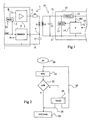
- FIG. 1 very schematically represents and simplified, a classic example of a data exchange system of the type to which the present invention relates between a terminal 1 read-write and a transponder 10.
- terminal 1 is essentially made up of a series oscillating circuit, formed of an inductance L1 in series with a capacitor C1 and a resistor R1, between a terminal 2 output of an antenna amplifier or coupler 3 and a terminal 4 to a reference potential (generally, the mass).
- the amplifier 3 receives a high frequency transmission signal E, from a modulator 5 (MOD1) which receives a reference frequency (OSC signal) for example, a quartz oscillator (not represented).
- the modulator 5 receives, if necessary, a signal Tx of data to be transmitted and, in the absence of data transmission from the terminal, delivers the high frequency carrier (for example, 13.56 MHz) suitable for remote powering a transponder.
- terminal 1 uses a demodulator 6 (DEMOD1) which is used to detect a load variation generated by the transponder 10 on the high frequency signal.
- the demodulator 6 takes, for example, the voltage at terminals 7 and 4 of capacitor C1, and delivers a Rx signal of data received after demodulation.
- circuits not shown generally equip A terminal 1.
- a control and operating circuit data received based, more often than not, on a microprocessor processing orders and data.
- These circuits communicate usually with different input / output circuits (keyboard, screen, means of exchange with a server, etc.) and / or processing not shown.
- Read-write terminal circuits draw the energy necessary for their operation from a supply circuit (not shown) connected, for example, to the electrical distribution network or batteries.
- a transponder 10 intended to cooperate with a terminal 1, essentially comprises a parallel oscillating circuit formed inductance L2 in parallel with a capacitor C2 between two input terminals 11 and 12 of a circuit 13 for controlling and treatment.
- Terminals 11 and 12 are, in practice, connected to the entry of a rectifying means (not shown) including outputs constitute DC power supply terminals internal to the transponder.
- These circuits generally include, essentially, a microprocessor 14 (P) capable of communicating with other elements (for example, a memory) by connections 15.
- the transponder 10 further comprises a demodulator 16 (DEMOD2) signals received from terminal 1 which delivers a signal Rx 'at circuit 14, and a modulator 17 (MOD2) for transmitting, to the terminal, information Tx 'which it receives from circuit 14.
- DEMOD2 demodulator 16
- MOD2 modulator 17
- Oscillating circuits of the terminal and the transponder are generally tuned on the same frequency corresponding to the frequency of an excitation signal of the oscillating circuit of the thick headed.
- This high frequency signal (for example 13.56 MHz) is used only transmission carrier but also carrier remote power supply to the transponder (s) found in the terminal field.
- a 10 transponder finds in the field of a terminal 1 a high frequency voltage is generated at terminals 11 and 12 of its resonant circuit.
- This tension after rectification and possible capping, is intended to supply the supply voltage of the electronic circuits 13 of the transponder. For reasons of clarity, the means of straightening, capping, and supplying power not shown in Figure 1.
- the demodulation takes place upstream of the clipping means to preserve the modulation of the amplitude data on the high frequency carrier transmitted by the terminal.
- This modulation amplitude is performed using different coding techniques in order to transmit data and / or commands to the transponders.
- the Tx 'data transmission from the transponder towards a terminal is generally carried out by modulating the load constituted by the resonant circuit L2, C2. This is why the modulator 17 has been shown in parallel on this resonant circuit.
- the charge variation is carried out at the rate of a sub carrier, called retromodulation, of frequency (for example 847.5 kHz) lower than that of the carrier.
- the load variation from a transponder can then be detected by the terminal as a variation amplitude or phase variation using, for example, a measurement of the voltage across the capacitor C1 or the current in the oscillating circuit using the demodulator 6.
- a problem that arises in transponder systems classic electromagnetic is that sometimes a transponder remotely powered by a terminal and transmitting data to destination of it is not detected by the terminal, that is to say the terminal demodulator does not reach detect the presence of data modulation.
- This phenomenon is generally referred to as the "demodulation hole”. For a given system, it is a relative position of a terminal and a transponder to which the terminal demodulator is "blind".
- demodulation hole is different from what we call "remote feeding hole” where it is the transponder which fails to be powered by the high frequency signal even while it is in the field electromagnetic terminal. Indeed, there is a position relative between a transponder and a terminal to which coupling magnetic between the oscillating circuits is such that the transponder is not supplied, i.e. the voltage recovered at terminals 11 and 12 of its oscillating circuit is too weak for it to work.
- the transponder is correctly supplied. It generally detects correctly the data transmitted by the terminal in modulation amplitude. It correctly transmits data to the terminal in retromodulation, by variation of the load of its circuit oscillating. However, the terminal's demodulator does not detect this retromodulation.
- This demodulation hole problem causes a terminal may not detect a transponder present in its field in the extent to which this detection conventionally uses the result of the terminal side data demodulator.
- a terminal when is in a standby state awaiting transmission, a terminal periodically issues interrogation requests in modulating the amplitude of the remote power carrier. Terminal then monitors the output of its receiver which will tell it the presence of a transponder. Indeed, when a transponder is finds "awakened” by its entry in the field of a terminal, this demodulates the interrogation message transmitted periodically by this terminal and responds to it to be identified.
- the output voltage of the demodulator is canceled, that is to say that one is in the presence of a hole of demodulation in two carrier frequency configurations (13.56 MHz) which, for a given coupling coefficient between the oscillating circuits of the terminal and the transponder concerned, frame the resonant frequency of the oscillating circuit L2-C2 of the transponder.
- this median frequency corresponds to the perfect match between the terminal and the transponder on the frequency of the remote feed carrier, where the amplitude available for demodulation is maximum.
- the position of the demodulation holes in the amplitude demodulator response varies depending on the mutual inductance between the oscillating circuits.
- this mutual inductance depends on the distance between the antennas L1 and L2 of the terminal and the transponder, therefore of the position relative of the transponder to the terminal during transmission.
- the output voltage of the demodulator is canceled, that is to say that we are in the presence of a demodulation hole in a frequency configuration which, for a coefficient of given coupling between the oscillating circuits of the terminal and the transponder concerned, corresponds to the perfect match of the terminal and the transponder on the frequency of the remote feed carrier. Transponder side, this frequency is then the frequency resonance of the L2-C2 oscillating circuit of the transponder.
- phase demodulation a notable drawback of conventional systems phase demodulation, is that we are forced to perform a compromise between remote power supply and demodulation capacity phase through the terminal. In addition, this compromise is delicate to realize, the position of the hole in the response of the demodulator of phase varying according to the mutual inductance between the oscillating circuits.
- the present invention aims to overcome the drawbacks conventional systems relating to the presence of demodulation holes in the response of the demodulator of a read-write terminal.
- the present invention aims to propose a new control method which makes a terminal read-write insensitive to data demodulation holes that it receives from a transponder entered in its field.
- the present invention also aims to provide a new terminal insensitive to data demodulation holes that it receives from a transponder entered in its field.
- the present invention also aims to provide a solution resulting in no modification of the transponders and which is therefore compatible with existing transponders.
- the present invention provides a method for controlling a generation terminal of a field electromagnetic by means of a circuit excitation signal oscillating, provided with means for regulating the signal phase in the oscillating circuit, consisting in comparing values currents of quantities linked to the current in the oscillating circuit and the voltage across its terminals with respect to predetermined values, in order to detect the presence of a transponder in the electromagnetic field.
- said predetermined values are measured and stored during no-load operation of the terminal, while no transponder is not present in its field.
- said presence detection is implemented when a demodulator that the terminal has does not detect any signal emitted by a transponder.
- the method consists, in the presence of a transponder detected, to deactivate the phase regulation, and to force the part imaginary of the impedance of the oscillating circuit from the terminal to a predetermined value.
- the forcing of said imaginary part is carried out by forcing the value of a variable capacitive element of the oscillating circuit.
- the predetermined forcing value of said imaginary part corresponds to an empty operation of the terminal.
- the predetermined forcing value of said imaginary part is function of the position of this imaginary part with respect to a limit value corresponding to an idle operation of the thick headed.
- the method consists, in the presence of a transponder detected and in the absence of data detection by a active demodulator among an amplitude demodulator and a demodulator phase of the terminal, select the other demodulator to detect data.
- the present invention also provides a terminal generation of an electromagnetic field suitable for cooperating with minus a transponder when the latter enters this field, and comprising means for implementing the method of the invention.
- a feature of the present invention is provide for direct determination of the presence of a transponder in the field of a read-write terminal, i.e. without the need to interpret demodulated signals from transmission of data from this transponder. More precisely, the present invention provides, in the absence of a signal demodulated usable by the terminal, to validate the absence of a transponder within the scope thereof by another determination independent of the existence of data transmission.
- Another feature of the present invention is to provide, in case of inconsistency between the result of the receiver and direct determination, corrective action allowing the terminal demodulator to interpret correctly the data received.
- This corrective action is preferably carried out on the terminal's oscillating circuit and, from preferably on the capacitive element of this circuit.
- the determination of the presence or absence of a transponder in the terminal field is carried out, according to the invention, by measuring the current in the oscillating circuit of the terminal and the voltage across its capacitive element (or quantities directly related to current and voltage), and comparing the current values obtained with stored values previously.
- the latter preferably correspond to values measured in a learning phase where the reader is in a particular configuration.
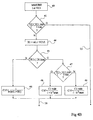
- Figure 2 is a simplified flowchart of a mode of implementation of a validation sequence for the presence of a transponder in the terminal field, applied to the state of standby of a read-write terminal.
- a transponder read-write terminal starts (block 20, ST), after an ignition, initialization and test phase, a watch procedure during which it waits for the establishment communication with a transponder.
- This procedure consists, essentially, of sending (block 21) periodically a interrogation sequence (REQ) for the transponder (s) possible in the terminal field.
- the reader monitors (block 22) the reception, by its receiver, of a response message (ACK) from a transponder entered in its field.
- the reader will loop on sending of a query 21.
- the reader When it receives an ACK response, it enters a verification mode that the transponder is correct a transponder intended for it, as well as in a mode possible anti-collision (block 23, INIT / COM) to individualize several transponders possibly present in the field.
- a verification mode that the transponder is correct a transponder intended for it, as well as in a mode possible anti-collision (block 23, INIT / COM) to individualize several transponders possibly present in the field.
- INIT / COM mode possible anti-collision
- the reader in response to a query request by a terminal, if several transponders are present in the field thereof, they can respond at the same time or with a time difference low enough to make the demodulation result by the unusable reader. This must then either select a transponder with which he wants to communicate, either assign different channels to different transponders.
- the terminal uses the results provided by its receiver.
- the values of these elements can also vary from a transponder to the other, provision is made according to the present invention to regulate the phase of the terminal's oscillating circuit with respect to a value reference.
- this phase regulation is performed by means of a loop whose response time is chosen so that the loop is slow enough so as not to hinder possible retromodulation from a transponder, and be fast enough before the speed of passage of a transponder in the terminal field.
- modulation frequencies by example, the frequency of the remote feed carrier of 13.56 MHz, and the retromodulation frequency of 847.5 kHz used in the data transmission from the transponder to the thick headed.
- phase control of the oscillating circuit of the terminal can be implemented using known means such as those described, for example, in the patent application European No. 0 857 981 already cited. Adaptation of the planned system by this document for the implementation of the invention, or of a another known phase control system, is within the range of the skilled person from the functional indications given in this description.
- the excitation voltage of the oscillating circuit is proportional by a coefficient constant at the voltage (VC1) across the capacitive element of terminal. Therefore, assess the apparent impedance of the circuit oscillating from the terminal amounts to assessing the relationship between the voltage across the capacitive element and the current in the oscillating circuit.
- the evaluation of the presence of a transponder carried out by the invention exclusively uses current information in the terminal oscillating circuit and voltage across the terminals this one, more precisely at the limits of its capacitive element (or information directly linked, by coefficients invariable and determined, at these magnitudes).
- the values known as "to empty ", current and voltage when no transponder is present in the terminal field are easily measurable on the read-write terminal side, for example, in a learning phase, for example, which follows the implementation of the terminal in its application site.
- Two embodiments of the invention corresponding to two corrective actions to undertake according to the type of demodulator of the read-write terminal.
- a first embodiment applied to a amplitude demodulation by the terminal will be described in relation with Figures 3A, 4A and 5A.
- FIG. 3A represents, schematically and simplified, a first embodiment of a read-write terminal according to the invention, equipped with a loop for regulating phase of the oscillating circuit and an amplitude demodulator.
- terminal 30 includes a circuit oscillating formed by an inductor or antenna L1, in series with a capacitive element 31 and a resistive element R1, between a terminal 32 output from an antenna amplifier or coupler 33 and a terminal 34 at a reference potential, (generally, ground).
- a measuring element 35 of the current in the oscillating circuit is interposed, for example, between the capacitive element 31 and the ground 34.
- This measurement element 35 is used, in particular, to deliver information of the current (I) intended for the operating means of the terminal side data, consisting for example of a microprocessor (not shown).
- the amplifier 33 receives a transmission signal E high frequency, from a modulator 36 (MOD1) which receives a reference frequency (OSC signal), for example, from a quartz oscillator (not shown).
- the modulator 36 receives, if necessary, a data signal Tx to be transmitted and, in the absence data transmission from the terminal, delivers the carrier high frequency (for example 13.56 MHz) suitable for remote supplying a transponder.
- the capacitive element 31 is a capacitive element variable and controllable by a CTRL signal.
- Phase regulation of the current is carried out in the antenna L1 with respect to a reference signal.
- This regulation is a high frequency signal regulation, that is to say of the carrier signal corresponding to signal E in the absence of data to be transmitted.
- This regulation is carried out in varying the capacity of the oscillating circuit of terminal 30 by so as to maintain the current in the antenna in phase relation constant with the reference signal which corresponds, for example, to the OSC signal supplied by the modulator oscillator.
- the regulation is slow enough not to take into account that the static phase variations in front of the subcarrier of retromodulation.
- the CTRL signal comes from a circuit 37 (COMP) whose role is to detect the phase deviation from the reference signal and modify the capacity accordingly of element 31.
- COMP circuit 37
- the phase measurement is made from a measurement of the current I in the circuit at by means of the current transformer 35 mounted in series with the element 31.
- This transformer generally consists of a primary winding 35 'between element 31 and earth, and of a secondary winding 35 "of which a first terminal is connected directly to earth 34 and a second terminal of which delivers a signal MES1 as a function of current I, sent to comparator 37 which consequently controls the capacitive element 31 by means of the signal CTRL.
- the signal MES1 is also sent, as previously indicated, to the microprocessor or analogous, to implement the validation method of the invention.
- a second measurement signal MES2 delivering a information on the voltage VC1 across the element capacitive 31, is also sent to the microprocessor. This signal is taken, for example, between the inductance L1 and the element 31.
- terminal 30 includes an amplitude demodulator 38 (DEMODA) receiving as input, for example, the voltage VC1 (or an image of the current) across the capacitive element 31 (more precisely, across the series association of this capacitive element 31 and intensity sensor 35), and outputting a signal Rx restoring a possible retromodulation of data received a transponder to the rest of the terminal's electronic circuits not shown.
- DEMODA amplitude demodulator 38
- FIG. 4A is a flow diagram of an implementation mode implementation of the validation method (block 24, FIG. 2) of the invention, applied to amplitude demodulation.
- the resistance R2 represents the equivalent resistance of all the circuits (micro
- the vacuum coefficient is zero insofar as the vacuum coupling is also zero.
- variable X2 is different from 0, i.e. its circuit oscillating is detuned even slightly. This is perfectly consistent with the fact that the transponder transmits data to destination of the terminal, i.e. it changes the charge that it constitutes on the terminal's oscillating circuit.
- the first case corresponds if no transponder is present in the field of the terminal.
- the correction made according to the invention to exit of a demodulation hole is preferably to force the value of the capacity C1 of the element 31 over a predetermined value during the learning phase.
- phase regulation is preferably carried out by a modification of the capacity of the oscillating circuit. Therefore, a variable capacitive element is provided for which the value, either to enslave the phase statically in the oscillating circuit, either to force the value of the capacitive element in order to shift the tuning of the circuit when we are in presence of a demodulation hole.
- the C1 capacity value is forced for example, by means of a COM signal delivered by the processor processing (not shown) to a circuit 39 for selecting the command to control element 31 between the CTRL signal delivered by circuit 37 and the forcing value.
- a COM signal delivered by the processor processing (not shown) to a circuit 39 for selecting the command to control element 31 between the CTRL signal delivered by circuit 37 and the forcing value.
- Practical realization of this function is within the reach of the skilled person.
- the phase regulator can be modified to be able to impose a different setpoint on it allowing the forced value of the capacity C1 is delivered by the signal CTRL.
- the capacity C1 of the element 31 of the oscillating circuit is forced (block 42) to a value C1 f equal to the empty value C1 that the latter had when empty.
- This value of the no-load capacity can easily be memorized in the learning phase where the no-load current and voltage have been measured.
- the initialization process ( Figure 2) continues (link 26) based on this new capacity value.
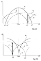
- FIG. 5A illustrates the first mode of implementation of the method of the invention by representing three examples of amplitudes variation of current I, available for the amplitude demodulator as a function of the C2 capacity of the transponder present in the terminal field. In other words, this illustrates the signal available to exploit a back modulation from a transponder using the demodulator amplitude.
- the variation of I corresponds, as a first approximation, the voltage variation dV across the element 31, and represents the signal to be detected by the amplitude demodulator 38. It is therefore a "dynamic" variation (at the rate of the retromodulation subcarrier, for example, 847.5 kHz).
- a first curve 50 drawn in solid lines corresponds to the ideal case where the imaginary part of the impedance X1 (formula 3) of the terminal's oscillating circuit is zero. This means that the terminal's oscillating circuit is perfectly tuned, including in its dynamic operation. This case is ideal insofar as the reader being provided with a phase loop, static with respect to the variations generated by the back modulation (for example, at 847 kHz), the apparent value X1 app is statically zero (formula 2). It will be remembered that the primary purpose of the static phase loop is to optimize the tuning as a function of the load of the transponder in order to obtain an optimal range of remote supply thereof.
- the shape 50 forms a kind of bell centered on the value C2 acc of the capacity of a transponder perfectly tuned on the remote supply carrier.
- the implementation of the correction provided by the invention corresponds to moving the operating point of the reader to the ideal curve (pace 50). This action is symbolized by a double arrow 57 at the point 53 taken as an example.
- the capacitive element 31 of variable capacity consists of a diode or a transistor, the junction capacity of which is varied by modifying the voltage applied to its terminals, it can be considered that this voltage control corresponds to the voltage VC1.
- this voltage control corresponds to the voltage VC1.
- it is possible to store, in a learning phase, only the value of the no-load capacity as well as the no-load current. Then, as soon as a demodulation hole is detected, the element C1 is polarized to an empty value VC1 which is calculated by the following formula: VC1 empty I empty ⁇ C1 empty .
- FIGS. 3B, 4B and 5B A second embodiment of the invention applied to a phase demodulation by the terminal will be described below in relationship with FIGS. 3B, 4B and 5B which are to be compared with Figures 3A, 4A and 5A which have just been described.
- FIG. 3B represents an embodiment of a terminal 30 according to the present invention applied to demodulation phase with it.
- the difference between the terminal of the figure 3B and that of FIG. 3A is mainly linked to the demodulator used.
- a demodulator of phase (DEMODP) delivers the Rx signal from demodulated data to from an assessment of the phase shift at the rate of the retromodulation emitted by a transponder.
- the comparator 37 of the phase control loop uses the same phase detector than the one used to demodulate the signal from the transponder. Consequently, the signal Rx is delivered by the comparator 37. It will be remembered, however, that the interpretation of the result detection is different.
- the receiver takes into account dynamic variations (at the frequency of the subcarrier) while that the phase regulator takes account of static variations.
- the phase regulator takes account of static variations.
- two phase detectors separate.
- the rest of terminal 30 is similar to the constitution exposed in relation to FIG. 3A applied to the amplitude demodulation.
- FIG. 4B illustrates, by a flowchart, the correction applied according to the invention to the value of the element terminal capacitive in the presence of a demodulation hole of phase.
- Blocks 40 and 41 are similar to those exposed in relationship to Figure 4A.
- force the value of capacity C1 to its value at vacuum would amount to forcing the tuning of the oscillating circuit of the terminal on the carrier frequency.
- FIG. 5B represents three examples of appearance of variation d ⁇ of the phase in the oscillating circuit of the terminal in function of the value taken by the capacity C2 of the circuit oscillating from the transponder.
- Figure 5B is close to the FIG. 5A applied to the amplitude modulation.
- a first curve 60 drawn in solid lines corresponds in the ideal case where the imaginary part of the impedance X1 (formula 3) the oscillating circuit of the terminal is zero. Like before, this corresponds to the ideal case of a perfect chord of the thick headed.
- the pace 60 increases in a hyperbolic fashion, symmetrically on either side of a minimum 65 at the value C2 acc of the capacity of a transponder perfectly tuned on the remote supply carrier and which, in phase demodulation, corresponds to a demodulation hole.
- the zero crossing 65 of the curve 60 representing the ideal case corresponds to a capacity value C2 included in tolerance and drift ranges.
- the invention proposes a new analysis of the behavior of the oscillating circuits of a terminal and a transponder to determine, always from calculated values in a learning phase and a comparison by compared to current values, the correction to be made.
- the invention plans to force a value of X1 of opposite sign and large enough to deviate from the "theoretical" or “ideal” agreement 65. This amounts to passing on another curve of which not only the minimum is separated from the current minimum through point 65, but whose impedance value apparent is also different. So we have to accept here a reduction in the remote supply of the transponder. We seeks, however, to ensure that this drop is minimal.
- a force value C1 f must be provided which can be easily determined by calculation from stored and measured values.
- X1 we can force the value of k to k max to put in the same conditions as those of a transponder with maximum coupling where we know that we are out of a demodulation hole
- the coefficient k max is, approximately but sufficiently, known for a given family of transponders for which the terminal in question is intended. It is generally between approximately 0.1 and 0.4.
- the dynamic phase shift d ⁇ can be measured, either on current I, or on voltage VC1 or similar. Consequently, the invention also applies to the case where other means than an intensity sensor are used to detect the phase shift. It depends on the type of receiver phase used.
- FIG. 6 represents, schematically and simplified, a third embodiment of the present invention applied to a read-write terminal 70 provided, for the demodulation of the signals coming from a retromodulation by a transponder, both of a phase demodulator (DEMODP) and an amplitude demodulator (DEMODA).
- DEMODP phase demodulator
- DEMODA amplitude demodulator
- the interpretation of the existence of a transponder in the terminal field is then used, not to modify the capacity of the variable element of the terminal's oscillating circuit, but to select the demodulator to use to extract the signal Rx .
- the demodulation holes do not have the same positions (in terms of the capacitance C2) depending on whether the terminal demodulates in amplitude or in phase.
- the demodulator of the opposite type is not "blind” insofar as the change of demodulator does not modify the imaginary part X1 app of the apparent impedance.
- changing the demodulator when one is in a hole, for example 53 or 54 amounts to placing oneself on the curve 61, respectively 62, for the same capacity value C2.
- Terminal 70 includes the same elements as those common to terminals 30 of Figures 3A and 3B with the exception of circuit 39. It further comprises an amplitude demodulator 38 connected as in Figure 3A and a phase demodulator, preferably similar to that of Figure 3B.
- a circuit 71 of selection receives the respective outputs 72 and 73 from the demodulators amplitude and phase and delivers the signal Rx to destination of the processing processor (not shown).
- the circuit 71 is controlled by a two-state COM signal from the processing processor and obtained, preferably, in a way similar to that of the embodiments described above.
- a priority demodulator that is to say selected, is determined in the absence of a demodulation hole.
- An advantage of the present invention is that by means of determination of easily measurable electrical quantities, the reliability of the operation of a electromagnetic transponder read-write terminal.
- Another advantage of the invention is that one intervenes than on the read-write terminal side. Therefore, the operation of the transponder present in the terminal field is not affected and the invention can be implemented with existing conventional transponders.
- Another advantage of the invention is that by choosing to intervene on the variable of adjustment of the static loop of phase regulation, structural modifications are minimized of the terminal.
- Another advantage of the present invention is that it makes the transponder system function insensitive to demodulation holes.
- Another advantage of the present invention is that the correction implemented does not harm the remote supply of the transponder.
- Another advantage of the present invention is that it does not require any adaptation according to the sensitivity of the demodulator. We can even consider that it adapts automatically to a variation of the demodulation threshold. Indeed, as the correction made by the invention is implemented from of the demodulation result, it is independent of the threshold of detection of the demodulator.
- the invention transposes in the case of a "capacitive" retromodulation which modifies the value of the capacitance C2 to the rhythm of the subcarrier.
- the holes demodulation are functions of resistance R2 and therefore vary depending on the consumption of the transponder circuits.
- the the detection principle described above is not changed in any way. We will simply adapt the correction on the terminal side.
Landscapes
- Engineering & Computer Science (AREA)
- Artificial Intelligence (AREA)
- Computer Vision & Pattern Recognition (AREA)
- Physics & Mathematics (AREA)
- General Physics & Mathematics (AREA)
- Theoretical Computer Science (AREA)
- Near-Field Transmission Systems (AREA)
- Radar Systems Or Details Thereof (AREA)
Applications Claiming Priority (2)
| Application Number | Priority Date | Filing Date | Title |
|---|---|---|---|
| FR0006071A FR2808946A1 (fr) | 2000-05-12 | 2000-05-12 | Validation de la presence d'un transpondeur electromagnetique dans le champ d'un lecteur |
| FR0006071 | 2000-05-12 |
Publications (2)
| Publication Number | Publication Date |
|---|---|
| EP1154366A1 true EP1154366A1 (de) | 2001-11-14 |
| EP1154366B1 EP1154366B1 (de) | 2011-03-30 |
Family
ID=8850152
Family Applications (1)
| Application Number | Title | Priority Date | Filing Date |
|---|---|---|---|
| EP01410049A Expired - Lifetime EP1154366B1 (de) | 2000-05-12 | 2001-05-11 | Präsenzbestätigung eines elektromagnetischen Transponders im Felde eines Lesers |
Country Status (5)
| Country | Link |
|---|---|
| US (1) | US7049936B2 (de) |
| EP (1) | EP1154366B1 (de) |
| JP (1) | JP4715025B2 (de) |
| DE (1) | DE60144309D1 (de) |
| FR (1) | FR2808946A1 (de) |
Cited By (1)
| Publication number | Priority date | Publication date | Assignee | Title |
|---|---|---|---|---|
| WO2008050951A1 (en) | 2006-10-23 | 2008-05-02 | Lg Innotek Co., Ltd | Rf sensor system and method for operating the same |
Families Citing this family (25)
| Publication number | Priority date | Publication date | Assignee | Title |
|---|---|---|---|---|
| FR2796781A1 (fr) * | 1999-07-20 | 2001-01-26 | St Microelectronics Sa | Dimensionnement d'un systeme a transpondeur electromagnetique pour un fonctionnement en hyperproximite |
| FR2808942B1 (fr) * | 2000-05-12 | 2002-08-16 | St Microelectronics Sa | Validation de la presence d'un transpondeur electromagnetique dans le champ d'un lecteur a demodulation de phase |
| US8638196B2 (en) * | 2002-02-01 | 2014-01-28 | Nxp B.V. | Adapting coil voltage of a tag to field strength |
| FR2840742A1 (fr) * | 2002-06-06 | 2003-12-12 | St Microelectronics Sa | Lecteur de transpondeur electromagnetique |
| EP1667336B1 (de) * | 2003-09-19 | 2013-05-01 | Brother Kogyo Kabushiki Kaisha | Funk-etiketten-leser/-schreiber |
| EP1610257A1 (de) * | 2004-06-23 | 2005-12-28 | St Microelectronics S.A. | Impedanzanpassung in einem Gerät zum Lesen elektromagnetischer Transpondern |
| WO2006011208A1 (ja) * | 2004-07-29 | 2006-02-02 | Mitsubishi Denki Kabushiki Kaisha | 無線通信制御装置および無線通信システム |
| DE102004062364A1 (de) * | 2004-12-13 | 2006-06-14 | Atmel Germany Gmbh | Verfahren zur drahtlosen Datenübertragung |
| US7826873B2 (en) * | 2006-06-08 | 2010-11-02 | Flextronics Ap, Llc | Contactless energy transmission converter |
| US8609978B2 (en) * | 2007-02-14 | 2013-12-17 | Flextronics Ap, Llc | Leadframe based photo voltaic electronic assembly |
| JP2009271775A (ja) * | 2008-05-08 | 2009-11-19 | Toshiba Corp | 受信装置 |
| JP5282498B2 (ja) * | 2008-09-12 | 2013-09-04 | ソニー株式会社 | リーダ/ライタ、通信方法、およびプログラム |
| FR2947075A1 (fr) | 2009-06-19 | 2010-12-24 | St Microelectronics Rousset | Evaluation resistive du facteur de couplage d'un transpondeur electromagnetique |
| FR2947073A1 (fr) * | 2009-06-19 | 2010-12-24 | St Microelectronics Rousset | Gestion d'energie dans un transpondeur electromagnetique |
| FR2947074A1 (fr) * | 2009-06-19 | 2010-12-24 | St Microelectronics Rousset | Evaluation inductive du facteur de couplage d'un transpondeur electromagnetique |
| FR2947362A1 (fr) | 2009-06-25 | 2010-12-31 | St Microelectronics Sas | Authentification d'un terminal par un transpondeur electromagnetique |
| FR2947364A1 (fr) * | 2009-06-25 | 2010-12-31 | St Microelectronics Sas | Authentification d'un couple terminal-transpondeur electromagnetique par le terminal |
| US8362902B2 (en) * | 2009-07-24 | 2013-01-29 | Electronics And Telecommunications Research Institute | RFID reader and method for identifying RFID tag thereof and apparatus for analyzing reception power pattern |
| DE102010006230A1 (de) * | 2010-01-28 | 2011-08-18 | JUNGHANS Microtec GmbH, 78655 | Elektronische Schaltung und Verfahren zur Bestimmung der Impedanz |
| FR2960993A1 (fr) * | 2010-06-03 | 2011-12-09 | St Microelectronics Rousset | Evaluation du facteur de couplage d'un transpondeur electromagnetique par desaccord capacitif |
| FR2976104B1 (fr) | 2011-06-03 | 2013-11-15 | St Microelectronics Rousset | Securisation d'une communication entre un transpondeur electromagnetique et un terminal |
| FR2976102B1 (fr) | 2011-06-03 | 2013-05-17 | St Microelectronics Rousset | Assistance au positionnement d'un transpondeur |
| FR2976105B1 (fr) | 2011-06-03 | 2013-05-17 | St Microelectronics Rousset | Securisation d'une communication par un transpondeur electromagnetique |
| FR2976103B1 (fr) | 2011-06-03 | 2013-05-17 | St Microelectronics Rousset | Aide au positionnement d'un transpondeur |
| EP2662800B1 (de) * | 2012-05-07 | 2014-11-05 | ST-Ericsson SA | NFC-Leser mit konstantem Magnetfeld |
Citations (3)
| Publication number | Priority date | Publication date | Assignee | Title |
|---|---|---|---|---|
| EP0722094A1 (de) * | 1995-01-11 | 1996-07-17 | Sony Chemicals Corporation | Sende-Empfänger für kontaktloses IC-Kartensystem |
| EP0857981A1 (de) * | 1997-02-05 | 1998-08-12 | EM Microelectronic-Marin SA | Basisstation eines Fernabfragesystems mit spannungsgesteuertem und phasengeregeltem Oszillator |
| WO1999043096A1 (en) | 1998-02-19 | 1999-08-26 | Motorola Inc. | Data communications terminal and method of adjusting a power signal generated therefrom |
Family Cites Families (108)
| Publication number | Priority date | Publication date | Assignee | Title |
|---|---|---|---|---|
| GB579414A (en) | 1941-10-15 | 1946-08-02 | Standard Telephones Cables Ltd | Improvements in or relating to electric wave filters |
| US5202644A (en) | 1959-06-11 | 1993-04-13 | Ail Systems, Inc. | Receiver apparatus |
| US3618089A (en) | 1969-01-29 | 1971-11-02 | Moran Instr Corp | Range and time measure system |
| US4068232A (en) | 1976-02-12 | 1978-01-10 | Fairchild Industries, Inc. | Passive encoding microwave transponder |
| JPS53120295A (en) | 1977-03-30 | 1978-10-20 | Toshiba Corp | Subject discrimination device |
| DE2732543C3 (de) | 1977-07-19 | 1980-08-07 | Precitec Gesellschaft Fuer Praezisionstechnik Und Elektronik Mbh & Co Entwicklungs- Und Vertriebs-Kg, 7570 Baden-Baden | Vorrichtung zur Erfassung von sich im Gebiet einer Grenzfläche befindenden Objekten |
| DK146108C (da) | 1978-11-13 | 1983-11-21 | Medibit A S | Fremgangsmaade til overfoering af information samt anlaeg til udoevelse af fremgangsmaaden |
| US4278977A (en) | 1979-05-04 | 1981-07-14 | Rca Corporation | Range determining system |
| US4258348A (en) | 1979-11-13 | 1981-03-24 | Stb Transformer Company | Current measuring transformer |
| US4928108A (en) | 1983-12-20 | 1990-05-22 | Bsh Electronics, Ltd. | Electrical signal separating device having isolating and matching circuitry for split passband matching |
| US4673932A (en) * | 1983-12-29 | 1987-06-16 | Revlon, Inc. | Rapid inventory data acquistion system |
| US4593412A (en) | 1984-05-21 | 1986-06-03 | Multi-Elmac Company | Integrated oscillator antenna for low power, low harmonic radiation |
| US4706050A (en) | 1984-09-22 | 1987-11-10 | Smiths Industries Public Limited Company | Microstrip devices |
| US4656472A (en) | 1985-01-23 | 1987-04-07 | Walton Charles A | Proximity identification system with power aided identifier |
| JPS61196603A (ja) | 1985-02-26 | 1986-08-30 | Mitsubishi Electric Corp | アンテナ |
| US4660192A (en) | 1985-04-11 | 1987-04-21 | Pomatto Sr Robert P | Simultaneous AM and FM transmitter and receiver |
| DE3707173A1 (de) | 1986-03-07 | 1987-09-10 | Iskra Sozd Elektro Indus | Schaltungsanordnung einer lesevorrichtung fuer elektromagnetische identifikationskarten |
| GB2197107B (en) | 1986-11-03 | 1990-12-12 | Mars Inc | Data-storing devices |
| IL82025A (en) | 1987-03-27 | 1993-07-08 | Galil Electro Ltd | Electronic data communications system |
| US4802080A (en) | 1988-03-18 | 1989-01-31 | American Telephone And Telegraph Company, At&T Information Systems | Power transfer circuit including a sympathetic resonator |
| US5701121A (en) | 1988-04-11 | 1997-12-23 | Uniscan Ltd. | Transducer and interrogator device |
| JP2612190B2 (ja) | 1988-08-31 | 1997-05-21 | 山武ハネウエル株式会社 | 応答装置と質問装置からなる全二重通信装置 |
| US5055853A (en) | 1988-10-03 | 1991-10-08 | Garnier Robert C | Magnetic frill generator |
| EP0369622A3 (de) | 1988-11-09 | 1991-04-17 | Security Tag Systems, Inc. | Nahlesen eines kodierten Etiketts |
| US5305008A (en) | 1991-08-12 | 1994-04-19 | Integrated Silicon Design Pty. Ltd. | Transponder system |
| US5084699A (en) * | 1989-05-26 | 1992-01-28 | Trovan Limited | Impedance matching coil assembly for an inductively coupled transponder |
| US5099227A (en) | 1989-07-18 | 1992-03-24 | Indala Corporation | Proximity detecting apparatus |
| US5126749A (en) | 1989-08-25 | 1992-06-30 | Kaltner George W | Individually fed multiloop antennas for electronic security systems |
| US5142292A (en) | 1991-08-05 | 1992-08-25 | Checkpoint Systems, Inc. | Coplanar multiple loop antenna for electronic article surveillance systems |
| US5235326A (en) * | 1991-08-15 | 1993-08-10 | Avid Corporation | Multi-mode identification system |
| US5214409A (en) | 1991-12-03 | 1993-05-25 | Avid Corporation | Multi-memory electronic identification tag |
| DE69308015D1 (de) | 1992-02-29 | 1997-03-20 | Scantronic Ltd | Stromversorgung, insbesondere für alarmsystem |
| SE469959B (sv) | 1992-03-06 | 1993-10-11 | Electrolux Ab | Anordning för överföring av styrkommandon i en med växelström driven apparat eller maskin |
| KR100251666B1 (ko) | 1992-04-29 | 2000-04-15 | 윌리엄 비. 켐플러 | 충전제어에의한무선주파수식별시스템 |
| US5452344A (en) | 1992-05-29 | 1995-09-19 | Datran Systems Corporation | Communication over power lines |
| NL9201270A (nl) | 1992-07-15 | 1994-02-01 | Nedap Nv | Antiwinkeldiefstal-antenne met draaiveld. |
| JP2747395B2 (ja) | 1992-07-20 | 1998-05-06 | 三菱電機株式会社 | 非接触icカード、非接触icカードリーダライタ及びデータ伝送方法 |
| NZ314270A (en) * | 1992-11-18 | 1998-06-26 | British Tech Group | Transponder identification system: interrogator transmits inhibiting signal to disable transponders |
| JP3003826B2 (ja) * | 1992-12-11 | 2000-01-31 | 三菱電機株式会社 | クロック再生回路 |
| DE4327642C2 (de) | 1993-05-17 | 1998-09-24 | Anatoli Stobbe | Lesegerät für ein Detektierplättchen |
| US5451958A (en) | 1993-05-21 | 1995-09-19 | Texas Instruments Deutschland Gmbh | Dual standard RF-ID system |
| US5850416A (en) | 1993-06-30 | 1998-12-15 | Lucent Technologies, Inc. | Wireless transmitter-receiver information device |
| US5324315A (en) | 1993-08-12 | 1994-06-28 | Medtronic, Inc. | Closed-loop downlink telemetry and method for implantable medical device |
| US5541604A (en) | 1993-09-03 | 1996-07-30 | Texas Instruments Deutschland Gmbh | Transponders, Interrogators, systems and methods for elimination of interrogator synchronization requirement |
| NL9301650A (nl) | 1993-09-24 | 1995-04-18 | Nedap Nv | Onafhankelijk antennestelsel voor detectiesystemen. |
| JPH085731A (ja) | 1993-10-04 | 1996-01-12 | Texas Instr Deutschland Gmbh | Rf−idトランスポンダの位置の決定 |
| US5521602A (en) | 1994-02-10 | 1996-05-28 | Racom Systems, Inc. | Communications system utilizing FSK/PSK modulation techniques |
| US5504485A (en) | 1994-07-21 | 1996-04-02 | Amtech Corporation | System for preventing reading of undesired RF signals |
| US5550536A (en) | 1994-08-17 | 1996-08-27 | Texas Instruments Deutschland Gmbh | Circuit frequency following technique transponder resonant |
| FR2724477B1 (fr) | 1994-09-13 | 1997-01-10 | Gemplus Card Int | Procede de fabrication de cartes sans contact |
| JPH0962816A (ja) | 1994-10-06 | 1997-03-07 | Mitsubishi Electric Corp | 非接触icカードおよびこれを含む非接触icカードシステム |
| JPH08123919A (ja) | 1994-10-28 | 1996-05-17 | Mitsubishi Electric Corp | 非接触icカードシステムおよびその通信方法 |
| GB9503352D0 (en) | 1995-02-21 | 1995-04-12 | Sinnett Glyn | Remote control system |
| US5691605A (en) | 1995-03-31 | 1997-11-25 | Philips Electronics North America | Electronic ballast with interface circuitry for multiple dimming inputs |
| US5604411A (en) | 1995-03-31 | 1997-02-18 | Philips Electronics North America Corporation | Electronic ballast having a triac dimming filter with preconditioner offset control |
| JPH095430A (ja) * | 1995-06-22 | 1997-01-10 | Fujitsu Ten Ltd | トランスポンダ用アンテナ駆動装置 |
| SE513690C2 (sv) | 1995-08-16 | 2000-10-23 | Alfa Laval Agri Ab | Antennsystem med drivkretsar för transponder |
| US6243013B1 (en) | 1999-01-08 | 2001-06-05 | Intermec Ip Corp. | Cascaded DC voltages of multiple antenna RF tag front-end circuits |
| JPH0981701A (ja) | 1995-09-19 | 1997-03-28 | Toshiba Corp | 非接触式情報記録媒体および非接触式情報伝送方法 |
| JPH09218263A (ja) | 1995-10-11 | 1997-08-19 | Texas Instr Inc <Ti> | トランスポンダ・システム及びその動作方法 |
| DE19541855C1 (de) | 1995-11-09 | 1997-02-20 | Siemens Ag | Diebstahlschutzsystem für ein Kraftfahrzeug |
| NL1001761C2 (nl) | 1995-11-28 | 1997-05-30 | Ronald Barend Van Santbrink | Stelsel voor contactloze data-uitwisseling tussen een lees- en schrijf- eenheid en één of meer informatiedragers. |
| SE506449C2 (sv) | 1996-02-12 | 1997-12-15 | Rso Corp | Artikelövervakningssystem |
| AUPO055296A0 (en) | 1996-06-19 | 1996-07-11 | Integrated Silicon Design Pty Ltd | Enhanced range transponder system |
| US6362737B1 (en) * | 1998-06-02 | 2002-03-26 | Rf Code, Inc. | Object Identification system with adaptive transceivers and methods of operation |
| JP3867251B2 (ja) | 1996-09-13 | 2007-01-10 | テミツク セミコンダクター ゲゼルシヤフト ミツト ベシユレンクテル ハフツング | 無線周波数識別システムにおいてデータを伝送する方法 |
| JPH10145267A (ja) | 1996-09-13 | 1998-05-29 | Hitachi Ltd | 高効率アンテナコイル並びに無線カードおよび無線カードを用いた情報通信システム |
| US6446049B1 (en) | 1996-10-25 | 2002-09-03 | Pole/Zero Corporation | Method and apparatus for transmitting a digital information signal and vending system incorporating same |
| WO1998020363A1 (en) | 1996-11-05 | 1998-05-14 | Philips Electronics N.V. | Contactless data transmission and receiving device with a synchronous demodulator |
| US6304169B1 (en) | 1997-01-02 | 2001-10-16 | C. W. Over Solutions, Inc. | Inductor-capacitor resonant circuits and improved methods of using same |
| JPH10203066A (ja) | 1997-01-28 | 1998-08-04 | Hitachi Ltd | 非接触icカード |
| TW376598B (en) | 1997-02-05 | 1999-12-11 | Em Microelectronic Marin Sa | Base station for a contactless interrogation system comprising a phase locked and voltage controlled oscillator |
| US5883582A (en) | 1997-02-07 | 1999-03-16 | Checkpoint Systems, Inc. | Anticollision protocol for reading multiple RFID tags |
| FR2760280B1 (fr) * | 1997-03-03 | 1999-05-21 | Innovatron Ind Sa | Procede de gestion des collisions dans un systeme d'echange de donnees sans contact |
| US6208235B1 (en) | 1997-03-24 | 2001-03-27 | Checkpoint Systems, Inc. | Apparatus for magnetically decoupling an RFID tag |
| JP3916291B2 (ja) * | 1997-03-28 | 2007-05-16 | ローム株式会社 | 情報通信装置 |
| JP3427668B2 (ja) | 1997-04-01 | 2003-07-22 | 株式会社村田製作所 | アンテナ装置 |
| JP3327324B2 (ja) * | 1997-04-16 | 2002-09-24 | 日本電信電話株式会社 | 非接触式icカードの故障判定方法および装置 |
| JP3792002B2 (ja) * | 1997-04-17 | 2006-06-28 | ローム株式会社 | データ通信装置、データ通信システムおよびデータ通信方法 |
| JPH1131913A (ja) | 1997-05-15 | 1999-02-02 | Murata Mfg Co Ltd | チップアンテナ及びそれを用いた移動体通信機 |
| JPH10322247A (ja) * | 1997-05-21 | 1998-12-04 | Mitsubishi Electric Corp | ワイヤレス伝送装置 |
| US6025780A (en) | 1997-07-25 | 2000-02-15 | Checkpoint Systems, Inc. | RFID tags which are virtually activated and/or deactivated and apparatus and methods of using same in an electronic security system |
| JPH1166248A (ja) | 1997-08-12 | 1999-03-09 | Mitsubishi Electric Corp | 非接触型icカード |
| US5986570A (en) | 1997-09-03 | 1999-11-16 | Micron Communications, Inc. | Method for resolving signal collisions between multiple RFID transponders in a field |
| JPH11177027A (ja) | 1997-09-15 | 1999-07-02 | Microchip Technol Inc | 集積回路半導体チップ及び誘導性コイルを含む片面パッケージ並びにその製造方法 |
| US6393045B1 (en) | 1997-09-26 | 2002-05-21 | Wherenet Corp. | Spread spectrum baseband modulation of magnetic fields for communications and proximity sensing |
| GB9727042D0 (en) | 1997-12-22 | 1998-02-18 | Advanced Technology Communicat | Tag and detection system |
| US6100788A (en) | 1997-12-29 | 2000-08-08 | Storage Technology Corporation | Multifunctional electromagnetic transponder device and method for performing same |
| US6281794B1 (en) | 1998-01-02 | 2001-08-28 | Intermec Ip Corp. | Radio frequency transponder with improved read distance |
| TW386617U (en) | 1998-02-23 | 2000-04-01 | Kye Systems Corp | High frequency wireless pointer apparatus |
| WO2000002236A2 (en) * | 1998-07-07 | 2000-01-13 | Memc Electronic Materials, Inc. | Radio frequency identification system and method for tracking silicon wafers |
| FR2781587B1 (fr) | 1998-07-21 | 2000-09-08 | Dassault Electronique | Lecteur perfectionne pour badges sans contact |
| US5955950A (en) | 1998-07-24 | 1999-09-21 | Checkpoint Systems, Inc. | Low noise signal generator for use with an RFID system |
| US6072383A (en) | 1998-11-04 | 2000-06-06 | Checkpoint Systems, Inc. | RFID tag having parallel resonant circuit for magnetically decoupling tag from its environment |
| US6424820B1 (en) | 1999-04-02 | 2002-07-23 | Interval Research Corporation | Inductively coupled wireless system and method |
| FR2792132B1 (fr) * | 1999-04-07 | 2001-11-02 | St Microelectronics Sa | Borne de lecture d'un transpondeur electromagnetique fonctionnant en couplage tres proche |
| US6650226B1 (en) * | 1999-04-07 | 2003-11-18 | Stmicroelectronics S.A. | Detection, by an electromagnetic transponder reader, of the distance separating it from a transponder |
| FR2792135B1 (fr) * | 1999-04-07 | 2001-11-02 | St Microelectronics Sa | Fonctionnement en complage tres proche d'un systeme a transpondeur electromagnetique |
| US6307468B1 (en) | 1999-07-20 | 2001-10-23 | Avid Identification Systems, Inc. | Impedance matching network and multidimensional electromagnetic field coil for a transponder interrogator |
| US6335665B1 (en) * | 1999-09-28 | 2002-01-01 | Lucent Technologies Inc. | Adjustable phase and delay shift element |
| US6650227B1 (en) * | 1999-12-08 | 2003-11-18 | Hid Corporation | Reader for a radio frequency identification system having automatic tuning capability |
| JP2001236474A (ja) * | 1999-12-16 | 2001-08-31 | Takamisawa Cybernetics Co Ltd | カードリードライト装置及びその制御方法とゲートシステム |
| US6617962B1 (en) * | 2000-01-06 | 2003-09-09 | Samsys Technologies Inc. | System for multi-standard RFID tags |
| FR2808941B1 (fr) * | 2000-05-12 | 2002-08-16 | St Microelectronics Sa | Validation de la presence d'un transpondeur electromagnetique dans le champ d'un lecteur a demodulation d'amplitude |
| US6307517B1 (en) | 2000-06-13 | 2001-10-23 | Applied Wireless Identifications Group, Inc. | Metal compensated radio frequency identification reader |
| US6229443B1 (en) | 2000-06-23 | 2001-05-08 | Single Chip Systems | Apparatus and method for detuning of RFID tag to regulate voltage |
| DE10163633A1 (de) * | 2001-12-21 | 2003-07-10 | Philips Intellectual Property | Stromquellenschaltung |
| FR2840742A1 (fr) * | 2002-06-06 | 2003-12-12 | St Microelectronics Sa | Lecteur de transpondeur electromagnetique |
-
2000
- 2000-05-12 FR FR0006071A patent/FR2808946A1/fr active Pending
-
2001
- 2001-05-10 JP JP2001140159A patent/JP4715025B2/ja not_active Expired - Lifetime
- 2001-05-11 US US09/853,891 patent/US7049936B2/en not_active Expired - Lifetime
- 2001-05-11 DE DE60144309T patent/DE60144309D1/de not_active Expired - Lifetime
- 2001-05-11 EP EP01410049A patent/EP1154366B1/de not_active Expired - Lifetime
Patent Citations (3)
| Publication number | Priority date | Publication date | Assignee | Title |
|---|---|---|---|---|
| EP0722094A1 (de) * | 1995-01-11 | 1996-07-17 | Sony Chemicals Corporation | Sende-Empfänger für kontaktloses IC-Kartensystem |
| EP0857981A1 (de) * | 1997-02-05 | 1998-08-12 | EM Microelectronic-Marin SA | Basisstation eines Fernabfragesystems mit spannungsgesteuertem und phasengeregeltem Oszillator |
| WO1999043096A1 (en) | 1998-02-19 | 1999-08-26 | Motorola Inc. | Data communications terminal and method of adjusting a power signal generated therefrom |
Cited By (3)
| Publication number | Priority date | Publication date | Assignee | Title |
|---|---|---|---|---|
| WO2008050951A1 (en) | 2006-10-23 | 2008-05-02 | Lg Innotek Co., Ltd | Rf sensor system and method for operating the same |
| EP2052352A4 (de) * | 2006-10-23 | 2011-04-20 | Lg Innotek Co Ltd | Hf-sensorsystem und betriebsverfahren dafür |
| US8103222B2 (en) | 2006-10-23 | 2012-01-24 | Lg Innotek Co., Ltd. | RF sensor system and method for operating the same |
Also Published As
| Publication number | Publication date |
|---|---|
| US7049936B2 (en) | 2006-05-23 |
| US20020011922A1 (en) | 2002-01-31 |
| EP1154366B1 (de) | 2011-03-30 |
| DE60144309D1 (de) | 2011-05-12 |
| JP4715025B2 (ja) | 2011-07-06 |
| FR2808946A1 (fr) | 2001-11-16 |
| JP2002033680A (ja) | 2002-01-31 |
Similar Documents
| Publication | Publication Date | Title |
|---|---|---|
| EP1154366B1 (de) | Präsenzbestätigung eines elektromagnetischen Transponders im Felde eines Lesers | |
| EP1154367B1 (de) | Vorhandenseinbestätigung eines elektromagnetischen Transponders in dem Feld eines Phasendemodulation-Lesers | |
| EP1164534B1 (de) | Überprüfung der Anvesenheit eines elektromagnetischen Transponders in dem Feld eines AM Lesers | |
| EP1043677B1 (de) | Ein mit sehr naher Koppelung arbeitendes Lesegerät für elektromagnetische Transponder | |
| EP2267643B1 (de) | Widerstandsbewertung des Kopplungsfaktors eines Elektromagnetischen Transponders | |
| EP1134690B1 (de) | Sendeleistungsanpassung in einem Leser für elektromagnetische Transponder | |
| EP2267642B1 (de) | Induktive Einschätzung des Kopplungsfaktors eines elektromagnetischen Transponders | |
| EP2267644B1 (de) | Energiesteuerung in einem elektromagnetischen Transponder | |
| EP2267647B1 (de) | Authentifizierung eines Endgeräts durch einen elektromagnetischen Transponder | |
| EP2267645B1 (de) | Authentifizierung eines elektromagnetischen Transponder-Endelements durch einen Transponder | |
| EP2267635B1 (de) | Authentifizierung eines elektromagnetischen Transponder-Endelements durch das Endelement | |
| FR2960993A1 (fr) | Evaluation du facteur de couplage d'un transpondeur electromagnetique par desaccord capacitif | |
| EP2114019B1 (de) | Wiederaufladung eines aktiven Transponders | |
| EP1043679B1 (de) | Leser mit Einrichtung zur Bestimmung des Abstandes zwischen dem Leser und einem Transponder | |
| EP2715615B1 (de) | Transponderpositionierhilfe | |
| WO2012164178A1 (fr) | Assistance au positionnement d'un transpondeur | |
| EP1154368A1 (de) | Lesegerät mit Mitteln zur Bestimmung der Anzahl von elektromagnetischen Transpondern im Felde des Lesegerätes | |
| FR2976104A1 (fr) | Securisation d'une communication entre un transpondeur electromagnetique et un terminal | |
| EP2715618B1 (de) | Herstellung einer sicheren kommunikation durch einen elektromagnetischen transponder |
Legal Events
| Date | Code | Title | Description |
|---|---|---|---|
| PUAI | Public reference made under article 153(3) epc to a published international application that has entered the european phase |
Free format text: ORIGINAL CODE: 0009012 |
|
| AK | Designated contracting states |
Kind code of ref document: A1 Designated state(s): AT BE CH CY DE DK ES FI FR GB GR IE IT LI LU MC NL PT SE TR Kind code of ref document: A1 Designated state(s): DE FR GB IT |
|
| AX | Request for extension of the european patent |
Free format text: AL;LT;LV;MK;RO;SI |
|
| 17P | Request for examination filed |
Effective date: 20020506 |
|
| AKX | Designation fees paid |
Free format text: DE FR GB IT |
|
| 17Q | First examination report despatched |
Effective date: 20080915 |
|
| GRAP | Despatch of communication of intention to grant a patent |
Free format text: ORIGINAL CODE: EPIDOSNIGR1 |
|
| RIN1 | Information on inventor provided before grant (corrected) |
Inventor name: WUIDART, LUC |
|
| GRAS | Grant fee paid |
Free format text: ORIGINAL CODE: EPIDOSNIGR3 |
|
| GRAA | (expected) grant |
Free format text: ORIGINAL CODE: 0009210 |
|
| AK | Designated contracting states |
Kind code of ref document: B1 Designated state(s): DE FR GB IT |
|
| REG | Reference to a national code |
Ref country code: GB Ref legal event code: FG4D Free format text: NOT ENGLISH |
|
| REF | Corresponds to: |
Ref document number: 60144309 Country of ref document: DE Date of ref document: 20110512 Kind code of ref document: P |
|
| REG | Reference to a national code |
Ref country code: DE Ref legal event code: R096 Ref document number: 60144309 Country of ref document: DE Effective date: 20110512 |
|
| PLBE | No opposition filed within time limit |
Free format text: ORIGINAL CODE: 0009261 |
|
| STAA | Information on the status of an ep patent application or granted ep patent |
Free format text: STATUS: NO OPPOSITION FILED WITHIN TIME LIMIT |
|
| 26N | No opposition filed |
Effective date: 20120102 |
|
| REG | Reference to a national code |
Ref country code: DE Ref legal event code: R097 Ref document number: 60144309 Country of ref document: DE Effective date: 20120102 |
|
| PGFP | Annual fee paid to national office [announced via postgrant information from national office to epo] |
Ref country code: IT Payment date: 20120421 Year of fee payment: 12 |
|
| PGFP | Annual fee paid to national office [announced via postgrant information from national office to epo] |
Ref country code: GB Payment date: 20130424 Year of fee payment: 13 |
|
| PG25 | Lapsed in a contracting state [announced via postgrant information from national office to epo] |
Ref country code: IT Free format text: LAPSE BECAUSE OF NON-PAYMENT OF DUE FEES Effective date: 20130511 |
|
| GBPC | Gb: european patent ceased through non-payment of renewal fee |
Effective date: 20140511 |
|
| PG25 | Lapsed in a contracting state [announced via postgrant information from national office to epo] |
Ref country code: GB Free format text: LAPSE BECAUSE OF NON-PAYMENT OF DUE FEES Effective date: 20140511 |
|
| REG | Reference to a national code |
Ref country code: FR Ref legal event code: PLFP Year of fee payment: 16 |
|
| REG | Reference to a national code |
Ref country code: FR Ref legal event code: PLFP Year of fee payment: 17 |
|
| REG | Reference to a national code |
Ref country code: FR Ref legal event code: PLFP Year of fee payment: 18 |
|
| PGFP | Annual fee paid to national office [announced via postgrant information from national office to epo] |
Ref country code: FR Payment date: 20200422 Year of fee payment: 20 Ref country code: DE Payment date: 20200421 Year of fee payment: 20 |
|
| REG | Reference to a national code |
Ref country code: DE Ref legal event code: R071 Ref document number: 60144309 Country of ref document: DE |