EP1155643A2 - Dispositif de support - Google Patents
Dispositif de support Download PDFInfo
- Publication number
- EP1155643A2 EP1155643A2 EP01111560A EP01111560A EP1155643A2 EP 1155643 A2 EP1155643 A2 EP 1155643A2 EP 01111560 A EP01111560 A EP 01111560A EP 01111560 A EP01111560 A EP 01111560A EP 1155643 A2 EP1155643 A2 EP 1155643A2
- Authority
- EP
- European Patent Office
- Prior art keywords
- elements
- spring
- adjusting
- adjustment
- individual
- Prior art date
- Legal status (The legal status is an assumption and is not a legal conclusion. Google has not performed a legal analysis and makes no representation as to the accuracy of the status listed.)
- Granted
Links
Images


Classifications
-
- A—HUMAN NECESSITIES
- A47—FURNITURE; DOMESTIC ARTICLES OR APPLIANCES; COFFEE MILLS; SPICE MILLS; SUCTION CLEANERS IN GENERAL
- A47C—CHAIRS; SOFAS; BEDS
- A47C23/00—Spring mattresses with rigid frame or forming part of the bedstead, e.g. box springs; Divan bases; Slatted bed bases
- A47C23/002—Spring mattresses with rigid frame or forming part of the bedstead, e.g. box springs; Divan bases; Slatted bed bases with separate resilient support elements, e.g. elastomeric springs arranged in a two-dimensional matrix pattern
Definitions
- the present invention relates to a support device, in particular Mattress, cushion element or spring base therefor, with several at least provided in a region of the support device Single support elements that have an almost punctual resolution of the Cause support surface in terms of their spring property, and several, at least part of the individual support elements, optionally activatable adjustment elements for adjusting the spring properties, in particular the spring hardness and / or the spring travel of the individual support elements.
- Such individual support elements are used for spring mattresses and upholstered furniture known for a long time. But also with spring frames for mattresses have been such individual support elements instead of the conventional for some time Slats used. Especially in the shoulder and pelvic area can be immersed deeper through the selective support and so that an improvement in lying comfort can be achieved.
- spring frames also have individual support elements an adjustment option for individual adjustment the spring properties desirable.
- the individual support elements Interchangeable design, so that for example a softer single support element can be exchanged for a harder one can and vice versa.
- individual support elements to provide elements with an open form that are inserted into this form can and thus the spring travel or the spring hardness of the individual support element change.
- clip-in clamping devices there are also individual support elements known with clip-in clamping devices.
- the invention has for its object the adjustment of To improve support devices of the type mentioned. In particular, should individual adaptation can be facilitated.
- the Handling simplified. Two or more adjustment elements can be used be activated together, for example by the individual support elements in a certain area of the support surface, the uniform requirements subject to be adjusted together. This eliminates one Individual setting to the same values among each other and it is guaranteed that in such an area they are actually always the same Values can be set.
- the adjustment elements can be used in support devices Single support elements, which are arranged in columns and rows, or columns can be activated together line by line. This will be an adjustment option created that like conventional slatted frames on one Line acts across the entire width of the support surface.
- the adjustment function is not only easier for the user to carry out, but also from the effect also easier to grasp, since it is based on previous experience matches with slatted frames.
- Activation device can be activated together. This allows advantageously entire areas of the support surface individually at the same time be adjusted. For example, the shoulder and / or the Pelvic area with two or more rows of individual support elements be individually adjustable together.
- the adjustment elements can be permanently installed in the support device and can be activated quickly and easily. But you can too be designed to be activated for activation only in the support device. This makes it possible, for example, to create the adjustment elements can be used at various locations on the support surface bring to.
- the spring travel and / or spring hardness can be configured be gradually adjustable according to the invention. With just two steps created an effective and easy-to-use adjustment option become.
- the spring travel and / or spring hardness continuously adjustable over at least one area. This creates a particularly high variability in spring properties created. Nevertheless, the adjustment device remains due to the common adjustability of the individual support elements easy to handle.
- One way to change the spring properties is the adjusting elements for adjusting the spring hardness and / or the spring travel as an adjustment body that can be attached to the individual support elements from the outside to train.
- These adjustment bodies are both for individual support elements with open form as well as with single support elements with closed Form can be used.
- the adjustment body can be elastic or rigid be trained. With elastic training change the created Adjustment body the spring hardness and thus the spring characteristic. With rigid Training can additionally or alternatively the spring travel of the individual support elements to be changed.
- the adjustment elements can also be used as open Form of the individual support elements insertable adjustment body.
- the adjustment bodies can be elastic or rigid his. With an elastic configuration, the spring hardness changes again and thus the spring characteristic of the individual support elements. With rigid Training changes the travel, the individual support elements can also be blocked completely or partially.
- the adjusting elements can each be designed to be displaceable his.
- the adjustment elements in line or Column direction or perpendicular to that spanned by these two directions Level, so perpendicular to the support surface, adjustable his.
- Another possibility is to twist the adjustment elements, in particular about an axis perpendicular to the supporting surface, or by Pivoting, in particular about an axis lying in the support surface, to activate.
- Another possibility is to adjust the adjustment elements by increasing the volume to activate.
- the adjustment elements are activated in particular mechanically. she can also be done electrically, hydraulically or pneumatically. At The adjustment elements that can be activated together become mechanical adjustment connected by rods, shafts or similar means. With hydraulically or pneumatically activated adjustment elements the jointly activatable adjusting elements are preferably hydraulic or connected pneumatically.
- the adjustment elements can in particular be reinforced by material act at least a part of the individual support elements. For example elastic elements are placed on the spring legs of the individual support elements, which are then deformed together with the respective spring leg.
- the adjustment elements can also be blocked by blocking at least one Part of the individual support elements act. In particular, with multi-stage Spring elements are blocked individual stages. So one can three-stage spring characteristic in a two-stage or a two-stage in one single-stage spring characteristic can be adjusted.
- a single-stage spring characteristic can also be activated the adjustment elements changed into a two-stage or multi-stage spring characteristic become.
- an annular spring element second annular spring element of lower height are used and thereby forming a second stage.
- the activated adjustment elements can also only start from a certain one Spring travel come into effect. So with single support elements with several annular spring elements arranged side by side individual annular spring elements depending on the Activation of the adjustment elements after a longer or shorter first Actuate travel.
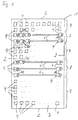
- Fig. 1 shows an embodiment of the invention designed as a spring base for a mattress Support device with a frame 1, the leg 2 comprise a lying surface 3, over which a plurality of elastic Individual support elements 4 is arranged distributed.
- a point-elastic support is realized, especially in a lateral position a particularly deep immersion of the shoulder and pelvis enables, while a normal immersion is given in reserve.
- the individual support elements 4 are arranged in rows and columns the rows parallel to the short legs 2 of the frame 1 and the Columns run perpendicular to this.
- the individual support elements 4 include an annular spring body which, for example, on a base a cross bar, which is supported and carries a flat support plate which the mattress rests on.
- the ring planes of the spring bodies 5 of the individual support elements 4 each extend perpendicular to the alignment of the rows. That way you can the spring body penetrated by a common adjusting rod 6 be in the transverse direction, i.e. parallel to the short sides 2 of the Frame 1 is stored. In fact, however, are only in the shoulder area here 7 and in the pool area 8 such adjustment rods 6 are arranged, while the remaining areas 9 have no such adjustment rods. In principle, however, they can also be provided there.
- the adjustment rods 6 carry adjustment elements 10 and are in their longitudinal direction between a first position and a second position slidably guided.
- the adjustment elements 10 In the first position of the adjusting rods 6 shown in FIG. 1 the adjustment elements 10, each of which is a single support element 4 is assigned, laterally next to the associated annular Spring body 5 and have no influence on this.
- the adjustment elements 10 In the second Position which is achieved by longitudinally displacing the adjusting rod 6, are the adjustment elements 10 within the annular spring body 5 and thereby influence its spring properties.
- the adjustment elements 10 can be designed as an elastic ring be, which rests on the inside of the annular spring body 5 and its This increases spring hardness.
- the displacement mechanism for the adjusting rods 6 can basically can be realized arbitrarily.
- the adjustment rods 6 of an area, for example the shoulder area 7 and / or the pelvic area 8 be coupled so that they are automatically adjustable together.
- a whole area 7, 8 can thus be individually customized in a simple manner Spring properties can be adapted to the needs.
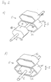
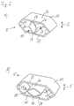
- Fig. 2 shows an embodiment of a solid adjustment body Adjustment element 10 in a single support element 4 with a Spring body 5, each of the two arranged one above the other the shape of an elongated hexagon rings 11, 12.
- the Adjustment element 10 also has the shape of an elongated hexagon on and is arranged on an adjusting rod 6, which is perpendicular extends to the ring plane of the lower ring 11 therethrough.
- the adjusting rod 6 carries further adjusting elements, not shown here 10, the number of which in particular the number of individual support elements 4 one Row of individual support elements arranged next to one another in a frame 1 4 corresponds.
- the adjustment rod 6 is in the first position shown in FIG. 2a the adjusting element 10 outside the lower ring 11. The same applies to the other adjusting elements of the adjusting rod, not shown here 6 in relation to the individual support elements 4 assigned to them.
- 2b shows the second position of the adjusting rod 6, in which the adjusting element is 10 is located within the lower ring 11. As you can see, is the adjusting element 10 on the lower longitudinal side 13 and the upper Long side 14 of the lower ring 11.
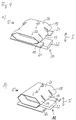
- Fig. 3 shows a variant of the adjusting elements 10, which also with individual support elements 4 can be used with a spring body, which two superimposed, the shape of an elongated hexagon having rings 11, 12 comprises.
- the adjusting element 10 is also here massive adjustment body designed and with a corresponding number further adjustment elements, not shown here, on an adjustment rod 6 arranged.
- the adjustment rod 6 is not in its longitudinal direction displaceable, but rotatably mounted about its longitudinal axis, and the adjusting elements 10 are always within the lower ring 11.
- the adjusting element In the first rotational position of the adjusting rod 6 shown in FIG. 3a is the adjusting element, which is designed as a flat, approximately cuboid body 10 with its two narrow sides 17 on the lower long side 13 and the upper longitudinal side 14 of the lower ring 11 from the inside on. With a rigid design of the adjusting element 10, the lower ring 11 blocked, so that the spring properties of the spring body 5 can only be determined by the upper ring 12. In addition, the travel is shortened accordingly. With an elastic configuration of the adjusting element 10, the adjusting element 10 determines the spring properties of the Spring body 5 in addition to the rings 11 and 12 with. The maximum Travel is only slightly shortened.
- the adjusting element 10 In the second rotational position of the adjusting rod 6 shown in FIG. 3b the adjusting element 10 is not on the lower ring 11, but the Broad sides 18 of the adjusting element 10 now lie on the long sides 13 and 14 of the ring 11 at a distance from each other.
- the lower ring 11 is therefore not blocked or the adjusting element 10 has no influence on the Spring hardness. This is therefore only determined by the two rings 11 and 12.
- the maximum travel is essentially determined by the adjustment rod 6 determines which the compression of the lower ring 11 at Applying a force in the direction of arrow I limited. Via the adjustment rod 6 can also the spring body 5 of the individual support elements 4th a whole series can be adjusted together.
- Fig. 4 shows a spring body 5 of a single support element 4 with three side by side arranged, the shape of an elongated hexagon having rings 19, the ring planes of which run parallel to one another and which are integrally connected to one another with their upper longitudinal sides 20 are.
- the two outer rings 19 are each on a support surface 21 supported, while the middle ring 19 shown in Fig. 4a Situation is unsupported.
- the middle ring 19 is also assigned a support surface 22 which is spaced from the central ring 19 and therefore only after a first spring travel to effect is coming.
- the support surface assigned to the middle ring 19 is now 22 between the first position shown in Fig. 4a and in Fig. 4b shown second position adjustable, the adjustment at least together with at least one further support surface of this type another spring body of an individual support element 4, however, this is not shown in FIG. 4.
- the support surface 22 is spaced as described to the middle ring 19.
- the support surface 22 is already without a first spring travel on the middle ring 19 so that the spring hardness of the spring body 5 determined in this position from the start by all three rings 19 becomes.
- the support surface 22 can between one single-stage and a two-stage spring characteristic of the spring body selected become.
- the ratio of the first spring travel can be varied for the second travel.
- the common adjustment of the spring body 5 of several individual support elements 4 can basically be done in any way.
- the support surfaces 22 connected to each other via an adjusting rod be between a first position in which the support surfaces 22 are spaced from the associated middle rings 19, and one second position, in which they rest against it, guided is.
- the support surfaces 22 can also simply be in one piece with one another be formed when the spring body 5 is arranged in a row accordingly are.
- FIG. 5 Another variant of an adjusting element 10 for use with a Spring body 5, which has the shape of an elongated, hexagonal Has ring 11 is shown in Fig. 5.
- the adjusting element 10 has here also the shape of an elongated, hexagonal ring 23 and is designed so that the adjusting element 10 is inserted into the ring 11 and the long sides 24 and the narrow sides 25 of the hexagonal ring 23 from the inside on the corresponding sides 26, 27 of the ring 11 abut.
- Fig. 5b This inserted position of the adjusting element 10 is shown in Fig. 5b, 5a shows the extended position of the adjusting element 10 shows.
- the spring hardness of the Spring body 5 together through the ring 11 and the adjusting element 10 determined, while in the extended position of Fig. 5a alone Ring 11 sets the spring hardness.
- the travel is practical in both cases equal.
- the common adjustment of the rings 23 of several spring bodies 5 can again be done in any way, for example via an adjusting rod connecting the adjusting elements 10.
- the variant of an adjusting element 10 shown in FIG. 6 is similar the variant shown in Fig. 5.
- the ring 23 of the adjusting element 10 is smaller than the free opening cross section of the ring 11 of the spring body 5, that is in the retracted position does not abut on all sides of the ring 11 from the inside. Rather lies only the lower long side 24 of the ring 23 on the lower long side 26 of the ring 11.
- the adjusting element is in the retracted position 10 created a two-stage spring characteristic.
- the adjusting element 10 only takes effect after a first spring travel and determines the spring hardness of the Spring body 5 with.
- In the extended position of the adjustment element 10, on the other hand is a single-stage spring characteristic.
- the adjustment of the Adjustment element 10 also takes place here in principle in any way Way together with further adjusting elements 10.
- the variant of the adjusting element 10 shown in FIG. 7 can also between a single-stage and a two-stage spring characteristic to get voted.
- the adjusting element 10 is here as a diamond-shaped ring 28 formed within the ring 11 forming the spring body 5 about an axis perpendicular to its ring surface rotatably arranged in the ring 11 is.
- the ring 28 In the first position of the adjusting element shown in FIG. 7a 10 is the ring 28 with the lying on its major axis flattened tips 29 from the inside on the two long sides 26 of the ring 11 on and therefore determines the spring hardness during the entire spring travel of the spring body 4a.
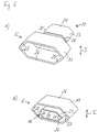
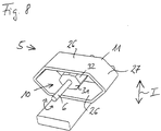
- FIG. 8 shows an adjusting element 10 in the form of an octagonal disk 31, which is centered on a ring 11, which is also hexagonal here, of a spring body 5 through adjusting rod 6 is arranged.
- adjusting rod 6 By twisting the adjusting rod 6 changes the distance between the peripheral surface 32 of the disk 31 and the two long sides 26 of the ring 11.
- the travel of the ring 11 With a rigid disk 31, the travel of the ring 11 can be in three Levels can be adjusted.
- elastic disc 31 in which case the Washer 31, the spring hardness of the spring body 5 after covering a first Co-travel determines the length of the first travel can be adjusted in three stages.
- the adjustment rod 6 carries here again several washers 31 around at least two spring bodies 5 to adjust together.
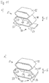
- Fig. 9 shows an adjusting element 10, which from the outside to a spring body 5 can be created.
- the spring body again in the form of an elongated, hexagonal ring 11.
- the adjusting element 10 is modeled on the lower half of the ring 11 and arranged approximately at their height.
- By moving perpendicular to The plane of the ring 11 can be the adjusting element 10 from the in Fig. 9a shown first position in the second position shown in Fig. 9b to be brought.
- the adjusting element 10 could also be directly below of the ring 11 arranged and by moving in the ring plane perpendicular to the longitudinal sides 26 of the ring 11 in the engaged position are brought from Fig. 9b.
- the adjustment element is in the first position 10 out of engagement with the ring 11 so that the spring hardness of Spring body 5 is determined solely by the ring 11.
- In the second Position of the adjusting element 10 lies on the ring 11 from below and therefore determines the spring hardness of the spring body 5. The travel is not influenced by the adjusting element 10.
- the adjusting element 10 is common here with at least one additional adjusting element in principle operated in any way.
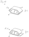
- FIG. 10 shows an adjusting element 10, which is connected to the adjusting element 10 9 corresponds.
- the adjustment between that shown in Fig. 10a Engagement position with the spring body 5 and that shown in Fig. 10b Disengaged position takes place here by turning the Adjusting element 10 about an axis extending in spring direction I.
- the adjustment is again carried out together in a fundamentally arbitrary manner with at least one additional adjustment element.
- Adjustment element 10 formed in two parts. And that exists Adjustment element 10 from two wedges 33, which between the one shown in Fig. 11a Disengaged position and the engagement position shown in Fig. 11b are pivotable. The wedges 33 are in the engaged position on the two lower narrow sides 27 of the ring 11 and determine thereby the spring properties of the spring body 5 with.
- Fig. 12 finally shows a variant in which an elastic on the Spring body 5 biased adjustment element 10 is provided.
- the spring body 5 has the shape of a elongated hexagonal ring 11, against its lower narrow sides 27 the adjusting element 10 is biased with two corresponding sides 34 is.
- these sides 34 of the adjusting element 10 against the biasing force of the narrow sides 27 of the ring 11 are moved away and kept away.
- the spring hardness of the spring body 5 determined solely by the ring 11.
- engagement position of the adjusting element 10 is the spring hardness on the other hand additionally determined by the prestressed adjusting element 10. The adjustment is again made in any way Way together with at least one other adjusting element.
- the jointly adjustable adjusting elements 10 can easily adjust the spring hardness of Single support elements 4 are made.
- the formation of the adjustment elements 10 is basically arbitrary.
- the variants shown and embodiments can also fundamentally with one another can be combined as desired.
- the adjustment elements 10 are adjusted mechanically in particular. But it can also be electro-motorized, hydraulic or pneumatic respectively. The adjustment can in all cases depend on the spring hardness and / or get the travel. In addition, the level of the spring characteristic to be changed.
- the adjustment elements 10 are either for this rigid or elastic. You can, as can the spring body 5 consist in particular of metal or plastic, or also Wood. Basically, a height adjustment of the spring body 4a possible via the adjusting elements 10 according to the invention.
- the invention can be applied in particular, as shown in FIG. 1, for slat bases for mattresses, but also in mattresses themselves or in upholstery elements as well as in the seat or the back of seating furniture.
- the jointly adjustable individual support elements 4 is only provided in certain areas of the support surface. It can provide only a part of the support surface with individual support elements 4 be, in particular the shoulder and / or pelvic area of a lying surface, while other support means such as slats are arranged are.
Landscapes
- Springs (AREA)
- Mattresses And Other Support Structures For Chairs And Beds (AREA)
- Orthopedics, Nursing, And Contraception (AREA)
- Diaphragms For Electromechanical Transducers (AREA)
- Physical Deposition Of Substances That Are Components Of Semiconductor Devices (AREA)
- Seal Device For Vehicle (AREA)
Applications Claiming Priority (2)
| Application Number | Priority Date | Filing Date | Title |
|---|---|---|---|
| DE10024530A DE10024530A1 (de) | 2000-05-18 | 2000-05-18 | Stützvorrichtung |
| DE10024530 | 2000-05-18 |
Publications (3)
| Publication Number | Publication Date |
|---|---|
| EP1155643A2 true EP1155643A2 (fr) | 2001-11-21 |
| EP1155643A3 EP1155643A3 (fr) | 2002-09-11 |
| EP1155643B1 EP1155643B1 (fr) | 2005-08-03 |
Family
ID=7642635
Family Applications (1)
| Application Number | Title | Priority Date | Filing Date |
|---|---|---|---|
| EP01111560A Expired - Lifetime EP1155643B1 (fr) | 2000-05-18 | 2001-05-11 | Dispositif de support |
Country Status (4)
| Country | Link |
|---|---|
| EP (1) | EP1155643B1 (fr) |
| AT (1) | ATE300900T1 (fr) |
| DE (3) | DE10024530A1 (fr) |
| ES (1) | ES2246958T3 (fr) |
Cited By (10)
| Publication number | Priority date | Publication date | Assignee | Title |
|---|---|---|---|---|
| EP1327404A1 (fr) * | 2002-01-07 | 2003-07-16 | Lovato s.r.l. | Elément élastique pour le support d'une partie du corps |
| EP1386564A1 (fr) * | 2002-07-31 | 2004-02-04 | Froli Kunststoffwerk Heinrich Fromme OHG | Elément élastique pour meuble d'assise ou de couchage |
| EP1716790A1 (fr) * | 2005-04-21 | 2006-11-02 | Diemer & Dr. Jaspert GbR | Système ressort |
| DE202006012078U1 (de) * | 2006-08-04 | 2007-09-27 | Froli Kunststoffwerk Heinrich Fromme Ohg | Lagerelement für eine Polsterauflage von Sitz- und Liegeflächen |
| EP3400842A1 (fr) * | 2017-05-12 | 2018-11-14 | Tournadre SA Standard Gum | Dispositif de reglage de raideur |
| CN111202383A (zh) * | 2020-01-10 | 2020-05-29 | 浙江宏都寝具有限公司 | 一种硬度可调的床垫 |
| EP3669705A1 (fr) | 2018-12-21 | 2020-06-24 | Tournadre SA Standard Gum | Element souple a raideur reglable pour meuble de couchage et/ou d'assise |
| EP3669706A1 (fr) | 2018-12-21 | 2020-06-24 | Tournadre SA Standard Gum | Element souple a hauteur reglable |
| FR3090307A1 (fr) | 2018-12-21 | 2020-06-26 | Tournadre Sa Standard Gum | Elément souple à raideur réglable pour meuble de couchage et/ou d’assise |
| US10722042B2 (en) | 2017-05-12 | 2020-07-28 | Tournadre Sa Standard Gum | Element of adjustable stiffness for beds or seats |
Families Citing this family (5)
| Publication number | Priority date | Publication date | Assignee | Title |
|---|---|---|---|---|
| DE20213821U1 (de) * | 2002-09-05 | 2003-10-16 | FROLI Kunststoffwerk Heinrich Fromme oHG, 33758 Schloß Holte-Stukenbrock | Federelement |
| FR2884883B1 (fr) * | 2005-04-22 | 2010-09-10 | Delahousse Et Fils Sa | Nouvel organe ressort pour carcasse de suspension d'un siege sommier, matelas ou autre |
| DE202006012077U1 (de) * | 2006-08-04 | 2007-09-27 | Froli Kunststoffwerk Heinrich Fromme Ohg | Lagerelement für eine Polsterauflage von Sitz- und Liegeflächen |
| DE202007004007U1 (de) * | 2007-03-14 | 2007-06-21 | Hartmann, Siegbert | Verstellbares Einzelfederelement eines Sitz- oder Liegemöbels |
| DE202007000005U1 (de) * | 2007-04-02 | 2008-05-08 | Froli Kunststoffwerk Heinrich Fromme Ohg | Lagerelement für eine Polsterauflage von Sitz- und Liegeflächen |
Family Cites Families (3)
| Publication number | Priority date | Publication date | Assignee | Title |
|---|---|---|---|---|
| US4653603A (en) * | 1983-08-25 | 1987-03-31 | Gordon Rosenmeier | Rotary fluid devices |
| CH681950A5 (fr) * | 1989-06-08 | 1993-06-30 | Superba Sa | |
| US4962916A (en) * | 1989-11-17 | 1990-10-16 | Uniroyal Chemical Company, Inc. | Compression spring |
-
2000
- 2000-05-18 DE DE10024530A patent/DE10024530A1/de not_active Withdrawn
-
2001
- 2001-05-11 ES ES01111560T patent/ES2246958T3/es not_active Expired - Lifetime
- 2001-05-11 DE DE50106940T patent/DE50106940D1/de not_active Expired - Lifetime
- 2001-05-11 EP EP01111560A patent/EP1155643B1/fr not_active Expired - Lifetime
- 2001-05-11 AT AT01111560T patent/ATE300900T1/de not_active IP Right Cessation
- 2001-05-18 DE DE20108407U patent/DE20108407U1/de not_active Expired - Lifetime
Cited By (18)
| Publication number | Priority date | Publication date | Assignee | Title |
|---|---|---|---|---|
| EP1327404A1 (fr) * | 2002-01-07 | 2003-07-16 | Lovato s.r.l. | Elément élastique pour le support d'une partie du corps |
| EP1386564A1 (fr) * | 2002-07-31 | 2004-02-04 | Froli Kunststoffwerk Heinrich Fromme OHG | Elément élastique pour meuble d'assise ou de couchage |
| JP2004065963A (ja) * | 2002-07-31 | 2004-03-04 | Froli Kunststoffwerk Heinrich Fromme Ohg | ベッド用ばね部材 |
| EP1716790A1 (fr) * | 2005-04-21 | 2006-11-02 | Diemer & Dr. Jaspert GbR | Système ressort |
| DE202006012078U1 (de) * | 2006-08-04 | 2007-09-27 | Froli Kunststoffwerk Heinrich Fromme Ohg | Lagerelement für eine Polsterauflage von Sitz- und Liegeflächen |
| US10722042B2 (en) | 2017-05-12 | 2020-07-28 | Tournadre Sa Standard Gum | Element of adjustable stiffness for beds or seats |
| EP3400842A1 (fr) * | 2017-05-12 | 2018-11-14 | Tournadre SA Standard Gum | Dispositif de reglage de raideur |
| FR3066088A1 (fr) * | 2017-05-12 | 2018-11-16 | Tournadre Sa Standard Gum | Dispositif de reglage de raideur |
| US10932586B2 (en) | 2017-05-12 | 2021-03-02 | Tournadre Sa Standard Gum | Stiffness adjustment device |
| EP3669705A1 (fr) | 2018-12-21 | 2020-06-24 | Tournadre SA Standard Gum | Element souple a raideur reglable pour meuble de couchage et/ou d'assise |
| FR3090306A1 (fr) | 2018-12-21 | 2020-06-26 | Tournadre Sa Standard Gum | Elément souple à raideur réglable pour meuble de couchage et/ou d’assise |
| FR3090307A1 (fr) | 2018-12-21 | 2020-06-26 | Tournadre Sa Standard Gum | Elément souple à raideur réglable pour meuble de couchage et/ou d’assise |
| FR3090305A1 (fr) | 2018-12-21 | 2020-06-26 | Tournadre Sa Standard Gum | Elément souple à hauteur réglable |
| EP3669706A1 (fr) | 2018-12-21 | 2020-06-24 | Tournadre SA Standard Gum | Element souple a hauteur reglable |
| US11311112B2 (en) | 2018-12-21 | 2022-04-26 | Tournadre Sa Standard Gum | Supple member with adjustable stiffness for lying and/or sitting furniture |
| US11311113B2 (en) | 2018-12-21 | 2022-04-26 | Tournadre Sa Standard Gum | Height-adjustable supple member |
| US11553803B2 (en) | 2018-12-21 | 2023-01-17 | Tournadre Sa Standard Gum | Flexible member with adjustable stiffness for lying and/or sitting furniture |
| CN111202383A (zh) * | 2020-01-10 | 2020-05-29 | 浙江宏都寝具有限公司 | 一种硬度可调的床垫 |
Also Published As
| Publication number | Publication date |
|---|---|
| DE10024530A1 (de) | 2001-11-22 |
| DE50106940D1 (de) | 2005-09-08 |
| EP1155643B1 (fr) | 2005-08-03 |
| DE20108407U1 (de) | 2001-08-02 |
| EP1155643A3 (fr) | 2002-09-11 |
| ATE300900T1 (de) | 2005-08-15 |
| ES2246958T3 (es) | 2006-03-01 |
Similar Documents
| Publication | Publication Date | Title |
|---|---|---|
| DE10116821B4 (de) | Verstellbare Armlehnenanordnung mit einem einzigen Verstellhebel | |
| EP1155643B1 (fr) | Dispositif de support | |
| EP0006840B1 (fr) | Support élastique flexible | |
| DE3728408A1 (de) | Bett | |
| DE102014207972A1 (de) | Sitzmöbelstück und Beschlag hierfür | |
| DE1963397C3 (de) | Feder für einen Federrost | |
| DE102009017896B4 (de) | Elektromotorisch verstellbare Stützeinrichtung | |
| DE2702265C2 (de) | Liegemöbelgestell mit Querlatten | |
| DE102007022023A1 (de) | Federungssystem für Matratzen | |
| DE202015101436U1 (de) | Höheneinrichtbares Seitenteil für ein Pflegebett | |
| EP1127522B1 (fr) | Bloc-ressort d'une chaise pour l'adaptation au poids | |
| DE3939024C2 (fr) | ||
| DE4442719C2 (de) | Orthopädischer Lattenrost | |
| DE202016104234U1 (de) | Höheneinrichtbares Seitenteil für ein Pflegebett | |
| DE19612079A1 (de) | Kopf- oder Fußstütze für Lattenrostliegen und Lattenrostauflage dafür | |
| EP1001696B1 (fr) | Support permettant de s'asseoir ou de s'allonger | |
| DE2616802A1 (de) | Halter fuer lotrecht regelbare fahrzeugsitze | |
| EP2322060B1 (fr) | Système de matelas pour lit | |
| EP2145568A1 (fr) | Support pour l'extrémité de latte d'un cadre a lattes | |
| DE10307738B4 (de) | Neigungsverstellvorrichtung für mindestens einen Teil einer Liege- oder Sitzfläche | |
| DE202015100471U1 (de) | Lattenrost für Liegemöbel | |
| DE2603719A1 (de) | Sprung- oder federrahmen | |
| DE20015380U1 (de) | Höhenverstellbare Auflage | |
| DE3941645C2 (fr) | ||
| DE29805898U1 (de) | Lattenrost |
Legal Events
| Date | Code | Title | Description |
|---|---|---|---|
| PUAI | Public reference made under article 153(3) epc to a published international application that has entered the european phase |
Free format text: ORIGINAL CODE: 0009012 |
|
| AK | Designated contracting states |
Kind code of ref document: A2 Designated state(s): AT BE CH CY DE DK ES FI FR GB GR IE IT LI LU MC NL PT SE TR |
|
| AX | Request for extension of the european patent |
Free format text: AL;LT;LV;MK;RO;SI |
|
| PUAL | Search report despatched |
Free format text: ORIGINAL CODE: 0009013 |
|
| AK | Designated contracting states |
Kind code of ref document: A3 Designated state(s): AT BE CH CY DE DK ES FI FR GB GR IE IT LI LU MC NL PT SE TR |
|
| AX | Request for extension of the european patent |
Free format text: AL;LT;LV;MK;RO;SI |
|
| AKX | Designation fees paid | ||
| 17P | Request for examination filed |
Effective date: 20030310 |
|
| RBV | Designated contracting states (corrected) |
Designated state(s): AT BE CH CY DE DK ES FI FR GB GR IE IT LI LU MC NL PT SE TR |
|
| REG | Reference to a national code |
Ref country code: DE Ref legal event code: 8566 |
|
| GRAP | Despatch of communication of intention to grant a patent |
Free format text: ORIGINAL CODE: EPIDOSNIGR1 |
|
| GRAS | Grant fee paid |
Free format text: ORIGINAL CODE: EPIDOSNIGR3 |
|
| RAP1 | Party data changed (applicant data changed or rights of an application transferred) |
Owner name: JASPERT, BODO F., DR. Owner name: DIEMER, GREGOR |
|
| RIN1 | Information on inventor provided before grant (corrected) |
Inventor name: DIEMER, GREGOR Inventor name: JASPERT, BODO F., DR. |
|
| RAP1 | Party data changed (applicant data changed or rights of an application transferred) |
Owner name: DIEMER & DR. JASPERT GBR |
|
| RIN1 | Information on inventor provided before grant (corrected) |
Inventor name: DIEMER & DR. JASPERT GBR |
|
| GRAA | (expected) grant |
Free format text: ORIGINAL CODE: 0009210 |
|
| AK | Designated contracting states |
Kind code of ref document: B1 Designated state(s): AT BE CH CY DE DK ES FI FR GB GR IE IT LI LU MC NL PT SE TR |
|
| PG25 | Lapsed in a contracting state [announced via postgrant information from national office to epo] |
Ref country code: FI Free format text: LAPSE BECAUSE OF FAILURE TO SUBMIT A TRANSLATION OF THE DESCRIPTION OR TO PAY THE FEE WITHIN THE PRESCRIBED TIME-LIMIT Effective date: 20050803 Ref country code: TR Free format text: LAPSE BECAUSE OF FAILURE TO SUBMIT A TRANSLATION OF THE DESCRIPTION OR TO PAY THE FEE WITHIN THE PRESCRIBED TIME-LIMIT Effective date: 20050803 Ref country code: IE Free format text: LAPSE BECAUSE OF FAILURE TO SUBMIT A TRANSLATION OF THE DESCRIPTION OR TO PAY THE FEE WITHIN THE PRESCRIBED TIME-LIMIT Effective date: 20050803 |
|
| REG | Reference to a national code |
Ref country code: GB Ref legal event code: FG4D Free format text: NOT ENGLISH |
|
| REG | Reference to a national code |
Ref country code: CH Ref legal event code: EP |
|
| REG | Reference to a national code |
Ref country code: IE Ref legal event code: FG4D Free format text: LANGUAGE OF EP DOCUMENT: GERMAN |
|
| REF | Corresponds to: |
Ref document number: 50106940 Country of ref document: DE Date of ref document: 20050908 Kind code of ref document: P |
|
| GBT | Gb: translation of ep patent filed (gb section 77(6)(a)/1977) |
Effective date: 20051010 |
|
| PG25 | Lapsed in a contracting state [announced via postgrant information from national office to epo] |
Ref country code: GR Free format text: LAPSE BECAUSE OF FAILURE TO SUBMIT A TRANSLATION OF THE DESCRIPTION OR TO PAY THE FEE WITHIN THE PRESCRIBED TIME-LIMIT Effective date: 20051103 Ref country code: DK Free format text: LAPSE BECAUSE OF FAILURE TO SUBMIT A TRANSLATION OF THE DESCRIPTION OR TO PAY THE FEE WITHIN THE PRESCRIBED TIME-LIMIT Effective date: 20051103 |
|
| REG | Reference to a national code |
Ref country code: SE Ref legal event code: TRGR |
|
| PG25 | Lapsed in a contracting state [announced via postgrant information from national office to epo] |
Ref country code: PT Free format text: LAPSE BECAUSE OF FAILURE TO SUBMIT A TRANSLATION OF THE DESCRIPTION OR TO PAY THE FEE WITHIN THE PRESCRIBED TIME-LIMIT Effective date: 20060103 |
|
| REG | Reference to a national code |
Ref country code: ES Ref legal event code: FG2A Ref document number: 2246958 Country of ref document: ES Kind code of ref document: T3 |
|
| REG | Reference to a national code |
Ref country code: IE Ref legal event code: FD4D |
|
| ET | Fr: translation filed | ||
| PG25 | Lapsed in a contracting state [announced via postgrant information from national office to epo] |
Ref country code: MC Free format text: LAPSE BECAUSE OF NON-PAYMENT OF DUE FEES Effective date: 20060531 |
|
| PLBE | No opposition filed within time limit |
Free format text: ORIGINAL CODE: 0009261 |
|
| STAA | Information on the status of an ep patent application or granted ep patent |
Free format text: STATUS: NO OPPOSITION FILED WITHIN TIME LIMIT |
|
| 26N | No opposition filed |
Effective date: 20060504 |
|
| PG25 | Lapsed in a contracting state [announced via postgrant information from national office to epo] |
Ref country code: LU Free format text: LAPSE BECAUSE OF NON-PAYMENT OF DUE FEES Effective date: 20060511 |
|
| PG25 | Lapsed in a contracting state [announced via postgrant information from national office to epo] |
Ref country code: CY Free format text: LAPSE BECAUSE OF FAILURE TO SUBMIT A TRANSLATION OF THE DESCRIPTION OR TO PAY THE FEE WITHIN THE PRESCRIBED TIME-LIMIT Effective date: 20050803 |
|
| PGFP | Annual fee paid to national office [announced via postgrant information from national office to epo] |
Ref country code: ES Payment date: 20090521 Year of fee payment: 9 |
|
| PGFP | Annual fee paid to national office [announced via postgrant information from national office to epo] |
Ref country code: SE Payment date: 20090514 Year of fee payment: 9 |
|
| PGFP | Annual fee paid to national office [announced via postgrant information from national office to epo] |
Ref country code: GB Payment date: 20090522 Year of fee payment: 9 |
|
| PGFP | Annual fee paid to national office [announced via postgrant information from national office to epo] |
Ref country code: CH Payment date: 20100726 Year of fee payment: 10 |
|
| PGFP | Annual fee paid to national office [announced via postgrant information from national office to epo] |
Ref country code: AT Payment date: 20100723 Year of fee payment: 10 Ref country code: IT Payment date: 20100727 Year of fee payment: 10 |
|
| GBPC | Gb: european patent ceased through non-payment of renewal fee |
Effective date: 20100511 |
|
| EUG | Se: european patent has lapsed | ||
| PGFP | Annual fee paid to national office [announced via postgrant information from national office to epo] |
Ref country code: BE Payment date: 20100729 Year of fee payment: 10 |
|
| PG25 | Lapsed in a contracting state [announced via postgrant information from national office to epo] |
Ref country code: SE Free format text: LAPSE BECAUSE OF NON-PAYMENT OF DUE FEES Effective date: 20100512 |
|
| REG | Reference to a national code |
Ref country code: ES Ref legal event code: FD2A Effective date: 20110714 |
|
| PG25 | Lapsed in a contracting state [announced via postgrant information from national office to epo] |
Ref country code: ES Free format text: LAPSE BECAUSE OF NON-PAYMENT OF DUE FEES Effective date: 20110704 Ref country code: GB Free format text: LAPSE BECAUSE OF NON-PAYMENT OF DUE FEES Effective date: 20100511 |
|
| PGFP | Annual fee paid to national office [announced via postgrant information from national office to epo] |
Ref country code: FR Payment date: 20110607 Year of fee payment: 11 |
|
| PGFP | Annual fee paid to national office [announced via postgrant information from national office to epo] |
Ref country code: NL Payment date: 20110520 Year of fee payment: 11 |
|
| PG25 | Lapsed in a contracting state [announced via postgrant information from national office to epo] |
Ref country code: ES Free format text: LAPSE BECAUSE OF NON-PAYMENT OF DUE FEES Effective date: 20100512 |
|
| BERE | Be: lapsed |
Owner name: *DIEMER & JASPERT GBR Effective date: 20110531 |
|
| REG | Reference to a national code |
Ref country code: CH Ref legal event code: PL |
|
| PG25 | Lapsed in a contracting state [announced via postgrant information from national office to epo] |
Ref country code: CH Free format text: LAPSE BECAUSE OF NON-PAYMENT OF DUE FEES Effective date: 20110531 Ref country code: LI Free format text: LAPSE BECAUSE OF NON-PAYMENT OF DUE FEES Effective date: 20110531 |
|
| REG | Reference to a national code |
Ref country code: AT Ref legal event code: MM01 Ref document number: 300900 Country of ref document: AT Kind code of ref document: T Effective date: 20110511 |
|
| PG25 | Lapsed in a contracting state [announced via postgrant information from national office to epo] |
Ref country code: IT Free format text: LAPSE BECAUSE OF NON-PAYMENT OF DUE FEES Effective date: 20110511 Ref country code: AT Free format text: LAPSE BECAUSE OF NON-PAYMENT OF DUE FEES Effective date: 20110511 |
|
| PG25 | Lapsed in a contracting state [announced via postgrant information from national office to epo] |
Ref country code: BE Free format text: LAPSE BECAUSE OF NON-PAYMENT OF DUE FEES Effective date: 20110531 |
|
| REG | Reference to a national code |
Ref country code: NL Ref legal event code: V1 Effective date: 20121201 |
|
| PGFP | Annual fee paid to national office [announced via postgrant information from national office to epo] |
Ref country code: DE Payment date: 20120730 Year of fee payment: 12 |
|
| REG | Reference to a national code |
Ref country code: FR Ref legal event code: ST Effective date: 20130131 |
|
| PG25 | Lapsed in a contracting state [announced via postgrant information from national office to epo] |
Ref country code: NL Free format text: LAPSE BECAUSE OF NON-PAYMENT OF DUE FEES Effective date: 20121201 |
|
| PG25 | Lapsed in a contracting state [announced via postgrant information from national office to epo] |
Ref country code: FR Free format text: LAPSE BECAUSE OF NON-PAYMENT OF DUE FEES Effective date: 20120531 |
|
| PG25 | Lapsed in a contracting state [announced via postgrant information from national office to epo] |
Ref country code: DE Free format text: LAPSE BECAUSE OF NON-PAYMENT OF DUE FEES Effective date: 20131203 |
|
| REG | Reference to a national code |
Ref country code: DE Ref legal event code: R119 Ref document number: 50106940 Country of ref document: DE Effective date: 20131203 |