EP3669705A1 - Element souple a raideur reglable pour meuble de couchage et/ou d'assise - Google Patents
Element souple a raideur reglable pour meuble de couchage et/ou d'assise Download PDFInfo
- Publication number
- EP3669705A1 EP3669705A1 EP19219018.9A EP19219018A EP3669705A1 EP 3669705 A1 EP3669705 A1 EP 3669705A1 EP 19219018 A EP19219018 A EP 19219018A EP 3669705 A1 EP3669705 A1 EP 3669705A1
- Authority
- EP
- European Patent Office
- Prior art keywords
- adjustable
- springs
- central axis
- flexible element
- stiffness
- Prior art date
- Legal status (The legal status is an assumption and is not a legal conclusion. Google has not performed a legal analysis and makes no representation as to the accuracy of the status listed.)
- Granted
Links
Images


Classifications
-
- A—HUMAN NECESSITIES
- A47—FURNITURE; DOMESTIC ARTICLES OR APPLIANCES; COFFEE MILLS; SPICE MILLS; SUCTION CLEANERS IN GENERAL
- A47C—CHAIRS; SOFAS; BEDS
- A47C23/00—Spring mattresses with rigid frame or forming part of the bedstead, e.g. box springs; Divan bases; Slatted bed bases
- A47C23/002—Spring mattresses with rigid frame or forming part of the bedstead, e.g. box springs; Divan bases; Slatted bed bases with separate resilient support elements, e.g. elastomeric springs arranged in a two-dimensional matrix pattern
-
- A—HUMAN NECESSITIES
- A47—FURNITURE; DOMESTIC ARTICLES OR APPLIANCES; COFFEE MILLS; SPICE MILLS; SUCTION CLEANERS IN GENERAL
- A47C—CHAIRS; SOFAS; BEDS
- A47C23/00—Spring mattresses with rigid frame or forming part of the bedstead, e.g. box springs; Divan bases; Slatted bed bases
- A47C23/04—Spring mattresses with rigid frame or forming part of the bedstead, e.g. box springs; Divan bases; Slatted bed bases using springs in compression, e.g. coiled
- A47C23/043—Spring mattresses with rigid frame or forming part of the bedstead, e.g. box springs; Divan bases; Slatted bed bases using springs in compression, e.g. coiled using wound springs
- A47C23/0435—Spring mattresses with rigid frame or forming part of the bedstead, e.g. box springs; Divan bases; Slatted bed bases using springs in compression, e.g. coiled using wound springs of adjustable resilience
-
- A—HUMAN NECESSITIES
- A47—FURNITURE; DOMESTIC ARTICLES OR APPLIANCES; COFFEE MILLS; SPICE MILLS; SUCTION CLEANERS IN GENERAL
- A47C—CHAIRS; SOFAS; BEDS
- A47C23/00—Spring mattresses with rigid frame or forming part of the bedstead, e.g. box springs; Divan bases; Slatted bed bases
- A47C23/04—Spring mattresses with rigid frame or forming part of the bedstead, e.g. box springs; Divan bases; Slatted bed bases using springs in compression, e.g. coiled
- A47C23/05—Frames therefor; Connecting the springs to the frame ; Interconnection of springs, e.g. in spring units
-
- A—HUMAN NECESSITIES
- A47—FURNITURE; DOMESTIC ARTICLES OR APPLIANCES; COFFEE MILLS; SPICE MILLS; SUCTION CLEANERS IN GENERAL
- A47C—CHAIRS; SOFAS; BEDS
- A47C27/00—Spring, stuffed or fluid mattresses or cushions specially adapted for chairs, beds or sofas
- A47C27/04—Spring, stuffed or fluid mattresses or cushions specially adapted for chairs, beds or sofas with spring inlays
- A47C27/06—Spring inlays or spring units therefor
- A47C27/061—Spring inlays or spring units therefor of adjustable resiliency
-
- A—HUMAN NECESSITIES
- A47—FURNITURE; DOMESTIC ARTICLES OR APPLIANCES; COFFEE MILLS; SPICE MILLS; SUCTION CLEANERS IN GENERAL
- A47C—CHAIRS; SOFAS; BEDS
- A47C7/00—Parts, details, or accessories of chairs or stools
- A47C7/02—Seat parts
- A47C7/34—Seat parts with springs in compression, e.g. coiled
- A47C7/342—Edge stiffeners
-
- A—HUMAN NECESSITIES
- A47—FURNITURE; DOMESTIC ARTICLES OR APPLIANCES; COFFEE MILLS; SPICE MILLS; SUCTION CLEANERS IN GENERAL
- A47C—CHAIRS; SOFAS; BEDS
- A47C7/00—Parts, details, or accessories of chairs or stools
- A47C7/02—Seat parts
- A47C7/34—Seat parts with springs in compression, e.g. coiled
- A47C7/345—Seat parts with springs in compression, e.g. coiled of adjustable resilience
Definitions
- the present disclosure relates to the field of furniture and more particularly a flexible element with adjustable stiffness for sleeping and / or seating furniture.
- “sleeping and / or seating furniture” is meant not only furniture intended for domestic use or in collective installations, but also, for example, seats, beds, berths, and / or stretchers means of transport.
- the present disclosure aims to remedy the aforementioned drawbacks, by proposing a flexible element with adjustable stiffness for seating and / or sleeping furniture, with a simple structure and a limited space requirement.
- the flexible element may include one or more adjustable springs, each configured to deform radially relative to a central axis under the effect of an axial stress along the central axis, and a rotary part comprising a hub capable of rotating around the central axis and one or more elastically flexible fingers, each extending from a first end integral with the hub of the rotary part, on an arc of a circle around the axis central, up to a second end, which may in particular be a free end, and each cooperating, in a radial direction relative to the central axis, with one or more of the adjustable springs.
- Each adjustable spring can in particular be a helical spring, although other forms are also possible.
- the rotation of the rotary part around the central axis makes it possible to vary a cantilever, in a plane perpendicular to the central axis, of a fulcrum of each spring adjustable on the finger elastically flexible, relative to the first end of the elastically flexible finger. Thanks to the variation of this overhang, it is possible to adjust, even gradually, the resistance that the finger will oppose to a radial stress exerted by the adjustable spring relative to the central axis, and therefore to compression of the adjustable spring along the central axis.
- the adjustable springs can comprise one or more pairs of adjustable springs, each pair of adjustable springs comprising an upper adjustable spring and a lower adjustable spring, the ends of which are connected by a corresponding articulation with a pivot axis orthogonal to the central axis.
- each finger can cross a space defined by a pair of jaws associated with the corresponding joint.
- the adjustable upper and lower springs can thus be arranged in series and jointly adjustable.
- other arrangements are also possible, such as for example that each finger forms the pivot of the corresponding joint connecting an upper adjustable spring and a lower adjustable spring.
- the flexible element may further comprise one or more internal coaxial springs of the adjustable springs.
- the internal springs can be helical, comprising at least two springs arranged in series and / or at least two springs arranged in parallel. However, other arrangements and / or alternative forms are also possible.
- a second aspect of the present disclosure relates to an assembly comprising a plurality of flexible elements with adjustable stiffness such as the aforementioned flexible element, in parallel orientation.
- Such a set can therefore provide a bearing surface whose firmness will be adjustable by the stiffness of the flexible elements. It is conceivable that the rotating parts of the flexible elements of this assembly are coupled in rotation, so as to allow the simultaneous adjustment of the stiffness of several flexible elements of the assembly.
- a third aspect of the present disclosure relates to a sleeping or seating unit comprising one or more assemblies such as the aforementioned assembly. These assemblies can be integrated, for example, into a mattress, box spring and / or cushion forming part of the piece of furniture.
- a fourth aspect of the present disclosure relates to a method of using a flexible element with adjustable stiffness such as the aforementioned element, comprising at least one step of rotation of the rotary part to adjust the stiffness of the flexible element to adjustable stiffness.
- This flexible element 10 can comprise several springs oriented along this central axis Z.
- the flexible element 10 can comprise, one or more internal springs 11.
- these internal springs 11 can in particular be helical springs arranged in pairs, each pair of internal springs 11 comprising two springs arranged in parallel, and the pairs being arranged in series between an upper support 12 and a lower support 13 at the ends of the flexible element 10 along the central axis Z, and connected by a central body 14.
- the internal springs could possibly be in different numbers, be differently arranged, or even take an entirely different shape, such as foam springs.
- the flexible element 10 may further comprise one or more adjustable springs.
- These adjustable springs can in particular be helical springs arranged coaxial with the internal springs 11 radially outside of these with respect to the central axis X, although other configurations are possible.
- the flexible element 10 comprises two pairs of adjustable helical springs, a different number of adjustable helical springs, equal to or greater than one, is also conceivable.
- the adjustable springs can in particular be arranged in pairs, and each pair may comprise an upper adjustable spring 15 and a lower adjustable spring 16, connected together, at ends 15a, 16a, by a corresponding articulation 17 with a pivot axis X orthogonal to the axis central Z and offset radially from it.
- Opposite ends 15b and 16b of the adjustable upper 15 and lower 16 springs may be integral with an upper support 12 and a lower support 13 of the flexible element 10, respectively.
- the flexible element 10 may comprise a rotary part 20 able to rotate around the central axis Z.
- this rotary part 20 can comprise a hub 21 engaged around the central body 14 so as to be able to rotate around the central axis Z relative to this central body 14, while restricting their relative movement in the direction of the central axis Z.
- the rotary part 20 may comprise one or more radial arms 22 extending from the hub 21 and integral with the latter, and one or more elastically flexible fingers 23, each extending on an arc of circle around the central axis Z, from a first end 23a secured to the hub 21 through one of the radial arms 22, to a second end 23b, which can be, as illustrated, a free end.
- the rotary part 20 may comprise connections 24 for its actuation in rotation.
- each articulation 17 can comprise one or more pairs of jaws 18, each pair of jaws 18 defining a space 19 receiving one of the fingers 23. As illustrated, this space 19 defined by the jaws 18 can be closed all around the finger 23 .
- the rotation of the rotary part 20 around the central axis Z makes it possible to increase and / or decrease the overhang b of each corresponding articulation 17, in a plane perpendicular to the central axis Z, by relative to the first end 23a of the corresponding finger 23, so as to gradually adjust the resistance that the finger 23 will oppose in bending to the radial displacement of the joint 17 relative to the central axis Z, and therefore to the compression flexible element 10.
- Each of the components of the flexible element 10 can be made of organic polymer material, and produced in particular by injection molding. As illustrated on figs. 5 to 7 , several similar flexible elements 10 can be combined into a single assembly 100 within a sleeping and / or seating unit, such as for example the bed 200 of the figure 6 or the 300 sofa figure 7 .
- this assembly 100 the central axes Z of the flexible elements 10 can be oriented in parallel, and the rotary parts 20 can be coupled in rotation, so as to allow the simultaneous adjustment of the stiffness of several flexible elements 10 of the assembly 100.
- the set 100 can be integrated into a mattress, box spring or cushion. It is also conceivable to integrate several assemblies 100, with adjustable stiffness separately, in a single mattress, box spring or cushion, so as to allow the user to adjust the stiffness by separate zones for better comfort.
Landscapes
- Mattresses And Other Support Structures For Chairs And Beds (AREA)
- Chair Legs, Seat Parts, And Backrests (AREA)
Abstract
Description
- La présente divulgation concerne le domaine de l'ameublement et plus particulièrement un élément souple à raideur réglable pour meuble de couchage et/ou d'assise. Par « meuble de couchage et/ou d'assisse » l'on entend non seulement des meubles destinés à l'usage domestique ou dans des installations collectives, mais aussi, par exemple, les sièges, lits, couchettes, et/ou civières destinés aux moyens de transport.
- Afin de rendre une surface d'assise, de dossier ou de couchage adaptable aux préférences et à l'anatomie de différents utilisateurs, des ensembles, tels que des matelas ou des sommiers, avec des éléments souples à raideur réglable ont été précédemment divulgués, par exemple dans
EP 1 386 564 A1 ,EP 1 155 643 A2 ,WO 2008/015235 ,WO 96/27312 US 4,667,357 ouDE 10 2008 050 108 A1 . Typiquement, la raideur des éléments y est réglée avec des restrictions à leur déformation mécanique. Pour cela, toutefois, les mécanismes proposés présentent une importante complexité et/ou encombrement. - La présente divulgation vise à remédier aux inconvénients susmentionnés, en proposant un élément souple à raideur réglable pour meuble d'assise et/ou de couchage, avec une structure simple et un encombrement limité.
- Pour atteindre ce but, suivant un premier aspect de cette divulgation, l'élément souple peut comprendre un ou plusieurs ressorts réglables, configurés chacun pour se déformer radialement par rapport à un axe central sous effet d'une contrainte axiale suivant l'axe central, et une pièce rotative comportant un moyeu apte à tourner autour de l'axe central et un ou plusieurs doigts élastiquement flexibles, s'étendant chacun à partir d'une première extrémité solidaire du moyeu de la pièce rotative, sur un arc de cercle autour de l'axe central, jusqu'à une seconde extrémité, qui peut notamment être une extrémité libre, et coopérant chacun, en direction radiale par rapport à l'axe central, avec un ou plusieurs des ressorts réglables. Chaque ressort réglable peut notamment être un ressort hélicoïdal, quoique d'autres formes soient également envisageables.
- Ainsi, la rotation de la pièce rotative autour de l'axe central permet de faire varier un porte-à-faux, dans un plan perpendiculaire à l'axe central, d'un point d'appui de chaque ressort réglable sur le doigt élastiquement flexible, par rapport à la première extrémité du doigt élastiquement flexible. Grâce à la variation de ce porte-à-faux, il est possible de régler, même de manière graduelle, la résistance que le doigt va opposer à une contrainte radiale exercée par le ressort réglable par rapport à l'axe central, et donc à la compression du ressort réglable suivant l'axe central.
- Les ressorts réglables peuvent comprendre une ou plusieurs paires de ressorts réglables, chaque paire de ressorts réglables comprenant un ressort réglable supérieur et un ressort réglable inférieur dont des extrémités sont reliées par une articulation correspondante avec un axe de pivotement orthogonal à l'axe central. En particulier, chaque doigt peut traverser un espace défini par une paire de mâchoires associée à l'articulation correspondante. Les ressorts réglables supérieur et inférieur peuvent ainsi être agencés en série et conjointement réglables. Toutefois, d'autres arrangements sont également envisageables, comme par exemple que chaque doigt forme le pivot de l'articulation correspondante reliant un ressort réglable supérieur et un ressort réglable inférieur.
- L'élément souple peut comporter en outre un ou plusieurs ressorts internes coaxiaux des ressorts réglables. Les ressorts internes peuvent être hélicoïdaux, comprendre au moins deux ressorts disposés en série et/ou au moins deux ressorts disposés en parallèle. Toutefois, d'autres arrangements et/ou formes alternatives sont également envisageables.
- Un deuxième aspect de la présente divulgation concerne un ensemble comprenant une pluralité d'éléments souples à raideur réglable tels que l'élément souple susmentionné, parallèlement orientés. Un tel ensemble peut donc fournir une surface d'appui dont la fermeté sera réglable par la raideur des éléments souples. Il est envisageable que les pièces rotatives des éléments souples de cet ensemble soient couplées en rotation, de manière à permettre le réglage simultané de la raideur de plusieurs éléments souples de l'ensemble.
- Un troisième aspect de la présente divulgation concerne un meuble de couchage ou d'assise comprenant un ou plusieurs ensembles tels que l'ensemble susmentionné. Ces ensembles peuvent être intégrés, par exemple, dans un matelas, sommier et/ou coussin formant partie du meuble.
- Un quatrième aspect de la présente divulgation concerne un procédé d'utilisation d'un élément souple à raideur réglable tel que l'élément susmentionné, comprenant au moins une étape de rotation de la pièce rotative pour régler la raideur de l'élément de souple à raideur réglable.
- L'invention sera bien comprise et ses avantages apparaîtront mieux, à la lecture de la description détaillée qui suit, d'un mode de réalisation représenté à titre d'exemple non limitatif. La description se réfère aux dessins annexés sur lesquels :
-
- [
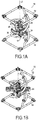
Fig. 1A ] Lafigure 1A est une vue en perspective d'un élément souple suivant en mode de réalisation, avec une pièce rotative en une première position. - [
Fig. 1B ] Lafigure 1B est une vue en perspective d'un élément souple suivant en mode de réalisation, avec une pièce rotative en une deuxième position. - [
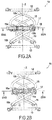
Fig. 2A ] Lafigure 2A est une vue latérale de l'élément souple desfigures 1A et 1B , avec la pièce rotative dans la première position. - [
Fig. 2B ] Lafigure 2B est une vue latérale de l'élément souple desfigures 1A et 1B , avec la pièce rotative dans la deuxième position. - [
Fig. 3A ] Lafigure 3A est une vue en coupe, dans un plan perpendiculaire à un axe central, de l'élément souple desfigures 1A et 1B , avec la pièce rotative dans la première position. - [
Fig. 3B ] Lafigure 3B est une vue en coupe, dans un plan perpendiculaire à un axe central, de l'élément souple desfigures 1A et 1B , avec la pièce rotative dans la deuxième position. - [
Fig. 4 ] Lafigure 4 est une vue de détail d'une articulation de l'élément souple des figures précédentes. - [
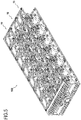
Fig. 5 ] Lafigure 5 est une vue en perspective d'un ensemble de plusieurs éléments souples analogues à celui des figures précédentes. - [
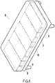
Fig. 6 ] Lafigure 6 est une vue schématique d'un lit incorporant des ensembles analogues à celui de lafigure 5 . - [
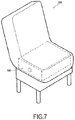
Fig. 7 ] Lafigure 7 est une vue schématique d'un sofa incorporant un ensemble analogue à celui de lafigure 5 . - Un élément souple 10, destiné aux meubles d'assise ou de couchage, tels que, par exemple, les lits, canapés, canapés-lits, sofas, etc., et dont la raideur en compression suivant un axe central Z est réglable, est illustré sur les
figures 1A à 3B . Cet élément souple 10 peut comprendre plusieurs ressorts orientés suivant cet axe central Z. Ainsi, l'élément souple 10 peut comprendre, un ou plusieurs ressorts internes 11. Comme illustré, ces ressorts internes 11 peuvent notamment être des ressorts hélicoïdaux arrangés par paires, chaque paire de ressorts internes 11 comprenant deux ressorts agencés en parallèle, et les paires étant agencées en série entre un support supérieur 12 et un support inférieur 13 aux extrémités de l'élément souple 10 suivant l'axe central Z, et reliées par un corps central 14. Toutefois, les ressorts internes pourraient éventuellement être en nombre différent, être différemment arrangés, voire prendre une forme entièrement différente, comme par exemple des ressorts en mousse. - L'élément souple 10 peut comprendre en outre un ou plusieurs ressorts réglables. Ces ressorts réglables peuvent notamment être des ressorts hélicoïdaux disposés coaxiaux aux ressorts internes 11 radialement à l'extérieur de ceux-ci par rapport à l'axe central X, quoique d'autres configurations soient envisageables. Bien que, dans l'exemple illustré sur les
figures 1A à 3B , l'élément souple 10 comporte deux paires de ressorts hélicoïdaux réglables, un nombre différent de ressorts hélicoïdaux réglables, égal ou supérieur à un, est également envisageable. Comme illustré, les ressorts réglables peuvent notamment être arrangés par paires, et chaque paire peut comprendre un ressort réglable supérieur 15 et un ressort réglable inférieur 16, reliés entre eux, à des extrémités 15a,16a, par une articulation 17 correspondante avec un axe de pivotement X orthogonal à l'axe central Z et décalé radialement par rapport à celui-ci. Des extrémités opposées 15b et 16b des ressorts réglables supérieur 15 et inférieur 16 peuvent être solidaires d'un support supérieur 12 et d'un support inférieur 13 de l'élément souple 10, respectivement. - En outre, l'élément souple 10 peut comprendre une pièce rotative 20 apte à tourner autour de l'axe central Z. Comme illustré sur les
figures 1A à 3B , cette pièce rotative 20 peut comprendre un moyeu 21 engagé autour du corps central 14 de manière à pouvoir tourner autour de l'axe central Z par rapport à ce corps central 14, tout en restreignant leur mouvement relatif dans la direction de l'axe central Z. En outre, la pièce rotative 20 peut comprendre un ou plusieurs bras radiaux 22 s'étendant à partir du moyeu 21 et solidaires de celui-ci, et un ou plusieurs doigts 23 élastiquement flexibles, s'étendant chacun, sur un arc de cercle autour de l'axe central Z, d'une première extrémité 23a solidaire du moyeu 21 à travers l'un des bras radiaux 22, jusqu'à une deuxième extrémité 23b, qui peut être, comme illustré, une extrémité libre. Par ailleurs, la pièce rotative 20 peut comprendre des connexions 24 pour son actionnement en rotation. - Comme illustré en détail sur la
figure 4 , chaque articulation 17 peut comprendre une ou plusieurs paires de mâchoires 18, chaque paire de mâchoires 18 définissant un espace 19 recevant l'un des doigts 23. Comme illustré, cet espace 19 défini par les mâchoires 18 peut être fermé tout autour du doigt 23. - En fonctionnement, la rotation de la pièce rotative 20 autour de l'axe central Z permet d'augmenter et/ou diminuer le porte-à-faux b de chaque articulation 17 correspondante, dans un plan perpendiculaire à l'axe central Z, par rapport à la première extrémité 23a du doigt 23 correspondant, pour régler ainsi graduellement la résistance que le doigt 23 va opposer en flexion au déplacement radial de l'articulation 17 par rapport à l'axe central Z, et donc à la compression de l'élément souple 10. Ainsi, quand le porte-à-faux b est plus réduit, comme dans la position angulaire de la pièce rotative 20 illustrée sur les
Figs 1A ,2A et3A , la résistance opposée par les doigts 23 au déplacement radial des articulations 17 correspondantes, et donc à la compression de l'élément souple 10 suivant l'axe central, va être plus élevée que quand le porte-à-faux b est plus prononcé, comme illustré sur la figureFigs. 1B ,2B et3B . - Chacun des composants de l'élément souple 10 peut être en matière polymère organique, et produit notamment par moulage-injection. Comme illustré sur les
figs. 5 à 7 , plusieurs éléments souples 10 analogues peuvent être combinés en un seul ensemble 100 au sein d'un meuble de couchage et/ou d'assise, comme par exemple le lit 200 de lafigure 6 ou le sofa 300 de lafigure 7 . Dans cet ensemble 100, les axes centraux Z des éléments souples 10 peuvent être parallèlement orientés, et les pièces rotatives 20 peuvent être couplées en rotation, de manière à permettre le réglage simultané de la raideur de plusieurs éléments souples 10 de l'ensemble 100. L'ensemble 100 peut être intégré dans un matelas, sommier ou coussin. Il est également envisageable d'intégrer plusieurs ensembles 100, à raideur réglable séparément, dans un seul matelas, sommier ou coussin, de manière à permettre à l'utilisateur de régler la raideur par zones séparées pour un meilleur confort. - Quoique la présente invention ait été décrite en se référant à des exemples spécifiques, il est évident que des différentes modifications et changements peuvent être effectués sur ces exemples sans sortir de la portée générale de l'invention telle que définie par les revendications. Par conséquent, la description et les dessins doivent être considérés dans un sens illustratif plutôt que restrictif.
Claims (12)
- Elément souple (10) à raideur réglable pour meuble de couchage et/ou d'assise (200,300), comprenant :un ou plusieurs ressorts réglables (15, 16), configurés chacun pour se déformer radialement par rapport à un axe central (Z) sous effet d'une contrainte axiale suivant l'axe central (Z),etune pièce rotative (20) comportant un moyeu (21) apte à tourner autour de l'axe central et un ou plusieurs doigts (23), élastiquement flexibles dans un plan perpendiculaire à l'axe central (Z), s'étendant chacun à partir d'une première extrémité (23a) solidaire du moyeu (21) de la pièce rotative (20), sur un arc de cercle (A) autour de l'axe central (Z), jusqu'à une seconde extrémité (23b), et coopérant chacun, en direction radiale par rapport à l'axe central (Z), avec un ou plusieurs des ressorts réglables (15,16).
- Elément souple à raideur variable suivant la revendication 1, dans lequel la seconde extrémité (23a) de chaque doigt (23) est une extrémité libre.
- Elément souple (10) à raideur réglable suivant l'une quelconque des revendications 1 ou 2, dans lequel chaque ressort réglable (15,16) est un ressort hélicoïdal disposé autour de l'axe central (Z).
- Elément souple (10) à raideur réglable suivant l'une quelconque des revendications 1 à 3, dans lequel les ressorts réglables (15,16) comprennent une ou plusieurs paires de ressorts réglables (15,16), chaque paire de ressorts réglables (15,16) comprenant un ressort réglable supérieur (15) et un ressort réglable inférieur (16) dont des extrémités (15a,16a) sont reliées par une articulation (17) correspondante avec un axe de pivotement (X) orthogonal à l'axe central (Z).
- Elément souple (10) à raideur réglable suivant la revendication 4, dans lequel chaque doigt (23) traverse un espace (19) défini par une paire de mâchoires (18) associée à l'articulation (17) correspondante.
- Elément souple (10) à raideur réglable suivant l'une quelconque des revendications 1 à 5, comportant en outre un ou plusieurs ressorts internes (11) coaxiaux des ressorts réglables (15,16).
- Elément souple (10) à raideur réglable suivant la revendication 6, dans lequel les ressorts internes (11) comprennent au moins deux ressorts disposés en série.
- Elément souple (10) à raideur réglable suivant l'une quelconque des revendications 6 ou 7, dans lequel les ressorts internes (11) comprennent au moins deux ressorts disposés en parallèle.
- Elément souple (10) à raideur réglable suivant l'une quelconque des revendications 6 à 8, dans lequel les ressorts internes (11) sont hélicoïdaux.
- Ensemble (100) comprenant une pluralité d'éléments souples (10) à raideur réglable suivant l'une quelconque des revendications précédentes, parallèlement orientés.
- Meuble de couchage ou d'assise (200,300) comprenant un ou plusieurs ensembles suivant la revendication 10.
- Procédé d'utilisation d'un élément souple (10) à raideur réglable suivant l'une quelconque des revendications 1 à 9, comprenant au moins une étape de rotation de la pièce rotative (20) pour régler la raideur de l'élément souple (10) à raideur réglable.
Priority Applications (1)
| Application Number | Priority Date | Filing Date | Title |
|---|---|---|---|
| PL19219018T PL3669705T3 (pl) | 2018-12-21 | 2019-12-20 | Element sprężysty o regulowanej sztywności do mebla do spania i/lub siedzenia |
Applications Claiming Priority (1)
| Application Number | Priority Date | Filing Date | Title |
|---|---|---|---|
| FR1874040A FR3090306B1 (fr) | 2018-12-21 | 2018-12-21 | Elément souple à raideur réglable pour meuble de couchage et/ou d’assise |
Publications (2)
| Publication Number | Publication Date |
|---|---|
| EP3669705A1 true EP3669705A1 (fr) | 2020-06-24 |
| EP3669705B1 EP3669705B1 (fr) | 2021-09-22 |
Family
ID=67262404
Family Applications (1)
| Application Number | Title | Priority Date | Filing Date |
|---|---|---|---|
| EP19219018.9A Active EP3669705B1 (fr) | 2018-12-21 | 2019-12-20 | Element souple a raideur reglable pour meuble de couchage et/ou d'assise |
Country Status (5)
| Country | Link |
|---|---|
| US (1) | US11311112B2 (fr) |
| EP (1) | EP3669705B1 (fr) |
| ES (1) | ES2901676T3 (fr) |
| FR (1) | FR3090306B1 (fr) |
| PL (1) | PL3669705T3 (fr) |
Citations (9)
| Publication number | Priority date | Publication date | Assignee | Title |
|---|---|---|---|---|
| US3608107A (en) * | 1969-09-24 | 1971-09-28 | Boris Kentor | Mattress spring with adjustable firmness |
| US4667357A (en) | 1986-10-08 | 1987-05-26 | Fortune Richard L | Sleep unit having adjustable firmness |
| WO1996027312A1 (fr) | 1995-03-08 | 1996-09-12 | Colchon C.R., S.A. | Ameliorations apportees a des dispositifs a ressorts pour le reglage de la durete, s'appliquant aux matelas, sieges et autres |
| EP1155643A2 (fr) | 2000-05-18 | 2001-11-21 | Florian Dr. Heidinger | Dispositif de support |
| EP1386564A1 (fr) | 2002-07-31 | 2004-02-04 | Froli Kunststoffwerk Heinrich Fromme OHG | Elément élastique pour meuble d'assise ou de couchage |
| WO2008015235A1 (fr) | 2006-08-04 | 2008-02-07 | Froli Kunststoffwerk Heinrich Fromme Ohg | Élément d'appui pour support de rembourrage de surfaces d'assise et de surfaces de couchage |
| DE102008050108A1 (de) | 2008-10-06 | 2010-04-08 | Schwenk, Hans Ulrich, Dipl.-Ing. | Härteverstellbares Federelement |
| EP3400841A1 (fr) * | 2017-05-12 | 2018-11-14 | Tournadre SA Standard Gum | Element a raideur reglable pour meuble de couchage ou d'assise |
| EP3400842A1 (fr) * | 2017-05-12 | 2018-11-14 | Tournadre SA Standard Gum | Dispositif de reglage de raideur |
Family Cites Families (5)
| Publication number | Priority date | Publication date | Assignee | Title |
|---|---|---|---|---|
| US1020350A (en) * | 1911-05-15 | 1912-03-12 | Charles Wing Company | Spring. |
| US2842784A (en) * | 1955-12-13 | 1958-07-15 | Grund John | Adjustable mattress springs |
| DE29712720U1 (de) * | 1997-07-18 | 1998-09-10 | Froli Kunststoffe Heinrich Fromme, 33758 Schloß Holte-Stukenbrock | Lagerelement für Sitz- oder Liegeflächen sowie Unterbau dafür |
| US6487738B1 (en) * | 2000-03-20 | 2002-12-03 | Offspring, Llc | Constant restoring force support surface |
| SI1532900T1 (sl) * | 2003-11-18 | 2010-08-31 | Spiroplex Gmbh | PodloĹľni element |
-
2018
- 2018-12-21 FR FR1874040A patent/FR3090306B1/fr active Active
-
2019
- 2019-12-19 US US16/720,800 patent/US11311112B2/en active Active
- 2019-12-20 PL PL19219018T patent/PL3669705T3/pl unknown
- 2019-12-20 EP EP19219018.9A patent/EP3669705B1/fr active Active
- 2019-12-20 ES ES19219018T patent/ES2901676T3/es active Active
Patent Citations (9)
| Publication number | Priority date | Publication date | Assignee | Title |
|---|---|---|---|---|
| US3608107A (en) * | 1969-09-24 | 1971-09-28 | Boris Kentor | Mattress spring with adjustable firmness |
| US4667357A (en) | 1986-10-08 | 1987-05-26 | Fortune Richard L | Sleep unit having adjustable firmness |
| WO1996027312A1 (fr) | 1995-03-08 | 1996-09-12 | Colchon C.R., S.A. | Ameliorations apportees a des dispositifs a ressorts pour le reglage de la durete, s'appliquant aux matelas, sieges et autres |
| EP1155643A2 (fr) | 2000-05-18 | 2001-11-21 | Florian Dr. Heidinger | Dispositif de support |
| EP1386564A1 (fr) | 2002-07-31 | 2004-02-04 | Froli Kunststoffwerk Heinrich Fromme OHG | Elément élastique pour meuble d'assise ou de couchage |
| WO2008015235A1 (fr) | 2006-08-04 | 2008-02-07 | Froli Kunststoffwerk Heinrich Fromme Ohg | Élément d'appui pour support de rembourrage de surfaces d'assise et de surfaces de couchage |
| DE102008050108A1 (de) | 2008-10-06 | 2010-04-08 | Schwenk, Hans Ulrich, Dipl.-Ing. | Härteverstellbares Federelement |
| EP3400841A1 (fr) * | 2017-05-12 | 2018-11-14 | Tournadre SA Standard Gum | Element a raideur reglable pour meuble de couchage ou d'assise |
| EP3400842A1 (fr) * | 2017-05-12 | 2018-11-14 | Tournadre SA Standard Gum | Dispositif de reglage de raideur |
Also Published As
| Publication number | Publication date |
|---|---|
| FR3090306A1 (fr) | 2020-06-26 |
| US11311112B2 (en) | 2022-04-26 |
| ES2901676T3 (es) | 2022-03-23 |
| PL3669705T3 (pl) | 2022-01-31 |
| EP3669705B1 (fr) | 2021-09-22 |
| US20200205577A1 (en) | 2020-07-02 |
| FR3090306B1 (fr) | 2021-03-12 |
Similar Documents
| Publication | Publication Date | Title |
|---|---|---|
| FR3066087B1 (fr) | Element a raideur reglable pour meuble de couchage ou d'assise | |
| EP2152124B1 (fr) | Organe elastique de suspension en matiere plastique de type ressort, rotule ou similaire pour sommier, matelas ou siege | |
| EP3400842B1 (fr) | Dispositif de reglage de raideur | |
| WO2000035387A1 (fr) | Prothese de disque intervertebral a plots | |
| EP2666389B1 (fr) | Dispositif de suspension pour un sommier à raideur réglable | |
| JP2009279262A (ja) | 角度調整金具 | |
| EP2738096A1 (fr) | Dossier de siège d'aéronef comprenand une colonne structurale portant des dispositifs transversaux de support de l'occupant | |
| LU81935A1 (fr) | Chaise | |
| JP2011147788A (ja) | 座席組立体の背もたれ部分および/または座部の支持構造、およびその支持構造を備えた座席組立体 | |
| EP3669705B1 (fr) | Element souple a raideur reglable pour meuble de couchage et/ou d'assise | |
| EP3669706B1 (fr) | Element souple a hauteur reglable | |
| EP2253248B1 (fr) | Dispositif de suspension de latte comportant un embout et un organe raidisseur | |
| FR3090307A1 (fr) | Elément souple à raideur réglable pour meuble de couchage et/ou d’assise | |
| EP2526835A1 (fr) | Dispositif de suspension pour un sommier à raideur réglable | |
| FR2905355A1 (fr) | Sous-ensemble de cabine d'aeronef et aeronef comportant un tel sous-ensemble | |
| BE632584A (fr) | ||
| FR2884883A1 (fr) | Nouvel organe ressort pour carcasse de suspension d'un siege sommier, matelas ou autre | |
| EP3087872B1 (fr) | Dispositif monobloc de suspension de matelas | |
| FR2904518A1 (fr) | Brosse a cheveux a doigts mobiles | |
| EP1767122B1 (fr) | Plan de couchage cintrable motorisé | |
| FR2849360A1 (fr) | Dispositif de reglage de la force de compression du ressort dans une articulation pour siege | |
| EP0357524B1 (fr) | Meuble de repos tel que, chaise, siège, lit, du type comprenant un dossier et une assise | |
| FR2927242A1 (fr) | Meuble formant au moins un siege | |
| FR3030223A1 (fr) | Ensemble pour la realisation d'un appareil orthodontique et procede de montage associe | |
| IT202300019335A1 (it) | Cerniera frizionata per elementi reclinabili di mobili imbottiti |
Legal Events
| Date | Code | Title | Description |
|---|---|---|---|
| PUAI | Public reference made under article 153(3) epc to a published international application that has entered the european phase |
Free format text: ORIGINAL CODE: 0009012 |
|
| STAA | Information on the status of an ep patent application or granted ep patent |
Free format text: STATUS: THE APPLICATION HAS BEEN PUBLISHED |
|
| AK | Designated contracting states |
Kind code of ref document: A1 Designated state(s): AL AT BE BG CH CY CZ DE DK EE ES FI FR GB GR HR HU IE IS IT LI LT LU LV MC MK MT NL NO PL PT RO RS SE SI SK SM TR |
|
| AX | Request for extension of the european patent |
Extension state: BA ME |
|
| STAA | Information on the status of an ep patent application or granted ep patent |
Free format text: STATUS: REQUEST FOR EXAMINATION WAS MADE |
|
| 17P | Request for examination filed |
Effective date: 20201222 |
|
| RBV | Designated contracting states (corrected) |
Designated state(s): AL AT BE BG CH CY CZ DE DK EE ES FI FR GB GR HR HU IE IS IT LI LT LU LV MC MK MT NL NO PL PT RO RS SE SI SK SM TR |
|
| RIC1 | Information provided on ipc code assigned before grant |
Ipc: A47C 23/00 20060101AFI20210208BHEP Ipc: A47C 23/043 20060101ALI20210208BHEP Ipc: A47C 27/06 20060101ALI20210208BHEP |
|
| GRAP | Despatch of communication of intention to grant a patent |
Free format text: ORIGINAL CODE: EPIDOSNIGR1 |
|
| STAA | Information on the status of an ep patent application or granted ep patent |
Free format text: STATUS: GRANT OF PATENT IS INTENDED |
|
| INTG | Intention to grant announced |
Effective date: 20210413 |
|
| GRAS | Grant fee paid |
Free format text: ORIGINAL CODE: EPIDOSNIGR3 |
|
| GRAA | (expected) grant |
Free format text: ORIGINAL CODE: 0009210 |
|
| STAA | Information on the status of an ep patent application or granted ep patent |
Free format text: STATUS: THE PATENT HAS BEEN GRANTED |
|
| AK | Designated contracting states |
Kind code of ref document: B1 Designated state(s): AL AT BE BG CH CY CZ DE DK EE ES FI FR GB GR HR HU IE IS IT LI LT LU LV MC MK MT NL NO PL PT RO RS SE SI SK SM TR |
|
| REG | Reference to a national code |
Ref country code: GB Ref legal event code: FG4D Free format text: NOT ENGLISH |
|
| REG | Reference to a national code |
Ref country code: DE Ref legal event code: R096 Ref document number: 602019007854 Country of ref document: DE |
|
| REG | Reference to a national code |
Ref country code: IE Ref legal event code: FG4D Free format text: LANGUAGE OF EP DOCUMENT: FRENCH |
|
| REG | Reference to a national code |
Ref country code: CH Ref legal event code: EP Ref country code: AT Ref legal event code: REF Ref document number: 1431632 Country of ref document: AT Kind code of ref document: T Effective date: 20211015 |
|
| REG | Reference to a national code |
Ref country code: SE Ref legal event code: TRGR |
|
| REG | Reference to a national code |
Ref country code: LT Ref legal event code: MG9D |
|
| REG | Reference to a national code |
Ref country code: NL Ref legal event code: FP |
|
| PG25 | Lapsed in a contracting state [announced via postgrant information from national office to epo] |
Ref country code: RS Free format text: LAPSE BECAUSE OF FAILURE TO SUBMIT A TRANSLATION OF THE DESCRIPTION OR TO PAY THE FEE WITHIN THE PRESCRIBED TIME-LIMIT Effective date: 20210922 Ref country code: BG Free format text: LAPSE BECAUSE OF FAILURE TO SUBMIT A TRANSLATION OF THE DESCRIPTION OR TO PAY THE FEE WITHIN THE PRESCRIBED TIME-LIMIT Effective date: 20211222 Ref country code: LT Free format text: LAPSE BECAUSE OF FAILURE TO SUBMIT A TRANSLATION OF THE DESCRIPTION OR TO PAY THE FEE WITHIN THE PRESCRIBED TIME-LIMIT Effective date: 20210922 Ref country code: HR Free format text: LAPSE BECAUSE OF FAILURE TO SUBMIT A TRANSLATION OF THE DESCRIPTION OR TO PAY THE FEE WITHIN THE PRESCRIBED TIME-LIMIT Effective date: 20210922 Ref country code: FI Free format text: LAPSE BECAUSE OF FAILURE TO SUBMIT A TRANSLATION OF THE DESCRIPTION OR TO PAY THE FEE WITHIN THE PRESCRIBED TIME-LIMIT Effective date: 20210922 Ref country code: NO Free format text: LAPSE BECAUSE OF FAILURE TO SUBMIT A TRANSLATION OF THE DESCRIPTION OR TO PAY THE FEE WITHIN THE PRESCRIBED TIME-LIMIT Effective date: 20211222 |
|
| PGFP | Annual fee paid to national office [announced via postgrant information from national office to epo] |
Ref country code: MC Payment date: 20211124 Year of fee payment: 3 |
|
| PG25 | Lapsed in a contracting state [announced via postgrant information from national office to epo] |
Ref country code: LV Free format text: LAPSE BECAUSE OF FAILURE TO SUBMIT A TRANSLATION OF THE DESCRIPTION OR TO PAY THE FEE WITHIN THE PRESCRIBED TIME-LIMIT Effective date: 20210922 Ref country code: GR Free format text: LAPSE BECAUSE OF FAILURE TO SUBMIT A TRANSLATION OF THE DESCRIPTION OR TO PAY THE FEE WITHIN THE PRESCRIBED TIME-LIMIT Effective date: 20211223 |
|
| REG | Reference to a national code |
Ref country code: ES Ref legal event code: FG2A Ref document number: 2901676 Country of ref document: ES Kind code of ref document: T3 Effective date: 20220323 |
|
| PG25 | Lapsed in a contracting state [announced via postgrant information from national office to epo] |
Ref country code: IS Free format text: LAPSE BECAUSE OF FAILURE TO SUBMIT A TRANSLATION OF THE DESCRIPTION OR TO PAY THE FEE WITHIN THE PRESCRIBED TIME-LIMIT Effective date: 20220122 Ref country code: SK Free format text: LAPSE BECAUSE OF FAILURE TO SUBMIT A TRANSLATION OF THE DESCRIPTION OR TO PAY THE FEE WITHIN THE PRESCRIBED TIME-LIMIT Effective date: 20210922 Ref country code: RO Free format text: LAPSE BECAUSE OF FAILURE TO SUBMIT A TRANSLATION OF THE DESCRIPTION OR TO PAY THE FEE WITHIN THE PRESCRIBED TIME-LIMIT Effective date: 20210922 Ref country code: PT Free format text: LAPSE BECAUSE OF FAILURE TO SUBMIT A TRANSLATION OF THE DESCRIPTION OR TO PAY THE FEE WITHIN THE PRESCRIBED TIME-LIMIT Effective date: 20220124 Ref country code: EE Free format text: LAPSE BECAUSE OF FAILURE TO SUBMIT A TRANSLATION OF THE DESCRIPTION OR TO PAY THE FEE WITHIN THE PRESCRIBED TIME-LIMIT Effective date: 20210922 Ref country code: CZ Free format text: LAPSE BECAUSE OF FAILURE TO SUBMIT A TRANSLATION OF THE DESCRIPTION OR TO PAY THE FEE WITHIN THE PRESCRIBED TIME-LIMIT Effective date: 20210922 Ref country code: AL Free format text: LAPSE BECAUSE OF FAILURE TO SUBMIT A TRANSLATION OF THE DESCRIPTION OR TO PAY THE FEE WITHIN THE PRESCRIBED TIME-LIMIT Effective date: 20210922 |
|
| REG | Reference to a national code |
Ref country code: DE Ref legal event code: R097 Ref document number: 602019007854 Country of ref document: DE |
|
| PG25 | Lapsed in a contracting state [announced via postgrant information from national office to epo] |
Ref country code: DK Free format text: LAPSE BECAUSE OF FAILURE TO SUBMIT A TRANSLATION OF THE DESCRIPTION OR TO PAY THE FEE WITHIN THE PRESCRIBED TIME-LIMIT Effective date: 20210922 |
|
| PLBE | No opposition filed within time limit |
Free format text: ORIGINAL CODE: 0009261 |
|
| STAA | Information on the status of an ep patent application or granted ep patent |
Free format text: STATUS: NO OPPOSITION FILED WITHIN TIME LIMIT |
|
| 26N | No opposition filed |
Effective date: 20220623 |
|
| PG25 | Lapsed in a contracting state [announced via postgrant information from national office to epo] |
Ref country code: SI Free format text: LAPSE BECAUSE OF FAILURE TO SUBMIT A TRANSLATION OF THE DESCRIPTION OR TO PAY THE FEE WITHIN THE PRESCRIBED TIME-LIMIT Effective date: 20210922 |
|
| PGFP | Annual fee paid to national office [announced via postgrant information from national office to epo] |
Ref country code: LU Payment date: 20221124 Year of fee payment: 4 |
|
| REG | Reference to a national code |
Ref country code: DE Ref legal event code: R082 Ref document number: 602019007854 Country of ref document: DE Representative=s name: CBDL PATENTANWAELTE GBR, DE Ref country code: DE Ref legal event code: R082 Ref document number: 602019007854 Country of ref document: DE Representative=s name: CBDL PATENTANWAELTE EGBR, DE |
|
| PG25 | Lapsed in a contracting state [announced via postgrant information from national office to epo] |
Ref country code: CY Free format text: LAPSE BECAUSE OF FAILURE TO SUBMIT A TRANSLATION OF THE DESCRIPTION OR TO PAY THE FEE WITHIN THE PRESCRIBED TIME-LIMIT Effective date: 20210922 |
|
| PG25 | Lapsed in a contracting state [announced via postgrant information from national office to epo] |
Ref country code: SM Free format text: LAPSE BECAUSE OF FAILURE TO SUBMIT A TRANSLATION OF THE DESCRIPTION OR TO PAY THE FEE WITHIN THE PRESCRIBED TIME-LIMIT Effective date: 20210922 Ref country code: HU Free format text: LAPSE BECAUSE OF FAILURE TO SUBMIT A TRANSLATION OF THE DESCRIPTION OR TO PAY THE FEE WITHIN THE PRESCRIBED TIME-LIMIT; INVALID AB INITIO Effective date: 20191220 |
|
| PG25 | Lapsed in a contracting state [announced via postgrant information from national office to epo] |
Ref country code: MK Free format text: LAPSE BECAUSE OF FAILURE TO SUBMIT A TRANSLATION OF THE DESCRIPTION OR TO PAY THE FEE WITHIN THE PRESCRIBED TIME-LIMIT Effective date: 20210922 |
|
| PG25 | Lapsed in a contracting state [announced via postgrant information from national office to epo] |
Ref country code: MC Free format text: LAPSE BECAUSE OF NON-PAYMENT OF DUE FEES Effective date: 20230103 |
|
| PG25 | Lapsed in a contracting state [announced via postgrant information from national office to epo] |
Ref country code: MC Free format text: LAPSE BECAUSE OF NON-PAYMENT OF DUE FEES Effective date: 20230103 |
|
| PG25 | Lapsed in a contracting state [announced via postgrant information from national office to epo] |
Ref country code: LU Free format text: LAPSE BECAUSE OF NON-PAYMENT OF DUE FEES Effective date: 20231220 |
|
| PG25 | Lapsed in a contracting state [announced via postgrant information from national office to epo] |
Ref country code: LU Free format text: LAPSE BECAUSE OF NON-PAYMENT OF DUE FEES Effective date: 20231220 |
|
| PG25 | Lapsed in a contracting state [announced via postgrant information from national office to epo] |
Ref country code: MT Free format text: LAPSE BECAUSE OF FAILURE TO SUBMIT A TRANSLATION OF THE DESCRIPTION OR TO PAY THE FEE WITHIN THE PRESCRIBED TIME-LIMIT Effective date: 20210922 |
|
| PGFP | Annual fee paid to national office [announced via postgrant information from national office to epo] |
Ref country code: IE Payment date: 20241120 Year of fee payment: 6 |
|
| PG25 | Lapsed in a contracting state [announced via postgrant information from national office to epo] |
Ref country code: TR Free format text: LAPSE BECAUSE OF FAILURE TO SUBMIT A TRANSLATION OF THE DESCRIPTION OR TO PAY THE FEE WITHIN THE PRESCRIBED TIME-LIMIT Effective date: 20210922 |
|
| PGFP | Annual fee paid to national office [announced via postgrant information from national office to epo] |
Ref country code: NL Payment date: 20251127 Year of fee payment: 7 |
|
| PGFP | Annual fee paid to national office [announced via postgrant information from national office to epo] |
Ref country code: GB Payment date: 20251229 Year of fee payment: 7 |
|
| PGFP | Annual fee paid to national office [announced via postgrant information from national office to epo] |
Ref country code: AT Payment date: 20251124 Year of fee payment: 7 |
|
| PGFP | Annual fee paid to national office [announced via postgrant information from national office to epo] |
Ref country code: IT Payment date: 20251210 Year of fee payment: 7 |
|
| PGFP | Annual fee paid to national office [announced via postgrant information from national office to epo] |
Ref country code: FR Payment date: 20251218 Year of fee payment: 7 |
|
| PGFP | Annual fee paid to national office [announced via postgrant information from national office to epo] |
Ref country code: BE Payment date: 20251226 Year of fee payment: 7 |
|
| REG | Reference to a national code |
Ref country code: CH Ref legal event code: U11 Free format text: ST27 STATUS EVENT CODE: U-0-0-U10-U11 (AS PROVIDED BY THE NATIONAL OFFICE) Effective date: 20260116 |
|
| PGFP | Annual fee paid to national office [announced via postgrant information from national office to epo] |
Ref country code: SE Payment date: 20251218 Year of fee payment: 7 |
|
| PGFP | Annual fee paid to national office [announced via postgrant information from national office to epo] |
Ref country code: PL Payment date: 20251117 Year of fee payment: 7 |
|
| PGFP | Annual fee paid to national office [announced via postgrant information from national office to epo] |
Ref country code: ES Payment date: 20260112 Year of fee payment: 7 |
|
| PGFP | Annual fee paid to national office [announced via postgrant information from national office to epo] |
Ref country code: DE Payment date: 20251231 Year of fee payment: 7 |
|
| PGFP | Annual fee paid to national office [announced via postgrant information from national office to epo] |
Ref country code: CH Payment date: 20260116 Year of fee payment: 7 |