EP1155833A2 - Dispositif de commande pour une pince des pinces dans une machine de traitement de feuilles - Google Patents
Dispositif de commande pour une pince des pinces dans une machine de traitement de feuilles Download PDFInfo
- Publication number
- EP1155833A2 EP1155833A2 EP01110644A EP01110644A EP1155833A2 EP 1155833 A2 EP1155833 A2 EP 1155833A2 EP 01110644 A EP01110644 A EP 01110644A EP 01110644 A EP01110644 A EP 01110644A EP 1155833 A2 EP1155833 A2 EP 1155833A2
- Authority
- EP
- European Patent Office
- Prior art keywords
- gripper
- swivel joint
- control device
- frame
- roller
- Prior art date
- Legal status (The legal status is an assumption and is not a legal conclusion. Google has not performed a legal analysis and makes no representation as to the accuracy of the status listed.)
- Granted
Links
Images



Classifications
-
- B—PERFORMING OPERATIONS; TRANSPORTING
- B41—PRINTING; LINING MACHINES; TYPEWRITERS; STAMPS
- B41F—PRINTING MACHINES OR PRESSES
- B41F21/00—Devices for conveying sheets through printing apparatus or machines
- B41F21/04—Grippers
- B41F21/05—In-feed grippers
Definitions
- the invention relates to a control device for pre-gripper of a pre-gripper in a sheet processing machine according to the preamble of the main claim.
- the control device is preferred on a sheet-fed rotary printing press used.
- a control device of this type is from DE 35 36 535 A1 known and is used to open, close and lock the Gripper of a swinging mounted in an axis of rotation driven pre-gripper.
- To control the gripper is a Curve segment at the end in a swivel fixed to the frame arranged swinging, which is paired with a roller, whose roller lever is articulated on the gripper shaft.
- At the other end is the curve segment via a coupling with one rotatably mounted roller lever connected, the roller with is paired with a revolving control curve.
- a hydraulic switching mechanism is arranged, in the event of a fault, e.g.
- the roller lever takes off from the revolving control cam with a roller and the cam segment is pivoted over the coupling, so that a Closing the gripper in the takeover position of the Sheet material is prevented (locking function).
- DE 44 34 623 A1 describes an adjusting device with a pneumatically operated piston-cylinder unit known in which is an overpressure against a piston rod electromagnetic actuatable lock can be generated.
- the lock is connected to the piston rod by means of a releasable armature interacting with an electromagnet educated. If a missed sheet is found, the electromagnet de-energized and biased by the cylinder space Air and the inflowing air becomes the actuating movement executed immediately and thereby the entry of a misfed in the sheet printing machine prevented.
- the actuator is preferably in a device for switching off false sheets in the Pre-gripper of a sheet printing machine can be used. It points the pre-gripper control includes a rotating cam as well as a switching segment acting as a cam joint on, with rotating cam and switching segment using are connected in a pivot joint angle lever.
- the piston-cylinder unit is in with the angle lever Functional connection.
- Another gripper control for such a pre-gripper is known from DE 195 43 381 A1, which is a rotating Cam and a cam joint for opening and closing the pre-gripper has.
- the curve joint points Segment with a special control contour for a roller lever with roller, which on the gripper shaft of the pre-gripper is articulated on.
- the curve segment is in one Swivel joint with a paired with the rotating cam Roller lever connected to roller.
- To fix the Curve segment e.g. in the case of a missing sheet, is an as swivel pawl trained switching mechanism provided that in an "open" position of the forerunner is fixable.
- the invention is based on the object of a control device of the kind described in the introduction to create the avoids disadvantages mentioned, in particular a simple Has structure and a stable sheet transport guaranteed (1st mode of operation). It is also a task to create a control device that in the event of a malfunction of the Sheet transport immediately prevents further sheet transport (2nd mode of operation).
- a first advantage of the control device is that it has a simple structure.
- opening and Closing the pre-gripper during trouble-free sheet transport (1st mode of operation of the control device) as well when locking the pre-gripper (2nd mode of operation of the Control device) is just a revolving control curve with a Cam roller required.
- the control curve is preferred on a sheet guide cylinder, for example on the Pre-gripper adjacent plant drum, arranged.
- Another advantage is that this training of Wear can be reduced because only one cam roller with the Control cam paired for controlling the pre-gripper is required. This is a parts reduction as well as a Mass reduction possible.
- By pairing the cam roller with the revolving control curve is from the state of the Technology known wear reversing movement reversal the cam roller lapsed.
- control device must move small masses. This is also a reduction of vibrations as well as Wear on the vibration system and an improvement in Sheet transport achievable.
- Another advantage is that in the case of a Disruption of sheet transport, for example with a message from missing sheet, double sheet, diagonal sheet or emergency stop, short switching times to lock the pre-gripper in each any machine position of the pre-gripper can be realized are.
- the blocking of the pre-gripper can be eliminated, so that after the fault has been eliminated, the sheet is transported immediately can be resumed.
- a system in a sheet-fed rotary printing press has one Plant table 1 for aligning in the conveying direction 2 transporting sheet material and a pre-gripper 5 as Vibrating system on.
- the pre-gripper 5 is in an oscillation axis 9 rotatably mounted and has, for example, an oval Base body, as is known from DE 44 38 757 A1.
- the pre-gripper 5 also carries a gripper shaft 4 a plurality of them over the maximum format width arranged gripper 3 and a web with at least an attached gripper bar 6.
- the Pre-gripper 5 is with a drive, not shown, for pivoting in the swing axis 9 in functional connection and vibrates, at least to take over the individual sheet material from the investment table 1 (takeover position) and to the handover of the sheet material to a downstream one in the conveying direction 2 Sheet guiding cylinder 19 (transfer position), between the System table 1 and the sheet guide cylinder 19 back and forth.
- the sheet guide cylinder 19 is, for example, as one single-turn in the direction of conveyance 2 rotating drum at least one sheet holding system 18 arranged thereon, preferably a gripper system.
- the sheet material has several front marks and several cover marks, preferably below the conveying plane of the sheet material pivoted away, arranged.
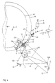
- the coupling gear 11,10,8,7 consists of one Articulation lever 7, which in a pivot joint K with the gripper shaft 4 is coupled.
- the link lever 7 is still with a coupling rod 8 connected in a swivel J.
- the Coupling rod 8 is also with a gear member 10 at the end coupled in a swivel joint B and the transmission link 10 is connected at least to a swivel joint C fixed to the frame.
- With the gear member 10 is a coupling rod is movable 11 connected in a swivel E with a Roller lever 12 is connected.
- the coupling rods 11 and 8 are jointly connected to the gear member 10 mounted in the swivel joint C in the swivel joint B.
- the coupling rod 11 is in turn connected at the end to the roller lever 12 in the swivel joint E (FIG. 3).
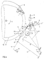
- the transmission link 10 is designed as a ternary link and has the swivel joint B at the end and a swivel joint D at the other end and is pivotably mounted in the swivel joint C fixed to the frame (FIGS. 1, 2, 4-6).
- the gear member 10 is connected as a ternary link in the swivel joint B to one end of the coupling rod 8 and in the swivel joint D to one end of the coupling rod 11 and the coupling rod 11 is coupled at the end to one end of the roller lever 12 in the swivel joint E.
- the roller lever 12 is in the end region of the swivel joint E with an elastic spring system 13 fixed to the frame, preferably a compression spring system, in functional connection and is at the other end in a frame-fixed swivel H pivoted (Fig. 1).
- the roller lever 12 carries a bearing in a pivot joint F.
- Cam roller 14 which with a rotating in the conveying direction 2 Control curve 17 constantly in a mating point 23 in Functional connection is.
- the control curve 17 has at least a gripper closing and a gripper opening area for the movement of the gripper 3 and is preferably on the rotating sheet guide cylinder 19 is arranged.
- the control for locking the pre-gripper 3 (2nd mode of operation) has the analog structure (four-link coupling gear 11,10,8,7; Roller lever 12 with cam roller 14 and Spring system 13; Control curve 17) as the control for opening and closing the pre-gripper 3 in the first operating mode on.
- the roller lever 12 is not directly in the frame Swivel H mounted, but between the frame fixed Swivel H and the roller lever 12 is a gear link 16 arranged.
- the gear member 16 is at the end in the frame-fixed swivel joint H and with the roller lever 12 in a swivel joint G is coupled.
- the transmission link 16 with an actuator mounted on the frame preferably a pneumatic cylinder, gear technology coupled.
- the gear member 16 is at least a frame-fixed stop 20 and / or 21 in functional connection.
- the gear member 16 is preferably arranged with the frame fixed Swivel joint H is formed as a ternary member, which at the end in the swivel joint G with the roller lever 12 and at the end in a swivel joint I with the actuating device 15 is in functional connection.
- the actuator 15 preferably in a swivel joint A fixed to the frame pivoted.
- the actuator 15 preferably in terms of circuitry with a machine control connected.
- adjustable stops 20 and / or 21 arranged fixed to the frame. These stops 20, 21 are preferably in the area of Swivel joints G and / or I arranged.
- the swivel joints B, D, E, G and I are designed to swing freely.
- the swivel joints A, C and H are fixed to the frame.
- the spring system 13 fixed to the frame is preferably arranged parallel to the coupling rod 11 on the roller lever 12. In a further embodiment, the spring system 13 is arranged integrated in the coupling rod 11.
- a first mode of operation for trouble-free sheet transport the driven pre-gripper 5 swings with pre-grippers 3, gripper shaft 4, gripper bar 6, Linkage lever 7 and coupling rod 8 about the swing axis 9.
- the takeover position (Fig. 1 and 2) close the pre-gripper 3 to take over the individual sheet material
- the transfer position (FIG. 4) open the pre-gripper 3, by the roller lever 12 controlled by the control cam 17 (with roller 14) the coupling rods 11 and 8 and the link lever 7 at the pivot points of the pivot joints E, D (if present), B, J and K swivel.
- the transmission link remains 10 in its original position. Closing the Gripper 3 takes place in reverse order.
- the swivel joint B of the pre-gripper relative to the oscillation axis is preferred 9 arranged congruently, i.e. both positions (B, 9) have a common axis, but lie in different levels (Fig. 1 - 4).
- the congruence exists during the trouble-free sheet transport from the Transfer position to the transfer position to the sheet guide cylinder 19th
- the pre-gripper accelerated to machine speed 3 passes in the transfer position (Fig. 4) Sheet material individually to a sheet holding system 18 of the sheet guide cylinder 19.
- the pre-gripper 5 swings after the Transfer position in a run-out position (Fig. 5) and from there back to the takeover position (Fig. 1 - 3). While the actuation device holds the trouble-free sheet transport 15 the gear member 16 in one by at least a stop 21 and / or 22 defined position against the Force of the spring system 13 so that the mating point 23rd constantly by the cam roller 14 and the cam 17 is formed.
- the pre-gripper 5 is controlled in a second operating mode.
- the reported fault causes the actuating device 15 to be activated, for example via the machine control.
- the actuating device 15 pivots the gear member 16 about the axis of the swivel joint H, so that the swivel joint G is moved into the position G 'and, when configured as a ternary member, the swivel joint I is moved into the position I' (FIG. 6).
- the pivoting movement is in turn defined by the adjustable stops 20 and / or 21.
- the roller lever 12 is pivoted in the swivel joint G ', so that the swivel joint E is moved into the position E' (including coupling rod 11) and that Gear member 10 is pivoted about the pivot point of the pivot joint C.
- the swivel joint B which was originally preferably congruent with the swivel axis 9, is moved into the position B 'and - if present - the swivel joint D is moved into the position D'.
- the pivoting movement of the gear member 10 is transmitted to the gripper shaft 4 via the coupling rod 8, swivel joint J 'and articulation lever 7 in the swivel joint K, and the pre-gripper grippers 3 are locked in the respective closing or opening movement that has been initiated, so that there is an engagement between the pre-gripper gripper 3 and the gripper bar 6 Free space 22 is formed.
- the gripper 3 can thus be locked in any machine position, so that sheet transport through the free space 22 is prevented in a process-stable manner.
- the actuator 15 initiated movement of the gear link 16 and the associated movement of the roller lever 12 in Swivel joint G, G 'by maintaining its direction of force Spring system 13 also supported. This results in short switching times with low mass accelerations. Becomes after the fault has been rectified, the pre-gripper is blocked 3 canceled by the actuator 15, so the pre-gripper 5 can be operated again in the first operating mode.
- the control device is summarized in two operating modes executable.
- roller lever 12 In the first mode of operation for trouble-free sheet transport is the roller lever 12 with cam roller 14 at the end mounted in a swivel H fixed to the frame, at the other end is the roller lever 12 with a spring system 13 for permanent Maintenance of a mating point 23 of cam roller 14 and control cam 17 in functional connection and on to the spring system 13 same end of the roller lever 12 in one frame-mounted swivel joint C mounted coupling gear 11,10,8,7 articulated, which with the gripper shaft 4 for Control of the gripper 3 in the swivel joint K in functional connection is.
Landscapes
- Discharge By Other Means (AREA)
- Supply, Installation And Extraction Of Printed Sheets Or Plates (AREA)
- Feeding Of Articles By Means Other Than Belts Or Rollers (AREA)
Applications Claiming Priority (2)
| Application Number | Priority Date | Filing Date | Title |
|---|---|---|---|
| DE10023669A DE10023669C1 (de) | 2000-05-16 | 2000-05-16 | Steuervorrichtung für Vorgreifergreifer eines Vorgreifers in einer Bogenverarbeitungsmaschine |
| DE10023669 | 2000-05-16 |
Publications (3)
| Publication Number | Publication Date |
|---|---|
| EP1155833A2 true EP1155833A2 (fr) | 2001-11-21 |
| EP1155833A3 EP1155833A3 (fr) | 2003-10-01 |
| EP1155833B1 EP1155833B1 (fr) | 2007-09-12 |
Family
ID=7642056
Family Applications (1)
| Application Number | Title | Priority Date | Filing Date |
|---|---|---|---|
| EP01110644A Expired - Lifetime EP1155833B1 (fr) | 2000-05-16 | 2001-05-02 | Dispositif de commande pour une pince des pinces dans une machine de traitement de feuilles |
Country Status (3)
| Country | Link |
|---|---|
| EP (1) | EP1155833B1 (fr) |
| AT (1) | ATE372872T1 (fr) |
| DE (2) | DE10023669C1 (fr) |
Families Citing this family (2)
| Publication number | Priority date | Publication date | Assignee | Title |
|---|---|---|---|---|
| DE10218204A1 (de) | 2002-04-24 | 2003-11-06 | Koenig & Bauer Ag | Vorgreifer mit einem Greifersytem |
| DE10357009B4 (de) * | 2003-12-05 | 2007-09-20 | Man Roland Druckmaschinen Ag | Steuervorrichtung für Greifer eines Vorgreifers in einer Bogenverarbeitungsmaschine |
Family Cites Families (7)
| Publication number | Priority date | Publication date | Assignee | Title |
|---|---|---|---|---|
| DE2224932C2 (de) * | 1972-05-23 | 1974-03-07 | Heidelberger Druckmaschinen Ag, 6900 Heidelberg | Vorgreifersteuerung für Bogenrotationsdruckmaschinen |
| DD229666B1 (de) * | 1984-11-27 | 1988-11-23 | Polygraph Leipzig | Steuereinrichtung fuer greifer eines vorgreifers an bogenverarbeitenden maschinen |
| DE3833645A1 (de) * | 1988-10-04 | 1990-04-12 | Heidelberger Druckmasch Ag | Bogentransfereinrichtung fuer eine druckmaschine |
| DE3922186C2 (de) * | 1989-07-06 | 1994-08-11 | Heidelberger Druckmasch Ag | Kurvenscheiben-Schwingantrieb |
| DE4434623C2 (de) * | 1994-09-28 | 1999-04-29 | Heidelberger Druckmasch Ag | Stellvorrichtung zur Betätigung von Stellgliedern in einer Druckmaschine |
| DE4438757C2 (de) * | 1994-10-29 | 1997-09-11 | Roland Man Druckmasch | Vorgreifer für Bogenrotationsdruckmaschinen |
| DE19543381C2 (de) * | 1995-11-21 | 1999-06-10 | Heidelberger Druckmasch Ag | Greifersteuerung für einen zyklisch schwingend angetriebenen Vorgreifer zum Einzelbogentransport in einer Bogendruckmaschine |
-
2000
- 2000-05-16 DE DE10023669A patent/DE10023669C1/de not_active Expired - Fee Related
-
2001
- 2001-05-02 AT AT01110644T patent/ATE372872T1/de active
- 2001-05-02 DE DE50112985T patent/DE50112985D1/de not_active Expired - Lifetime
- 2001-05-02 EP EP01110644A patent/EP1155833B1/fr not_active Expired - Lifetime
Also Published As
| Publication number | Publication date |
|---|---|
| EP1155833A3 (fr) | 2003-10-01 |
| DE10023669C1 (de) | 2001-06-28 |
| EP1155833B1 (fr) | 2007-09-12 |
| ATE372872T1 (de) | 2007-09-15 |
| DE50112985D1 (de) | 2007-10-25 |
Similar Documents
| Publication | Publication Date | Title |
|---|---|---|
| EP0600183B1 (fr) | Pince pour transporteur pour transporter des produits imprimés à une ou plusieurs feuilles | |
| EP0557680B1 (fr) | Pince pour transporteur pour transporter des produits imprimés à une ou plusieurs feuilles | |
| DE69403579T2 (de) | Papierfördervorrichtung für eine Bogendruckmaschine | |
| DE10150838A1 (de) | Aktuator-Greifersteuerung | |
| DE3736808C2 (fr) | ||
| EP0557679B1 (fr) | Pince pour transporter des produits imprimés à une ou plusieurs feuilles | |
| DE10105374A1 (de) | Ausleger einer Bogen verarbeitenden Maschine | |
| DE10023669C1 (de) | Steuervorrichtung für Vorgreifergreifer eines Vorgreifers in einer Bogenverarbeitungsmaschine | |
| DD282438A5 (de) | Vorrichtung zum zufuehren von bogen an eine bogenverarbeitende maschine, insbesondere druckmaschine | |
| DD229666A1 (de) | Steuereinrichtung der greifer eines vorgreifers an bogenverarbeitenden maschinen | |
| CH410022A (de) | Mechanismus zum Übertragen von Blättern von einem Zuführtisch auf ein drehbares Organ mit Mitteln zum Erfassen der Blätter | |
| EP0361105B1 (fr) | Margeur, notamment pour machines à imprimer des feuilles | |
| DE10129895A1 (de) | Ausleger einer Bogen verarbeitenden Druckmaschine | |
| DE4330392A1 (de) | Schwingender Vorgreifer einer Bogendruckmaschine | |
| DE10345703A1 (de) | Flächige Bedruckstoffe verarbeitende Maschine mit einem mit Nachgreifern ausgerüsteten Ausleger | |
| DE10357009B4 (de) | Steuervorrichtung für Greifer eines Vorgreifers in einer Bogenverarbeitungsmaschine | |
| DE3833645A1 (de) | Bogentransfereinrichtung fuer eine druckmaschine | |
| DE19604562C2 (de) | Vorrichtung zum Leiten von Bogen | |
| DE19947538C1 (de) | Antreibbares Bogenhaltesystem für einen Bogenführungszylinder in einer Rotationsdruckmaschine | |
| EP1620584B1 (fr) | Groupe pince d'une peigneuse | |
| DE69400895T2 (de) | Bogen-wendeeinrichtung für Bogenrotationsdruckmaschinen | |
| DE4339388C2 (de) | Greifersteuerung in Wendetrommeln | |
| DE19744507C2 (de) | Steuereinrichtung für ein Bogentransportsystem in einer Bogenrotationsdruckmaschine | |
| DD134862B1 (de) | Einrichtung zur sperrung der greifer eines vorgreifers | |
| DE10224881B4 (de) | Greifersteuerung für einen zyklisch schwingend angetriebenen Vorgreifer zum Einzelbogentransport in einer bogenverarbeitenden Maschine, insbesondere Bogendruckmaschine |
Legal Events
| Date | Code | Title | Description |
|---|---|---|---|
| PUAI | Public reference made under article 153(3) epc to a published international application that has entered the european phase |
Free format text: ORIGINAL CODE: 0009012 |
|
| AK | Designated contracting states |
Kind code of ref document: A2 Designated state(s): AT BE CH CY DE DK ES FI FR GB GR IE IT LI LU MC NL PT SE TR |
|
| AX | Request for extension of the european patent |
Free format text: AL;LT;LV;MK;RO;SI |
|
| PUAL | Search report despatched |
Free format text: ORIGINAL CODE: 0009013 |
|
| AK | Designated contracting states |
Kind code of ref document: A3 Designated state(s): AT BE CH CY DE DK ES FI FR GB GR IE IT LI LU MC NL PT SE TR |
|
| AX | Request for extension of the european patent |
Extension state: AL LT LV MK RO SI |
|
| 17P | Request for examination filed |
Effective date: 20030823 |
|
| AKX | Designation fees paid |
Designated state(s): AT BE CH CY DE DK ES FI FR GB GR IE IT LI LU MC NL PT SE TR |
|
| GRAP | Despatch of communication of intention to grant a patent |
Free format text: ORIGINAL CODE: EPIDOSNIGR1 |
|
| GRAS | Grant fee paid |
Free format text: ORIGINAL CODE: EPIDOSNIGR3 |
|
| GRAA | (expected) grant |
Free format text: ORIGINAL CODE: 0009210 |
|
| AK | Designated contracting states |
Kind code of ref document: B1 Designated state(s): AT BE CH CY DE DK ES FI FR GB GR IE IT LI LU MC NL PT SE TR |
|
| REG | Reference to a national code |
Ref country code: GB Ref legal event code: FG4D Free format text: NOT ENGLISH |
|
| REG | Reference to a national code |
Ref country code: CH Ref legal event code: EP |
|
| REF | Corresponds to: |
Ref document number: 50112985 Country of ref document: DE Date of ref document: 20071025 Kind code of ref document: P |
|
| REG | Reference to a national code |
Ref country code: IE Ref legal event code: FG4D Free format text: LANGUAGE OF EP DOCUMENT: GERMAN |
|
| PG25 | Lapsed in a contracting state [announced via postgrant information from national office to epo] |
Ref country code: FI Free format text: LAPSE BECAUSE OF FAILURE TO SUBMIT A TRANSLATION OF THE DESCRIPTION OR TO PAY THE FEE WITHIN THE PRESCRIBED TIME-LIMIT Effective date: 20070912 |
|
| NLV1 | Nl: lapsed or annulled due to failure to fulfill the requirements of art. 29p and 29m of the patents act | ||
| GBV | Gb: ep patent (uk) treated as always having been void in accordance with gb section 77(7)/1977 [no translation filed] | ||
| PG25 | Lapsed in a contracting state [announced via postgrant information from national office to epo] |
Ref country code: GR Free format text: LAPSE BECAUSE OF FAILURE TO SUBMIT A TRANSLATION OF THE DESCRIPTION OR TO PAY THE FEE WITHIN THE PRESCRIBED TIME-LIMIT Effective date: 20071213 Ref country code: ES Free format text: LAPSE BECAUSE OF FAILURE TO SUBMIT A TRANSLATION OF THE DESCRIPTION OR TO PAY THE FEE WITHIN THE PRESCRIBED TIME-LIMIT Effective date: 20071223 Ref country code: NL Free format text: LAPSE BECAUSE OF FAILURE TO SUBMIT A TRANSLATION OF THE DESCRIPTION OR TO PAY THE FEE WITHIN THE PRESCRIBED TIME-LIMIT Effective date: 20070912 |
|
| REG | Reference to a national code |
Ref country code: IE Ref legal event code: FD4D |
|
| PG25 | Lapsed in a contracting state [announced via postgrant information from national office to epo] |
Ref country code: GB Free format text: LAPSE BECAUSE OF FAILURE TO SUBMIT A TRANSLATION OF THE DESCRIPTION OR TO PAY THE FEE WITHIN THE PRESCRIBED TIME-LIMIT Effective date: 20070912 Ref country code: PT Free format text: LAPSE BECAUSE OF FAILURE TO SUBMIT A TRANSLATION OF THE DESCRIPTION OR TO PAY THE FEE WITHIN THE PRESCRIBED TIME-LIMIT Effective date: 20080212 |
|
| PG25 | Lapsed in a contracting state [announced via postgrant information from national office to epo] |
Ref country code: SE Free format text: LAPSE BECAUSE OF FAILURE TO SUBMIT A TRANSLATION OF THE DESCRIPTION OR TO PAY THE FEE WITHIN THE PRESCRIBED TIME-LIMIT Effective date: 20071212 |
|
| PLBE | No opposition filed within time limit |
Free format text: ORIGINAL CODE: 0009261 |
|
| STAA | Information on the status of an ep patent application or granted ep patent |
Free format text: STATUS: NO OPPOSITION FILED WITHIN TIME LIMIT |
|
| RAP2 | Party data changed (patent owner data changed or rights of a patent transferred) |
Owner name: MANROLAND AG |
|
| PG25 | Lapsed in a contracting state [announced via postgrant information from national office to epo] |
Ref country code: DK Free format text: LAPSE BECAUSE OF FAILURE TO SUBMIT A TRANSLATION OF THE DESCRIPTION OR TO PAY THE FEE WITHIN THE PRESCRIBED TIME-LIMIT Effective date: 20070912 |
|
| 26N | No opposition filed |
Effective date: 20080613 |
|
| PG25 | Lapsed in a contracting state [announced via postgrant information from national office to epo] |
Ref country code: IE Free format text: LAPSE BECAUSE OF FAILURE TO SUBMIT A TRANSLATION OF THE DESCRIPTION OR TO PAY THE FEE WITHIN THE PRESCRIBED TIME-LIMIT Effective date: 20070912 |
|
| BERE | Be: lapsed |
Owner name: MAN ROLAND DRUCKMASCHINEN A.G. Effective date: 20080531 |
|
| PG25 | Lapsed in a contracting state [announced via postgrant information from national office to epo] |
Ref country code: MC Free format text: LAPSE BECAUSE OF NON-PAYMENT OF DUE FEES Effective date: 20080531 |
|
| REG | Reference to a national code |
Ref country code: CH Ref legal event code: PL |
|
| PG25 | Lapsed in a contracting state [announced via postgrant information from national office to epo] |
Ref country code: CH Free format text: LAPSE BECAUSE OF NON-PAYMENT OF DUE FEES Effective date: 20080531 Ref country code: LI Free format text: LAPSE BECAUSE OF NON-PAYMENT OF DUE FEES Effective date: 20080531 |
|
| PG25 | Lapsed in a contracting state [announced via postgrant information from national office to epo] |
Ref country code: BE Free format text: LAPSE BECAUSE OF NON-PAYMENT OF DUE FEES Effective date: 20080531 |
|
| PG25 | Lapsed in a contracting state [announced via postgrant information from national office to epo] |
Ref country code: CY Free format text: LAPSE BECAUSE OF FAILURE TO SUBMIT A TRANSLATION OF THE DESCRIPTION OR TO PAY THE FEE WITHIN THE PRESCRIBED TIME-LIMIT Effective date: 20070912 |
|
| PG25 | Lapsed in a contracting state [announced via postgrant information from national office to epo] |
Ref country code: LU Free format text: LAPSE BECAUSE OF NON-PAYMENT OF DUE FEES Effective date: 20080502 |
|
| PG25 | Lapsed in a contracting state [announced via postgrant information from national office to epo] |
Ref country code: TR Free format text: LAPSE BECAUSE OF FAILURE TO SUBMIT A TRANSLATION OF THE DESCRIPTION OR TO PAY THE FEE WITHIN THE PRESCRIBED TIME-LIMIT Effective date: 20070912 |
|
| PG25 | Lapsed in a contracting state [announced via postgrant information from national office to epo] |
Ref country code: IT Free format text: LAPSE BECAUSE OF NON-PAYMENT OF DUE FEES Effective date: 20080531 |
|
| PGFP | Annual fee paid to national office [announced via postgrant information from national office to epo] |
Ref country code: AT Payment date: 20110512 Year of fee payment: 11 |
|
| PGFP | Annual fee paid to national office [announced via postgrant information from national office to epo] |
Ref country code: DE Payment date: 20110520 Year of fee payment: 11 |
|
| REG | Reference to a national code |
Ref country code: DE Ref legal event code: R081 Ref document number: 50112985 Country of ref document: DE Owner name: MANROLAND SHEETFED GMBH, DE Free format text: FORMER OWNER: MANROLAND AG, 63075 OFFENBACH, DE Effective date: 20120509 |
|
| REG | Reference to a national code |
Ref country code: AT Ref legal event code: MM01 Ref document number: 372872 Country of ref document: AT Kind code of ref document: T Effective date: 20120502 |
|
| PG25 | Lapsed in a contracting state [announced via postgrant information from national office to epo] |
Ref country code: AT Free format text: LAPSE BECAUSE OF NON-PAYMENT OF DUE FEES Effective date: 20120502 |
|
| REG | Reference to a national code |
Ref country code: DE Ref legal event code: R119 Ref document number: 50112985 Country of ref document: DE Effective date: 20121201 |
|
| PG25 | Lapsed in a contracting state [announced via postgrant information from national office to epo] |
Ref country code: DE Free format text: LAPSE BECAUSE OF NON-PAYMENT OF DUE FEES Effective date: 20121201 |
|
| PG25 | Lapsed in a contracting state [announced via postgrant information from national office to epo] |
Ref country code: FR Free format text: LAPSE BECAUSE OF FAILURE TO SUBMIT A TRANSLATION OF THE DESCRIPTION OR TO PAY THE FEE WITHIN THE PRESCRIBED TIME-LIMIT Effective date: 20070912 |