EP1155837A2 - Machine à imprimer avec un cylindre porte-plaque portant plusieurs plaques - Google Patents
Machine à imprimer avec un cylindre porte-plaque portant plusieurs plaques Download PDFInfo
- Publication number
- EP1155837A2 EP1155837A2 EP01110022A EP01110022A EP1155837A2 EP 1155837 A2 EP1155837 A2 EP 1155837A2 EP 01110022 A EP01110022 A EP 01110022A EP 01110022 A EP01110022 A EP 01110022A EP 1155837 A2 EP1155837 A2 EP 1155837A2
- Authority
- EP
- European Patent Office
- Prior art keywords
- plate
- cylinder
- pressure
- clamping device
- pressure plate
- Prior art date
- Legal status (The legal status is an assumption and is not a legal conclusion. Google has not performed a legal analysis and makes no representation as to the accuracy of the status listed.)
- Granted
Links
Images


Classifications
-
- B—PERFORMING OPERATIONS; TRANSPORTING
- B41—PRINTING; LINING MACHINES; TYPEWRITERS; STAMPS
- B41F—PRINTING MACHINES OR PRESSES
- B41F13/00—Common details of rotary presses or machines
- B41F13/08—Cylinders
- B41F13/10—Forme cylinders
- B41F13/12—Registering devices
- B41F13/16—Registering devices with means for displacing the printing formes on the cylinders
-
- B—PERFORMING OPERATIONS; TRANSPORTING
- B41—PRINTING; LINING MACHINES; TYPEWRITERS; STAMPS
- B41F—PRINTING MACHINES OR PRESSES
- B41F27/00—Devices for attaching printing elements or formes to supports
- B41F27/12—Devices for attaching printing elements or formes to supports for attaching flexible printing formes
- B41F27/1262—Devices for attaching printing elements or formes to supports for attaching flexible printing formes without tensioning means
-
- B—PERFORMING OPERATIONS; TRANSPORTING
- B41—PRINTING; LINING MACHINES; TYPEWRITERS; STAMPS
- B41P—INDEXING SCHEME RELATING TO PRINTING, LINING MACHINES, TYPEWRITERS, AND TO STAMPS
- B41P2227/00—Mounting or handling printing plates; Forming printing surfaces in situ
- B41P2227/10—Attaching several printing plates on one cylinder
- B41P2227/11—Attaching several printing plates on one cylinder in axial direction
Definitions
- the present invention relates to a printing press, in particular a web-fed offset printing press, with a first and a second pressure plate carrying Plate cylinder according to the preamble of claim 1.
- An endless web of material for example paper, is printed in printing machines.
- the plate cylinder of the printing press carries a flat printing plate, for example one Offset printing plate, which is clamped on the cylinder in a known manner or in some other way Way is locked.
- An image to be printed is created by color that is different from the Printing plate is transferred to the paper.
- the plate transfers in offset printing machines first paint on a rubber blanket and then on the paper.
- US 5,248,093 discloses a single-plate plate cylinder with a Locking mechanism that allows the individual plate to be attached.
- US 5,678,487 discloses a locking mechanism which in connection with a Pressure bar for attaching a single plate to a single-plate plate cylinder is used.
- each printing plate should be able to be aligned axially, i.e. correctly positioned with respect to the plate cylinder and each of the other printing plates his.
- the Align the plate by moving the plate cylinder with respect to the substrate becomes.
- the problem of an independent register setting is not taken into account here.
- An additional or alternative object of the present The invention is to provide a printing machine with a multi-plate cylinder, which an independent register setting of each individual plate enables.
- Another one an alternative or additional object of the present invention is to provide a simple process for applying printing plates to a multi-plate plate cylinder.
- a printing press comprises a plurality of printing plates, for example two, three, four or more printing plates, supporting plate cylinders (hereinafter also called multi-plate plate cylinder), which has a cylinder body an outer surface and a plate clamp, e.g. B. a clamping rail or Terminal block, which is clamped into a retracted or retracted Position and an extended position that releases the plate ends, wherein the clamping device preferably radially over in the extended position the outer surface of the plate cylinder extends out and in the retracted position for fixing the first and second pressure plates on the outer peripheral surface of the Plate cylinder is used.
- multi-plate plate cylinder which has a cylinder body an outer surface and a plate clamp, e.g. B. a clamping rail or Terminal block, which is clamped into a retracted or retracted Position and an extended position that releases the plate ends, wherein the clamping device preferably radially over in the extended position the outer surface of the plate cylinder extends out and in the re
- the press also includes a pressure bar next to the Clamping device, wherein the pressure bar for at least a first segment Press and hold the first printing plate on the plate cylinder and a second one Segment for pressing and holding the second printing plate on the plate cylinder includes, and the first segment is movable independently of the second segment.
- a single plate of the multi-plate cylinder can be removed if one Segment of the pressure bar is retracted.
- the other plates can continue from the other segments are held in a holding position or position can be positioned. This allows you to share with just a single Clamping strip for the plate cylinder the plates are completely independent of each other can be removed, reducing the complexity and cost of the multi-plate plate cylinder be significantly reduced since there is no separate clamping device for each the printing plates is needed.
- the plate cylinder preferably comprises at least one of the individual printing plates each assigned register pin, so that the pressure plate in an axial direction can be aligned correctly.
- the pins on the cylinder can advantageously be adjusted manually from the outside, when the clamping device is in the extended position.
- the plate cylinder can advantageously also have at least one spring element Clamping a front and / or rear edge of a pressure plate include.
- the pressure bar can be a plurality independently of one another, preferably pneumatically Actuate piston to move the different segments.
- the Pressure bar preferably acts on the rear edge of the pressure plate on the Clamping device is held.
- the front edge of the pressure plate is preferably on held the plate cylinder body.
- movable multi-plate plate cylinder having a common terminal strip carries at least a first pressure plate and a second pressure plate, following Method steps: contacting the first printing plate with an assigned first Segment of the pressure bar when the common terminal block in the extended, i.e. H. the non-clamping position, while the second pressure plate is assigned by the second segment of the pressure bar is not contacted; Moving the common Terminal block in the retracted position, i.e. in a position in which the Pressure plate ends clamped and the pressure plate is attached to the plate cylinder and one end of the second pressure plate is released; as well as removing the second Pressure plate from the plate cylinder.
- the first pressure plate can not be from Loosen the plate cylinder and is held in register while the Clamping device is in the extended position.
- the second Printing plate can be removed independently of the first printing plate, even if both plates have a common clamping device.
- the present method can also move all segments of the pressure bar away from the cylinder surface after moving the common clamp include.
- Removing the pressure plate can cause the plate cylinder to rotate about one Include revolution.
- the second edge or the second end of the second pressure plate can then be removed.
- the second edge can be removed by returning it the first segment to touch the first pressure plate and extend the Clamping device can be supported in such a way that the second end of the pressure plate through the one that preferably moves radially out of the cylinder surface Clamping device is deformed.
- a register pin assigned to the second plate can then be moved manually can be set, for example by axially moving the register pin.
- a new or the same second printing plate can be attached to the plate cylinder.
- the second plate can be attached by inserting a leading edge of the pressure plate into one in the Periphery of the plate cylinder formed slot is inserted.
- the leading edge can to be clamped in the slot with the second segment, and the clamping device can be moved to its retracted position, creating the leading edge of the second Pressure plate and the first pressure plate can be locked. All segments of the pressure bar are then moved away from the cylinder and the cylinder is about one Turned so that the new second plate wraps around the cylinder.
- the Clamping device is then moved to the extended position, that of the first Pressure plate segment associated pressure plate holds the first pressure plate.
- segment preferably presses in the rear edge of the second plate the associated slot of the clamping device and then fixes the pressure plate in the area of the rear edge on the plate cylinder, so that the rear edge of the Clamping device can be held, which is retracted for this purpose. Both the first as well as the second plate are thereby held. All segments of the pressure bar are then moved away from the printing plates and the printing press is ready for Print with a new or realigned second plate.
- the plate cylinder preferably carries four plates with it, each independently are interchangeable. For example, if the second plate is replaced the third and fourth plates are made in the same way as the first plate held.
- Lane 1 shows an offset printing machine 10 for printing on a web 1 made of material such as for example paper.
- the web 1 passes through one of two blanket cylinders 2, 12 shaped gap.
- On the blanket cylinders are, for example, axially removable sleeve-shaped rubber blankets applied.
- a first multi-plate plate cylinder 3 contacts the blanket cylinder 2
- a second multi-plate plate cylinder 13 contacts the blanket cylinder 12.
- Lane 1 can have a number of independent lanes include axially adjacent to each other between the blanket cylinders, for. B. in Are spaced from each other and can be printed on both sides.
- the plates on plate cylinder 3 can therefore receive color from an inking unit, the image on the blanket cylinder 2 and is transferred from this to a first side of the web 1 and the plates on the plate cylinder 13 over the blanket cylinder 12 an image apply a second side of web 1.
- the plate cylinder 3 has a common one Clamping device 5 for fastening all plates of the plate cylinder 3, and Plate cylinder 13 has a common clamping device 15.
- a segmented Pressure bar 4 is used for pressing or for pushing in and holding the plates in an axially extending gap 6 in the outer surface of the plate cylinder 3, and one segmented pressure bar 14 is used for pressing, d. H. Push in and hold Plates in an axially extending gap 16 of the plate cylinder 13.
- Fig. 2 shows a perspective view of the plate cylinder 3 with an axially extending between four different plate areas 3a, 3b, 3c and 3d common clamping device 5.
- the plate 20a and the plate 20b can in the Plate areas 3a and 3b are attached. Two more plates can also be used for the Sections 3c and 3d are provided.
- the plate 20a and the plate 20b can be axial through the interaction of the register holes 22a, 22b with that on the Clamping device 5 located register pin are aligned as below is described.
- the plate 20a has a leading edge 23 and a trailing edge 24 which are preferably curved.
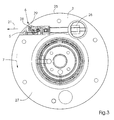
- FIG. 3 shows a cross-sectional or side view of the cylinder 3, which has an outer surface 25 having.
- the clamping device 5 is between a retracted position shown and an extended position, which can be done by moving the clamping device 5 is reached in a direction 21.
- A can be used to move the clamping device 5
- Actuating device 26 may be provided. So that the plates are attached (clamped) or can be solved, the clamping device 5 by moving in the direction of Arrow 21, as indicated in Fig. 3, from a retracted position in one extended position moved.
- the plate 20a and the plate 20b as well as the plates for the sections 3c and 3d can therefore be attached to the cylinder 3 by the clamping device 5 in an extended Position is moved so that the clamping device 5 radially over the surface 25 of the Cylinder 3 protrudes.
- the leading edges or leading edges of the plates 20a, 20b can therefore be positioned in such a way that they are preferably at an angle arranged section 29 of the cylinder body 27 of cylinder 3 in interaction stand, either with or without the help of the pressure bar 4, as shown in Fig. 2.
- the Clamping device 5 can then be retracted (clamping position) and the plate cylinder in Direction of arrow 7 are rotated so that the plates 20a, 20b around the Place plate cylinder 3.
- the pressure bar 4 can the rear edges of the plates on the cylinder 3rd press on so that the rear edges with the angled section 28 of the terminal strip 5 in Can interact.
- This allows segment 4A and segment 4B to Pressure bar 4 to move on the cylinder 3, as well as segment 4C and segment 4D, so that the trailing edges of the four plates in the gap 6 in the plate cylinder 3rd can be pushed in.
- the clamping device 5 is then retracted (Clamping position) so that all four plates are attached.
- the Clamping device preferably has a register pin for each plate.
- the clamping device has 5 register pins 30A, 30B, which for a correct ensure the axial register position of the plates.
- the register pins 30A, 30B are on the clamping device 5, but extend into the gap, so that they with the perforations 22a and 22b in the front edge of the plates 20a, 20b are still interacting, such as is shown in Fig. 2.
- the rear edges of the slots can also be used Register perforations are provided or with perforations that are even larger than that Holes 22a and 22b.
- the register pins 30A, 30B, and those for sections 3c and 3d, can be manually can be adjusted when the clamping device 5 is extended by the pins axially be moved.
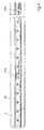
- Fig. 5 shows a cross section of the strip 5 at the level of the register pin 30A, as by the Line A-A in Fig. 4 is indicated.
- a screw 32 with an external thread can be used in one Internally threaded hole 31 of the register pin 30A can be placed.
- the screw 32 can be tightened or loosened, for example with an Allen key, around the Register pin 30a preferably frictionally on a (friction) element 33 of the strip 5 fasten. This allows an operator to release the register pin 30A to make the pin can be moved axially during manual adjustment and after the end Tighten the setting process again.
- Fig. 6 shows a cross section of the strip 5 along the section B-B of Fig. 4.
- a spring 34 can help hold the trailing edge of the panels.
- the pressure bar 4 has a housing 40, a piston 41 and a clamping piece 42 which is fixed to a Terminal segment 4A is connected.
- the pressure bar 4 has one Large number of segments 4A and 4B, as well as two further segments.
- Each of the Segments 4A, 4B are connected to a plurality of pistons 41, the pistons for each segment can preferably be operated independently, for example by four Air lines 46. Therefore, the pistons for each segment can be supplied with compressed air one of the lines 46 is provided to be moved towards the cylinder 3.
- Springs 44 can cause segment 4A to move away from cylinder 3. This can each of the segments 4A, 4B, 4C, 4D are operated independently.
- Printing machine 10 is preferably operated as follows, if not all plates to be replaced or realigned.
- the panels are on sections 3a, 3b, 3c, 3d, attached.
- Section 3c may need to be realigned or that a plate change is desired for this section.
- the clamping device 5 is moved to an extended position while the segments 4A, 4B and 4D the pressure bar 4, the respective pressure plates against the clamping device 5, or in Push the area of the clamping device 5 against the plate cylinder 3.
- the rear edge of the plate arranged on section 3c which is not held by segment 4C, because this remains retracted, detaches from the strip 5.
- the strip 5 is then retracted (Clamping position), so that the panels in sections 3a, 3b and 3d as well as the Front edge of the plate can be clamped in section 3c.
- the segments 4A, 4B and 4D of the pressure bar 4 are retracted.
- the cylinder 3 is then the opposite Direction 7 rotated so that the rear edge of the plate appears.
- the clamping segments 4A, 4B and 4D are reactivated and the bar 5 moved to the extended position.
- the front edge of the plate for section 3c can then be removed.
- the front edge of the new printing plate is inserted into the Slot 6 inserted while the bar 5 is in the extended position, the leading edge interacting with the register pin to make a correct one Ensure positioning.
- the segment 4C of the pressure bar 4 can do this Support the insertion process, or the insertion can be carried out manually.
- the Clamping device 5 is then retracted around the leading edge and the other panels to clamp, and all segments of the pressure bar 4 are following it retracted. Then the cylinder 3 is rotated in the direction 7, so that the plate wraps around cylinder 3.
- the segments 4A, 4B and 4D of the pressure bar 4 are activated again while the clamping device 5 moves into the extended position so that the plates on sections 3a, 3b and 3d do not come loose.
Landscapes
- Engineering & Computer Science (AREA)
- Mechanical Engineering (AREA)
- Supply, Installation And Extraction Of Printed Sheets Or Plates (AREA)
- Rotary Presses (AREA)
Applications Claiming Priority (2)
| Application Number | Priority Date | Filing Date | Title |
|---|---|---|---|
| US572361 | 1984-01-20 | ||
| US09/572,361 US6439117B1 (en) | 2000-05-17 | 2000-05-17 | Printing press with multi-plate plate cylinder |
Publications (3)
| Publication Number | Publication Date |
|---|---|
| EP1155837A2 true EP1155837A2 (fr) | 2001-11-21 |
| EP1155837A3 EP1155837A3 (fr) | 2004-07-07 |
| EP1155837B1 EP1155837B1 (fr) | 2011-02-16 |
Family
ID=24287450
Family Applications (1)
| Application Number | Title | Priority Date | Filing Date |
|---|---|---|---|
| EP01110022A Expired - Lifetime EP1155837B1 (fr) | 2000-05-17 | 2001-04-26 | Machine à imprimer avec un cylindre porte-plaque portant plusieurs plaques |
Country Status (4)
| Country | Link |
|---|---|
| US (2) | US6439117B1 (fr) |
| EP (1) | EP1155837B1 (fr) |
| JP (1) | JP4603722B2 (fr) |
| DE (2) | DE10120134A1 (fr) |
Cited By (3)
| Publication number | Priority date | Publication date | Assignee | Title |
|---|---|---|---|---|
| EP1256449A1 (fr) * | 2001-05-07 | 2002-11-13 | Heidelberger Druckmaschinen Aktiengesellschaft | Imprimante avec un cylindre de plaque et avec une barre d'insertion |
| EP1481803A1 (fr) | 2003-05-27 | 2004-12-01 | MAN Roland Druckmaschinen AG | Cylindre porte-plaque pour une machine d'impression |
| EP2047993A1 (fr) * | 2007-10-10 | 2009-04-15 | WIFAG Maschinenfabrik AG | Cylindre d'impression supportant par friction un dispositif de registre |
Families Citing this family (14)
| Publication number | Priority date | Publication date | Assignee | Title |
|---|---|---|---|---|
| DE10238177B3 (de) * | 2002-08-21 | 2004-02-05 | Koenig & Bauer Ag | Vorrichtung zum Andrücken eines Aufzugs an einen Zylinder einer Druckmaschine mit Hilfe von in Umfangsrichtung des Zylinders voneinander beabstandeten ersten und zweiten Wälzelementen |
| DE20221647U1 (de) * | 2001-10-05 | 2006-09-28 | Koenig & Bauer Ag | Rollenrotationsdruckmaschine |
| DE10238179B3 (de) * | 2002-08-21 | 2004-01-08 | Koenig & Bauer Ag | Vorrichtung zum Führen eines Aufzugs an einen Zylinder einer Druckmaschine |
| DE10311285A1 (de) | 2003-03-14 | 2004-09-30 | Koenig & Bauer Ag | Druckwerke einer Druckmaschine mit mindestens einem Fromzylinder |
| US6810808B1 (en) | 2003-06-02 | 2004-11-02 | Heidelberger Druckmaschinen Ag | Plate cylinder with register pin adjustment device and method of axially adjusting printing plate |
| DE102004023434A1 (de) * | 2004-05-10 | 2005-12-08 | Maschinenfabrik Wifag | Rotationsdruckmaschine mit Saugvorrichtung, Saugvorrichtung und Verfahren zum Wechseln einer Druckform |
| DE102004023008A1 (de) * | 2004-05-10 | 2005-12-08 | Maschinenfabrik Wifag | Spann- und Registereinrichtung |
| WO2006104830A2 (fr) | 2005-03-30 | 2006-10-05 | Goss International Americas, Inc. | Presse a imprimer offset sur papier sans fin pourvue d'une lame plieuse articulee |
| DE102005017181A1 (de) * | 2005-04-13 | 2006-10-19 | Man Roland Druckmaschinen Ag | Druckeinheit einer Rollenrotationsdruckmaschine |
| EP1790472A3 (fr) * | 2005-11-02 | 2008-05-07 | Goss Systemes Graphiques Nantes | Presse d'impression à actionneurs de verrouillage de plaques portés par le bâti |
| FR2892660B1 (fr) | 2005-11-02 | 2012-05-25 | Goss Systemes Graphiques Nantes | Presse d'impression a actionneurs de verrouillage de plaques portes par le bati. |
| DE102006012288A1 (de) * | 2006-03-17 | 2007-09-20 | Man Roland Druckmaschinen Ag | Druckwerkzylinder einer Druckmaschine |
| DE102007006705A1 (de) * | 2007-02-10 | 2008-08-14 | Man Roland Druckmaschinen Ag | Verfahren zum Beschichten eines Druckmaschinenzylinders |
| FR2986180B1 (fr) * | 2012-01-27 | 2014-12-19 | Goss Internat France | Dispositif de chargement des plaques d'impression sur un cylindre porte-plaque d'une presse rotative offset |
Family Cites Families (15)
| Publication number | Priority date | Publication date | Assignee | Title |
|---|---|---|---|---|
| US2708875A (en) * | 1952-05-31 | 1955-05-24 | Hoe & Co R | Printing plate cylinder |
| US2768578A (en) * | 1953-10-08 | 1956-10-30 | Tribune Company | Lock-up mechanism for dry offset printing plates |
| GB1065727A (en) * | 1963-11-28 | 1967-04-19 | Harris Intertype Corp | Improvements in or relating to printing presses |
| US3335663A (en) * | 1964-08-12 | 1967-08-15 | Miehle Goss Dexter Inc | Plate lockup for reversible plate cylinder |
| US3858512A (en) * | 1973-03-22 | 1975-01-07 | Roland Offsetmaschf | Lock-up mechanism for flexible printing plates providing improved reference adjustment |
| US5016531A (en) * | 1989-01-19 | 1991-05-21 | Hercules, Incorporated | Double truck printing registration system for a rotary printing press |
| JP2651720B2 (ja) * | 1989-03-18 | 1997-09-10 | 株式会社東京機械製作所 | 輪転印刷機におけるスポット印刷方法及びスポット印刷用ブランケット胴 |
| JP2550001B2 (ja) * | 1991-08-08 | 1996-10-30 | 株式会社東京機械製作所 | 刷版装着装置 |
| DE4132805C2 (de) * | 1991-10-02 | 1995-05-04 | Koenig & Bauer Ag | Seitenregister-Einstellvorrichtung für Druckplatten |
| US5284093A (en) | 1993-02-24 | 1994-02-08 | Heidelberg Harris Inc. | Plate cylinder with semi-automatic plate lock up |
| WO1995019263A1 (fr) * | 1994-01-17 | 1995-07-20 | Koenig & Bauer-Albert Aktiengesellschaft | Dispositif de montage, de demontage et de transport d'objets courbes faciles a plier et pourvus de rebords de suspension |
| JPH07241976A (ja) * | 1994-03-04 | 1995-09-19 | Seiken Graphics Kk | 版胴への印刷版の取付け位置の微調整構造 |
| US5678487A (en) | 1995-11-15 | 1997-10-21 | Heidelberg Harris Inc. | Apparatus for mounting flexible plates in a printing unit |
| DE19620997C2 (de) * | 1996-05-24 | 1998-03-26 | Koenig & Bauer Albert Ag | Verfahren und Vorrichtung zum axialen Positionieren einer Druckplatte |
| DE19803809A1 (de) * | 1998-01-31 | 1999-08-05 | Roland Man Druckmasch | Offsetdruckwerk |
-
2000
- 2000-05-17 US US09/572,361 patent/US6439117B1/en not_active Expired - Fee Related
-
2001
- 2001-04-25 DE DE10120134A patent/DE10120134A1/de not_active Withdrawn
- 2001-04-26 DE DE50115796T patent/DE50115796D1/de not_active Expired - Lifetime
- 2001-04-26 EP EP01110022A patent/EP1155837B1/fr not_active Expired - Lifetime
- 2001-05-14 JP JP2001143988A patent/JP4603722B2/ja not_active Expired - Fee Related
-
2002
- 2002-06-10 US US10/165,906 patent/US6615731B2/en not_active Expired - Fee Related
Cited By (7)
| Publication number | Priority date | Publication date | Assignee | Title |
|---|---|---|---|---|
| EP1256449A1 (fr) * | 2001-05-07 | 2002-11-13 | Heidelberger Druckmaschinen Aktiengesellschaft | Imprimante avec un cylindre de plaque et avec une barre d'insertion |
| US6595135B2 (en) | 2001-05-07 | 2003-07-22 | Heidelberger Druckmaschinen Ag | Printing unit with automatically moveable tail tucker bar |
| EP1481803A1 (fr) | 2003-05-27 | 2004-12-01 | MAN Roland Druckmaschinen AG | Cylindre porte-plaque pour une machine d'impression |
| DE10324330A1 (de) * | 2003-05-27 | 2004-12-30 | Man Roland Druckmaschinen Ag | Plattenzylinder einer Druckmaschine |
| US6901858B2 (en) | 2003-05-27 | 2005-06-07 | Man Roland Druckmaschinen Ag | Plate cylinder of a printing press |
| CN100421937C (zh) * | 2003-05-27 | 2008-10-01 | 曼.罗兰.德鲁克马辛伦公司 | 印刷机的印版滚筒 |
| EP2047993A1 (fr) * | 2007-10-10 | 2009-04-15 | WIFAG Maschinenfabrik AG | Cylindre d'impression supportant par friction un dispositif de registre |
Also Published As
| Publication number | Publication date |
|---|---|
| JP2001353846A (ja) | 2001-12-25 |
| US6615731B2 (en) | 2003-09-09 |
| US20020148373A1 (en) | 2002-10-17 |
| JP4603722B2 (ja) | 2010-12-22 |
| EP1155837A3 (fr) | 2004-07-07 |
| EP1155837B1 (fr) | 2011-02-16 |
| US6439117B1 (en) | 2002-08-27 |
| DE50115796D1 (de) | 2011-03-31 |
| DE10120134A1 (de) | 2001-11-22 |
Similar Documents
| Publication | Publication Date | Title |
|---|---|---|
| EP1155837B1 (fr) | Machine à imprimer avec un cylindre porte-plaque portant plusieurs plaques | |
| EP0085751B1 (fr) | Machine rotative d'impression offset de feuilles | |
| DE4335140C1 (de) | Vorrichtung zum Befestigen einer biegsamen Druckplatte | |
| EP1157855B1 (fr) | Manchon à base de caoutchouc, notamment pour machines rotatives offset | |
| EP0579017A1 (fr) | Dispositif pour tendre une plaque d'impression sur un cylindre de plaque | |
| DE4327646C5 (de) | Breiten-Einstellverfahren für eine Papierbahn sowie damit ausgerüstete lithographische Rotationspresse | |
| EP1068077A1 (fr) | Dispositif de perforage, rainage ou decoupage destine a des rotatives a feuilles pour impression en polychromie | |
| EP0154843A2 (fr) | Dispositif de tension des plaques d'impression | |
| EP1413433A1 (fr) | Unité d'impression d'une machine rotative d'impression pour journaux | |
| DE10066162B4 (de) | Druckwerk einer Rotationsdruckmaschine | |
| EP1155838B1 (fr) | Cylindre porte-plaque et positionneur extérieur de plaque | |
| EP0995596B1 (fr) | Dispositif et procédé pour la mise en oeuvre d'un changement de plaques en marche | |
| EP1013467B1 (fr) | Plaque d'impression pour imprimante offset rotative | |
| DE3508699A1 (de) | Hoehenverstellbare greiferauflagen fuer wendetrommelgreifer in wendetrommeln von schoen- und widerdruckmaschinen | |
| EP0727311A1 (fr) | Dispositif pour échanger des plaques d'impression | |
| EP0755785B1 (fr) | Dispositif de fixation d'une plaque avec réduction de la zône sans pression | |
| DE102005002847A1 (de) | Rollenrotationsdruckmaschine | |
| CH702383B1 (de) | Druckwerk einer Druckmaschine und Verfahren zum Wechseln mindestens einer Druckplatte an einem solchen Druckwerk. | |
| EP0592856A1 (fr) | Dispositif de serrage pour fixer une forme d'impression flexible à la surface d'un cylindre | |
| DE102017201161B4 (de) | Verfahren zum Aufziehen einer Platte auf einen Zylinder einer Druckmaschine und eine Vorrichtung zum Aufziehen einer Platte in einer Druckmaschine | |
| DE102019120263A1 (de) | Druckwerk einer Rotationsdruckmaschine | |
| EP1348550A2 (fr) | Cylindre avec un dispositif de fixation pour une couverture supérieure flexible dans une machine de traitement | |
| DE2757552C2 (de) | Formzylinder für eine Rotationsdruckmaschine | |
| EP0732204A1 (fr) | Dispositif pour enlever une plaque d'impression d'un cylindre | |
| AT382822B (de) | Vorrichtung zum halten des unteren aufzuges eines zweilagigen aufzuges auf der mantelflaeche eines druckzylinders in druckmaschinen |
Legal Events
| Date | Code | Title | Description |
|---|---|---|---|
| PUAI | Public reference made under article 153(3) epc to a published international application that has entered the european phase |
Free format text: ORIGINAL CODE: 0009012 |
|
| AK | Designated contracting states |
Kind code of ref document: A2 Designated state(s): AT BE CH CY DE DK ES FI FR GB GR IE IT LI LU MC NL PT SE TR |
|
| AX | Request for extension of the european patent |
Free format text: AL;LT;LV;MK;RO;SI |
|
| PUAL | Search report despatched |
Free format text: ORIGINAL CODE: 0009013 |
|
| AK | Designated contracting states |
Kind code of ref document: A3 Designated state(s): AT BE CH CY DE DK ES FI FR GB GR IE IT LI LU MC NL PT SE TR |
|
| AX | Request for extension of the european patent |
Extension state: AL LT LV MK RO SI |
|
| RIC1 | Information provided on ipc code assigned before grant |
Ipc: 7B 41F 13/16 B Ipc: 7B 41F 27/00 B Ipc: 7B 41F 27/12 A |
|
| RAP1 | Party data changed (applicant data changed or rights of an application transferred) |
Owner name: GOSS INTERNATIONAL AMERICAS, INC. |
|
| 17P | Request for examination filed |
Effective date: 20041120 |
|
| AKX | Designation fees paid |
Designated state(s): CH DE FR GB LI |
|
| 111Z | Information provided on other rights and legal means of execution |
Free format text: CH DE FR GB Effective date: 20091012 |
|
| GRAP | Despatch of communication of intention to grant a patent |
Free format text: ORIGINAL CODE: EPIDOSNIGR1 |
|
| GRAS | Grant fee paid |
Free format text: ORIGINAL CODE: EPIDOSNIGR3 |
|
| GRAA | (expected) grant |
Free format text: ORIGINAL CODE: 0009210 |
|
| AK | Designated contracting states |
Kind code of ref document: B1 Designated state(s): CH DE FR GB LI |
|
| REG | Reference to a national code |
Ref country code: GB Ref legal event code: FG4D Free format text: NOT ENGLISH |
|
| REG | Reference to a national code |
Ref country code: CH Ref legal event code: EP |
|
| REF | Corresponds to: |
Ref document number: 50115796 Country of ref document: DE Date of ref document: 20110331 Kind code of ref document: P |
|
| REG | Reference to a national code |
Ref country code: DE Ref legal event code: R096 Ref document number: 50115796 Country of ref document: DE Effective date: 20110331 |
|
| PGFP | Annual fee paid to national office [announced via postgrant information from national office to epo] |
Ref country code: CH Payment date: 20110411 Year of fee payment: 11 |
|
| PGFP | Annual fee paid to national office [announced via postgrant information from national office to epo] |
Ref country code: GB Payment date: 20110426 Year of fee payment: 11 |
|
| PLBE | No opposition filed within time limit |
Free format text: ORIGINAL CODE: 0009261 |
|
| STAA | Information on the status of an ep patent application or granted ep patent |
Free format text: STATUS: NO OPPOSITION FILED WITHIN TIME LIMIT |
|
| 26N | No opposition filed |
Effective date: 20111117 |
|
| REG | Reference to a national code |
Ref country code: DE Ref legal event code: R097 Ref document number: 50115796 Country of ref document: DE Effective date: 20111117 |
|
| REG | Reference to a national code |
Ref country code: CH Ref legal event code: PL |
|
| GBPC | Gb: european patent ceased through non-payment of renewal fee |
Effective date: 20120426 |
|
| PG25 | Lapsed in a contracting state [announced via postgrant information from national office to epo] |
Ref country code: LI Free format text: LAPSE BECAUSE OF NON-PAYMENT OF DUE FEES Effective date: 20120430 Ref country code: CH Free format text: LAPSE BECAUSE OF NON-PAYMENT OF DUE FEES Effective date: 20120430 Ref country code: GB Free format text: LAPSE BECAUSE OF NON-PAYMENT OF DUE FEES Effective date: 20120426 |
|
| PGFP | Annual fee paid to national office [announced via postgrant information from national office to epo] |
Ref country code: DE Payment date: 20130429 Year of fee payment: 13 |
|
| PGFP | Annual fee paid to national office [announced via postgrant information from national office to epo] |
Ref country code: FR Payment date: 20130506 Year of fee payment: 13 |
|
| REG | Reference to a national code |
Ref country code: DE Ref legal event code: R119 Ref document number: 50115796 Country of ref document: DE |
|
| REG | Reference to a national code |
Ref country code: DE Ref legal event code: R119 Ref document number: 50115796 Country of ref document: DE Effective date: 20141101 |
|
| REG | Reference to a national code |
Ref country code: FR Ref legal event code: ST Effective date: 20141231 |
|
| PG25 | Lapsed in a contracting state [announced via postgrant information from national office to epo] |
Ref country code: DE Free format text: LAPSE BECAUSE OF NON-PAYMENT OF DUE FEES Effective date: 20141101 |
|
| PG25 | Lapsed in a contracting state [announced via postgrant information from national office to epo] |
Ref country code: FR Free format text: LAPSE BECAUSE OF NON-PAYMENT OF DUE FEES Effective date: 20140430 |