EP1155893A2 - Dispositif d'absorption de couple d'un moteur à combustion interne - Google Patents
Dispositif d'absorption de couple d'un moteur à combustion interne Download PDFInfo
- Publication number
- EP1155893A2 EP1155893A2 EP01107993A EP01107993A EP1155893A2 EP 1155893 A2 EP1155893 A2 EP 1155893A2 EP 01107993 A EP01107993 A EP 01107993A EP 01107993 A EP01107993 A EP 01107993A EP 1155893 A2 EP1155893 A2 EP 1155893A2
- Authority
- EP
- European Patent Office
- Prior art keywords
- support
- strut
- bracket
- bearing
- arm
- Prior art date
- Legal status (The legal status is an assumption and is not a legal conclusion. Google has not performed a legal analysis and makes no representation as to the accuracy of the status listed.)
- Granted
Links
Images


Classifications
-
- B—PERFORMING OPERATIONS; TRANSPORTING
- B60—VEHICLES IN GENERAL
- B60K—ARRANGEMENT OR MOUNTING OF PROPULSION UNITS OR OF TRANSMISSIONS IN VEHICLES; ARRANGEMENT OR MOUNTING OF PLURAL DIVERSE PRIME-MOVERS IN VEHICLES; AUXILIARY DRIVES FOR VEHICLES; INSTRUMENTATION OR DASHBOARDS FOR VEHICLES; ARRANGEMENTS IN CONNECTION WITH COOLING, AIR INTAKE, GAS EXHAUST OR FUEL SUPPLY OF PROPULSION UNITS IN VEHICLES
- B60K5/00—Arrangement or mounting of internal-combustion or jet-propulsion units
- B60K5/12—Arrangement of engine supports
- B60K5/1241—Link-type support
-
- B—PERFORMING OPERATIONS; TRANSPORTING
- B60—VEHICLES IN GENERAL
- B60K—ARRANGEMENT OR MOUNTING OF PROPULSION UNITS OR OF TRANSMISSIONS IN VEHICLES; ARRANGEMENT OR MOUNTING OF PLURAL DIVERSE PRIME-MOVERS IN VEHICLES; AUXILIARY DRIVES FOR VEHICLES; INSTRUMENTATION OR DASHBOARDS FOR VEHICLES; ARRANGEMENTS IN CONNECTION WITH COOLING, AIR INTAKE, GAS EXHAUST OR FUEL SUPPLY OF PROPULSION UNITS IN VEHICLES
- B60K5/00—Arrangement or mounting of internal-combustion or jet-propulsion units
- B60K5/12—Arrangement of engine supports
- B60K5/1208—Resilient supports
- B60K5/1216—Resilient supports characterised by the location of the supports relative to the motor or to each other
Definitions
- the invention relates to a device for torque support Internal combustion engine according to the preamble of claim 1.
- DE 42 09 613 describes a unit mounting with a torque support a rigid support known. This support is between an aggregate and arranged a vehicle frame, provided in the support elastic bearings are.
- the object of the invention is to provide a device for torque support To create the internal combustion engine by means of a torque arm, on the one hand Permits idle movements of the unit and does not forward and on the other hand one Torque support guaranteed during operation and also a simple month ensures.
- the advantages achieved by the invention are essentially that the Internal combustion engine when moments occur during operation via the torque arm is supported on the side member of the vehicle body. According to the invention, too Torque supports pointing to the side members on each side of the unit be arranged.
- the torque arm is formed at least in two parts and consists of one with a cylinder head cover or a camshaft housing underneath Interposition of a relatively rigid articulated bearing connected arm, as well a subsequent strut held by a fixed elastic bearing, the is attached at the end to a carrier of the structure.
- the Support arm with one end on the cylinder head cover or on the camshaft housing attached to a bracket in which the spherical bearing is held, and with his supported other end in the elastic bearing that over one Mounting bracket on the strut tower is fixed.
- Training and support of the torque arm is the force generated by the unit is generated, linearly introduced into the side member of the body, causing vibrations be kept away from the body when the engine is idling.
- the strut is rigidly connected to the mounting bracket and is supported with one end facing the support arm in the elastic bearing that is held in the support frame.
- the strut is connected to the support arm via an elastic bearing that in Support bracket is held, the elastic in one eye of the support arm Bearing is arranged and this is between the support bracket and the strut.
- the Support bracket overlaps the strut for fastening by means of two arms and Attachment with the strut dome has a stop, which on Suspension strut dome is fixed by at least one screw.
- the strut is rigid from the connection on the side member to the mounting bracket executed and the adjoining support arms is via the elastic bearing as well pivotable via the spherical plain bearing, which is in one with the camshaft housing connected console support bracket, which is designed for this purpose with a foot that is attachable to the camshaft housing.
- the connecting elastic bearing between the strut and the support arm acts as so-called damping bearing and has a strongly progressively coordinated characteristic and comprises two kidney-shaped recesses, which in the direction of the pressure load Torque support are aligned one behind the other in a horizontal plane.
- the spherical bearing of the support is only intended to perform rotary movements when the spring is springing Allow aggregate. It can either be made from a high radial radial rubber bearing Stiffness and relatively low torsional stiffness exist or as a ball joint be executed.
- the support arm is connected to this support via a Sheet metal bracket that can be connected to the support of the structure and for this purpose the support has overlapping legs from above and below and the strut approximately in the middle of the Carrier ends.
- the sheet metal bracket is an easy-to-produce sheet metal folding part that uses the force as much as possible leads into the middle of the side member over the walls in the direction of the force.
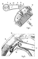
- the device 1 for torque support essentially comprises a strut 3, a support arm 2, and a connecting elastic bearing 4.
- the support arm 2 is with the interposition of a spherical bearing 11 with a bracket support bracket 5 a camshaft housing 6 and the strut 3 is a plate angle 7 with a Side member 8 of the vehicle body connected.
- a mounting block 9 is the Brace 3 supported on the strut tower 10 of the vehicle.
- the strut 3 and the support arm 2 of the torque arm 1 are approximately in one arranged horizontally and extend to support torque the unit and to absorb idling vibrations from the cylinder head cover 12 up to a side member 8 arranged on the side of the vehicle body, as shown in FIG. 2 shows closer.
- the strut 3 and the support arm 2 are together via an elastic bearing 4 connected, which is held in one eye of the support arm 2 and on one Bearing pin is supported, which is connected to the strut 3 and the support bracket 9 is.
- the strut 3 and the support bracket 9 can consist of a sheet profile instead also be made from a foot part.
- the bearing 4 in the support arm 2 has kidney-shaped recesses 13, 14 which in Direction of the pressure load and / or tensile load F2 of the support arm 2 are arranged one behind the other in a horizontal plane X - X.
- the recesses 13, 14 are the idle movements of the unit not transferred to the body or the side member 8. It results from the Recesses a strongly progressive characteristic of the bearing 4 in the pressure or Tensile loads.
- the free end of the support arm 2 facing away from the elastic bearing 4 is over a hard rubber bearing 11 or a ball joint connected to the console support bracket 5, which should only allow the rotational movement when the unit is springed.
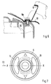
- the console support bracket 5 connected to the rubber bearing 11 is, as shown in FIG. 4, with its foot 15 on the camshaft housing 6, for example in recordings 16, 17 fixed and fixed by screws, which are shown only as lines.
- the strut 3 is on the one hand with the mounting bracket 9 and on the other hand over the Sheet metal bracket 7 rigid on the strut tower 10 or on the side member 8 of the body structure attached.
- the sheet metal bracket 7 has two supports 8 from above and from below overlapping legs 7a, 7b so that the strut 3 is a position to the carrier 8th occupies a force introduction from the strut 3 into the carrier 8 approximately in the middle Direction of arrow Z causes.
- connection of the mounting bracket 9 with the strut dome 10 takes place via a Parking 9a, which rests on the strut tower 10 and by means of a screw 20 is connected.
Landscapes
- Engineering & Computer Science (AREA)
- Chemical & Material Sciences (AREA)
- Combustion & Propulsion (AREA)
- Transportation (AREA)
- Mechanical Engineering (AREA)
- Vibration Prevention Devices (AREA)
- Arrangement Or Mounting Of Propulsion Units For Vehicles (AREA)
- Lubrication Of Internal Combustion Engines (AREA)
- Valve Device For Special Equipments (AREA)
Applications Claiming Priority (2)
| Application Number | Priority Date | Filing Date | Title |
|---|---|---|---|
| DE10024164 | 2000-05-17 | ||
| DE10024164A DE10024164B4 (de) | 2000-05-17 | 2000-05-17 | Vorrichtung zur Drehmomentabstützung einer Brennkraftmaschine |
Publications (3)
| Publication Number | Publication Date |
|---|---|
| EP1155893A2 true EP1155893A2 (fr) | 2001-11-21 |
| EP1155893A3 EP1155893A3 (fr) | 2003-07-02 |
| EP1155893B1 EP1155893B1 (fr) | 2005-07-13 |
Family
ID=7642390
Family Applications (1)
| Application Number | Title | Priority Date | Filing Date |
|---|---|---|---|
| EP01107993A Expired - Lifetime EP1155893B1 (fr) | 2000-05-17 | 2001-03-29 | Dispositif d'absorption de couple d'un moteur à combustion interne |
Country Status (6)
| Country | Link |
|---|---|
| US (2) | US6629576B2 (fr) |
| EP (1) | EP1155893B1 (fr) |
| JP (1) | JP3393864B2 (fr) |
| AT (1) | ATE299447T1 (fr) |
| DE (2) | DE10024164B4 (fr) |
| ES (1) | ES2241707T3 (fr) |
Families Citing this family (14)
| Publication number | Priority date | Publication date | Assignee | Title |
|---|---|---|---|---|
| FR2884181B1 (fr) * | 2005-04-11 | 2007-06-15 | Renault Sas | Ensemble de moteur d'un vehicule |
| FR2884210B1 (fr) * | 2005-04-12 | 2007-06-15 | Hutchinson Sa | Dispositif de suspension d'un moteur sur un chassis de bogie |
| DE102005055396A1 (de) | 2005-11-17 | 2007-05-24 | Automotive Group Ise Innomotive Systems Europe Gmbh | Drehmomentquerträger |
| DE102008039479A1 (de) | 2008-08-23 | 2010-02-25 | Dr. Ing. H.C. F. Porsche Aktiengesellschaft | Vorrichtung zur Lagerung einer Antriebseinheit in einem Kraftfahrzeug |
| US8215444B2 (en) * | 2009-07-09 | 2012-07-10 | Ford Global Technologies | Roll restrictor system for an automotive powertrain |
| GB201004473D0 (en) * | 2010-03-17 | 2010-05-05 | Trysome Ltd | Lightweight engine mounting |
| DE102011111236A1 (de) * | 2011-08-20 | 2013-02-21 | GM Global Technology Operations LLC (n. d. Gesetzen des Staates Delaware) | Kraftfahrzeugkarosserie |
| US8596403B2 (en) * | 2012-03-22 | 2013-12-03 | Toyota Motor Engineering & Manufacturing North America, Inc. | Motor mounting assemblies for electric vehicles and electric vehicles comprising the same |
| DE102013208231A1 (de) * | 2013-05-06 | 2014-11-06 | Mahle International Gmbh | Zylinderkopfhaube |
| US9158868B2 (en) * | 2013-08-22 | 2015-10-13 | GM Global Technology Operations LLC | Vehicle powertrain mounting system and method of designing same |
| US20150158372A1 (en) * | 2013-12-11 | 2015-06-11 | Eric F. DeHesselle | Torque strut |
| DE102013113964A1 (de) * | 2013-12-12 | 2015-06-18 | Dr. Ing. H.C. F. Porsche Aktiengesellschaft | Lageranordnung |
| JP6551200B2 (ja) * | 2015-12-02 | 2019-07-31 | スズキ株式会社 | 車両用内燃機関の支持装置 |
| DE102017209475A1 (de) * | 2017-06-06 | 2018-12-06 | Audi Ag | Aggregatlagerung für ein Kraftfahrzeug |
Citations (1)
| Publication number | Priority date | Publication date | Assignee | Title |
|---|---|---|---|---|
| DE4209613A1 (de) | 1991-04-04 | 1992-10-08 | Volkswagen Ag | Aggregatlagerung mit einer drehmomentenabstuetzung |
Family Cites Families (26)
| Publication number | Priority date | Publication date | Assignee | Title |
|---|---|---|---|---|
| SE334550B (fr) * | 1965-05-11 | 1971-04-26 | Saab Scania Ab | |
| JPS4819963B1 (fr) * | 1968-09-24 | 1973-06-18 | ||
| US3841426A (en) * | 1972-12-07 | 1974-10-15 | Fmc Corp | Engine isolation system |
| US3825090A (en) * | 1973-08-08 | 1974-07-23 | Gen Motors Corp | Rotary engine and transmission assembly mounting system |
| FR2265565B1 (fr) * | 1974-03-28 | 1977-06-17 | Peugeot & Renault | |
| US4240517A (en) * | 1979-04-13 | 1980-12-23 | General Motors Corporation | Powertrain and independent suspension mounting arrangement for front-wheel-drive vehicle |
| JPS56108307A (en) * | 1980-02-01 | 1981-08-27 | Nissan Motor Co Ltd | Device for supporting engine |
| JPS5863519A (ja) * | 1981-10-12 | 1983-04-15 | Nissan Motor Co Ltd | パワ−ユニツトのマウンテイング装置 |
| US4518058A (en) * | 1981-12-21 | 1985-05-21 | Moog Automotive, Inc. | Engine torgue resisting strut and vibration damper |
| DE3510335A1 (de) * | 1985-03-22 | 1986-10-16 | Adam Opel AG, 6090 Rüsselsheim | Kraftfahrzeug |
| US4685531A (en) * | 1986-03-31 | 1987-08-11 | General Motors Corporation | Motor vehicle power train torque strut |
| US5039073A (en) * | 1987-04-06 | 1991-08-13 | Cooper Tire & Rubber Company | Mount for controlling or isolating vibration |
| US4779834A (en) * | 1987-08-07 | 1988-10-25 | General Motors Corporation | Engine displacement limiter |
| SE466996B (sv) * | 1987-12-03 | 1992-05-11 | Volvo Ab | Anordning foer upphaengning av en motor i ett fordon |
| DE3808762A1 (de) * | 1988-03-16 | 1989-09-28 | Porsche Ag | Lagerung fuer eine motor-getriebeeinheit |
| JP2678313B2 (ja) * | 1989-05-31 | 1997-11-17 | スズキ株式会社 | エンジンマウント装置 |
| US5205374A (en) * | 1991-06-13 | 1993-04-27 | Dana Corporation | Synthetic engine mount strut |
| DE4209316A1 (de) | 1992-03-23 | 1993-09-30 | Krupp Industrietech | Verlegbare Brücke |
| US5570757A (en) * | 1993-11-22 | 1996-11-05 | Textron Inc. | Engine mounting system for a car |
| FR2731184B1 (fr) * | 1995-03-02 | 1997-06-27 | Peugeot | Dispositif de suspension d'un groupe moto-propulseur sur la structure d'un vehicule automobile |
| FR2736008B1 (fr) * | 1995-06-29 | 1997-08-22 | Peugeot | Module de suspension d'un groupe moto-propulseur sur la structure d'un vehicule automobile |
| DE19731128C2 (de) * | 1997-07-19 | 1999-09-23 | Volkswagen Ag | Pendelstütze für ein Aggregat in einem Kraftfahrzeug und elastisches Aggregatelager |
| JPH10114226A (ja) * | 1997-09-19 | 1998-05-06 | Suzuki Motor Corp | エンジンマウント装置 |
| DE19839521C1 (de) * | 1998-08-29 | 2000-03-09 | Daimler Chrysler Ag | Vorbaustruktur für ein Kraftfahrzeug |
| US6234268B1 (en) * | 2000-01-14 | 2001-05-22 | Daimlerchrysler Corporation | Torque strut with end weights |
| US6390223B1 (en) * | 2000-01-14 | 2002-05-21 | Daimlerchrysler Corporation | Engine/transmission combination mounting system |
-
2000
- 2000-05-17 DE DE10024164A patent/DE10024164B4/de not_active Expired - Fee Related
-
2001
- 2001-03-29 EP EP01107993A patent/EP1155893B1/fr not_active Expired - Lifetime
- 2001-03-29 AT AT01107993T patent/ATE299447T1/de not_active IP Right Cessation
- 2001-03-29 DE DE50106717T patent/DE50106717D1/de not_active Expired - Lifetime
- 2001-03-29 ES ES01107993T patent/ES2241707T3/es not_active Expired - Lifetime
- 2001-05-14 JP JP2001143605A patent/JP3393864B2/ja not_active Expired - Fee Related
- 2001-05-17 US US09/858,925 patent/US6629576B2/en not_active Expired - Fee Related
-
2003
- 2003-08-15 US US10/641,081 patent/US20040031638A1/en not_active Abandoned
Patent Citations (1)
| Publication number | Priority date | Publication date | Assignee | Title |
|---|---|---|---|---|
| DE4209613A1 (de) | 1991-04-04 | 1992-10-08 | Volkswagen Ag | Aggregatlagerung mit einer drehmomentenabstuetzung |
Also Published As
| Publication number | Publication date |
|---|---|
| US20040031638A1 (en) | 2004-02-19 |
| DE10024164A1 (de) | 2001-11-29 |
| ES2241707T3 (es) | 2005-11-01 |
| US20020011376A1 (en) | 2002-01-31 |
| ATE299447T1 (de) | 2005-07-15 |
| US6629576B2 (en) | 2003-10-07 |
| EP1155893A3 (fr) | 2003-07-02 |
| JP3393864B2 (ja) | 2003-04-07 |
| DE10024164B4 (de) | 2004-07-01 |
| EP1155893B1 (fr) | 2005-07-13 |
| DE50106717D1 (de) | 2005-08-18 |
| JP2001328440A (ja) | 2001-11-27 |
Similar Documents
| Publication | Publication Date | Title |
|---|---|---|
| EP2001733B1 (fr) | Motocyclette avec suspension de roue avant | |
| DE102008045492B4 (de) | Federdämpfungssystem mit mindestens zwei Gasfedern | |
| EP1076783B1 (fr) | Fixation pour un montant de suspension ou un amortisseur pneumatique d'une suspension de roue | |
| DE10024164B4 (de) | Vorrichtung zur Drehmomentabstützung einer Brennkraftmaschine | |
| EP1512560B1 (fr) | Chassis réglable | |
| DE2747561A1 (de) | Einzelradaufhaengung fuer kraftfahrzeuge | |
| DE102005029641A1 (de) | Radaufhängung | |
| DE102006058561A1 (de) | Funktionseinrichtung mit schwenkbarem Element | |
| DE102010023985A1 (de) | Radaufhängung | |
| DE3820676A1 (de) | Vorrichtung zum vermindern von karosserieschwingungen | |
| DE69919140T2 (de) | Befestigungsanordung einer antriebseinheit für fahrzeuge | |
| DE1555975A1 (de) | Lagerung fuer eine kippbare Fahrerkanbine von Motorfahrzeugen | |
| DE102007021228B4 (de) | Stossdämpfer - Schwenklagerverbindung einer Radaufhängung eines Kraftfahrzeugs | |
| DE102017220203A1 (de) | Aggregatelagerung für ein Antriebsaggregat in einem Fahrzeug | |
| DE19960457C2 (de) | Lagerung für ein Dämpferbein oder eine Luftfeder einer Radaufhängung | |
| DE102005034921A1 (de) | Federbeinbaugruppe mit umgedrehter Luftfederkonfiguration | |
| DE19753689B4 (de) | Aufhängungsvorrichtung für einen Vergaser eines Verbrennungsmotors | |
| DE19827864C1 (de) | Radaufhängung für ein Kraftfahrzeug | |
| DE102017211277A1 (de) | Radaufhängung für ein Kraftfahrzeug | |
| DE3741465A1 (de) | Stiftgelenkaufhaengung eines teleskopstossdaempfers oder eines federbeins fuer kraftfahrzeuge | |
| DE102018207616A1 (de) | Radaufhängung für ein Kraftfahrzeug | |
| DE10029881A1 (de) | Gabelstapler | |
| DE102009053125A1 (de) | Einrichtung zur aktiven Höhenverstellung einer Karosserie eines Fahrzeuges | |
| DE10037889C1 (de) | Kippvorrichtung für ein Fahrerhaus | |
| DE102016004703A1 (de) | Radaufhängung für ein Kraftfahrzeug |
Legal Events
| Date | Code | Title | Description |
|---|---|---|---|
| PUAI | Public reference made under article 153(3) epc to a published international application that has entered the european phase |
Free format text: ORIGINAL CODE: 0009012 |
|
| AK | Designated contracting states |
Kind code of ref document: A2 Designated state(s): AT BE CH CY DE DK ES FI FR GB GR IE IT LI LU MC NL PT SE TR |
|
| AX | Request for extension of the european patent |
Free format text: AL;LT;LV;MK;RO;SI |
|
| PUAL | Search report despatched |
Free format text: ORIGINAL CODE: 0009013 |
|
| AK | Designated contracting states |
Designated state(s): AT BE CH CY DE DK ES FI FR GB GR IE IT LI LU MC NL PT SE TR |
|
| AX | Request for extension of the european patent |
Extension state: AL LT LV MK RO SI |
|
| 17P | Request for examination filed |
Effective date: 20040102 |
|
| AKX | Designation fees paid |
Designated state(s): AT DE ES FR GB IT |
|
| 17Q | First examination report despatched |
Effective date: 20040830 |
|
| GRAP | Despatch of communication of intention to grant a patent |
Free format text: ORIGINAL CODE: EPIDOSNIGR1 |
|
| GRAS | Grant fee paid |
Free format text: ORIGINAL CODE: EPIDOSNIGR3 |
|
| GRAA | (expected) grant |
Free format text: ORIGINAL CODE: 0009210 |
|
| AK | Designated contracting states |
Kind code of ref document: B1 Designated state(s): AT DE ES FR GB IT |
|
| REG | Reference to a national code |
Ref country code: GB Ref legal event code: FG4D Free format text: NOT ENGLISH |
|
| REF | Corresponds to: |
Ref document number: 50106717 Country of ref document: DE Date of ref document: 20050818 Kind code of ref document: P |
|
| REG | Reference to a national code |
Ref country code: ES Ref legal event code: FG2A Ref document number: 2241707 Country of ref document: ES Kind code of ref document: T3 |
|
| GBT | Gb: translation of ep patent filed (gb section 77(6)(a)/1977) | ||
| ET | Fr: translation filed | ||
| PLBE | No opposition filed within time limit |
Free format text: ORIGINAL CODE: 0009261 |
|
| STAA | Information on the status of an ep patent application or granted ep patent |
Free format text: STATUS: NO OPPOSITION FILED WITHIN TIME LIMIT |
|
| 26N | No opposition filed |
Effective date: 20060418 |
|
| PGFP | Annual fee paid to national office [announced via postgrant information from national office to epo] |
Ref country code: ES Payment date: 20080328 Year of fee payment: 8 |
|
| PGFP | Annual fee paid to national office [announced via postgrant information from national office to epo] |
Ref country code: GB Payment date: 20080320 Year of fee payment: 8 |
|
| PGFP | Annual fee paid to national office [announced via postgrant information from national office to epo] |
Ref country code: AT Payment date: 20080314 Year of fee payment: 8 |
|
| REG | Reference to a national code |
Ref country code: ES Ref legal event code: PC2A |
|
| REG | Reference to a national code |
Ref country code: FR Ref legal event code: TP |
|
| PG25 | Lapsed in a contracting state [announced via postgrant information from national office to epo] |
Ref country code: AT Free format text: LAPSE BECAUSE OF NON-PAYMENT OF DUE FEES Effective date: 20090329 |
|
| GBPC | Gb: european patent ceased through non-payment of renewal fee |
Effective date: 20090329 |
|
| REG | Reference to a national code |
Ref country code: FR Ref legal event code: CD |
|
| PG25 | Lapsed in a contracting state [announced via postgrant information from national office to epo] |
Ref country code: GB Free format text: LAPSE BECAUSE OF NON-PAYMENT OF DUE FEES Effective date: 20090329 |
|
| REG | Reference to a national code |
Ref country code: ES Ref legal event code: FD2A Effective date: 20090330 |
|
| PG25 | Lapsed in a contracting state [announced via postgrant information from national office to epo] |
Ref country code: ES Free format text: LAPSE BECAUSE OF NON-PAYMENT OF DUE FEES Effective date: 20090330 |
|
| PGFP | Annual fee paid to national office [announced via postgrant information from national office to epo] |
Ref country code: IT Payment date: 20100327 Year of fee payment: 10 |
|
| REG | Reference to a national code |
Ref country code: FR Ref legal event code: TP |
|
| PGFP | Annual fee paid to national office [announced via postgrant information from national office to epo] |
Ref country code: FR Payment date: 20110404 Year of fee payment: 11 |
|
| PG25 | Lapsed in a contracting state [announced via postgrant information from national office to epo] |
Ref country code: IT Free format text: LAPSE BECAUSE OF NON-PAYMENT OF DUE FEES Effective date: 20110329 |
|
| REG | Reference to a national code |
Ref country code: FR Ref legal event code: ST Effective date: 20121130 |
|
| PG25 | Lapsed in a contracting state [announced via postgrant information from national office to epo] |
Ref country code: FR Free format text: LAPSE BECAUSE OF NON-PAYMENT OF DUE FEES Effective date: 20120402 |
|
| PGFP | Annual fee paid to national office [announced via postgrant information from national office to epo] |
Ref country code: DE Payment date: 20180403 Year of fee payment: 18 |
|
| REG | Reference to a national code |
Ref country code: DE Ref legal event code: R119 Ref document number: 50106717 Country of ref document: DE |
|
| PG25 | Lapsed in a contracting state [announced via postgrant information from national office to epo] |
Ref country code: DE Free format text: LAPSE BECAUSE OF NON-PAYMENT OF DUE FEES Effective date: 20191001 |