EP1155893B1 - Dispositif d'absorption de couple d'un moteur à combustion interne - Google Patents
Dispositif d'absorption de couple d'un moteur à combustion interne Download PDFInfo
- Publication number
- EP1155893B1 EP1155893B1 EP01107993A EP01107993A EP1155893B1 EP 1155893 B1 EP1155893 B1 EP 1155893B1 EP 01107993 A EP01107993 A EP 01107993A EP 01107993 A EP01107993 A EP 01107993A EP 1155893 B1 EP1155893 B1 EP 1155893B1
- Authority
- EP
- European Patent Office
- Prior art keywords
- strut
- bearing
- support
- support arm
- vehicle
- Prior art date
- Legal status (The legal status is an assumption and is not a legal conclusion. Google has not performed a legal analysis and makes no representation as to the accuracy of the status listed.)
- Expired - Lifetime
Links
Images


Classifications
-
- B—PERFORMING OPERATIONS; TRANSPORTING
- B60—VEHICLES IN GENERAL
- B60K—ARRANGEMENT OR MOUNTING OF PROPULSION UNITS OR OF TRANSMISSIONS IN VEHICLES; ARRANGEMENT OR MOUNTING OF PLURAL DIVERSE PRIME-MOVERS IN VEHICLES; AUXILIARY DRIVES FOR VEHICLES; INSTRUMENTATION OR DASHBOARDS FOR VEHICLES; ARRANGEMENTS IN CONNECTION WITH COOLING, AIR INTAKE, GAS EXHAUST OR FUEL SUPPLY OF PROPULSION UNITS IN VEHICLES
- B60K5/00—Arrangement or mounting of internal-combustion or jet-propulsion units
- B60K5/12—Arrangement of engine supports
- B60K5/1241—Link-type support
-
- B—PERFORMING OPERATIONS; TRANSPORTING
- B60—VEHICLES IN GENERAL
- B60K—ARRANGEMENT OR MOUNTING OF PROPULSION UNITS OR OF TRANSMISSIONS IN VEHICLES; ARRANGEMENT OR MOUNTING OF PLURAL DIVERSE PRIME-MOVERS IN VEHICLES; AUXILIARY DRIVES FOR VEHICLES; INSTRUMENTATION OR DASHBOARDS FOR VEHICLES; ARRANGEMENTS IN CONNECTION WITH COOLING, AIR INTAKE, GAS EXHAUST OR FUEL SUPPLY OF PROPULSION UNITS IN VEHICLES
- B60K5/00—Arrangement or mounting of internal-combustion or jet-propulsion units
- B60K5/12—Arrangement of engine supports
- B60K5/1208—Resilient supports
- B60K5/1216—Resilient supports characterised by the location of the supports relative to the motor or to each other
Definitions
- the invention relates to a device for torque support of a Internal combustion engine according to the preamble of claim 1.
- From DE 42 09 613 A1 is a unit bearing with a torque support consisting of a rigid support known. This prop is between an aggregate and a vehicle frame, wherein in the support elastic bearings are provided.
- the one Support arm comprises, on the one hand via an elastic bearing with the Internal combustion engine and further with its other end via a bearing with a carrier of the vehicle body is connected.
- For vertical support of the Stützenarmes is another strut provided, on the one hand at the connection point between the support arm to the carrier and on the other hand with his turned away free end connected to a vehicle structure.
- the object of the invention is to provide a device for torque support of a Internal combustion engine by means of a torque arm to create, on the one hand Idle movements of the unit allows and not forwarding and on the other hand a Torque support during operation ensures and beyond a simple Assuring installation.
- the advantages achieved by the invention consist essentially in that the Internal combustion engine at moments occurring during operation via the torque arm is supported on the longitudinal member of the vehicle body. Also according to the invention On each side of the unit to the longitudinal members facing torque arms be arranged.
- the torque arm is formed at least in two parts and consists of one with a Zykinderkopfhaube and / or a camshaft housing under Interposition of a relatively stiff joint bearing connected support arm, as well a subsequent and held on a stationary elastic bearing strut, the is attached end to a support of the body structure.
- the Support arm with one end on the cylinder head cover or on the camshaft housing fastened by a console in which the joint bearing is held, and with his other Towandten end supported in the elastic bearing, which has a Receptacle is stored stationary on Federbeindom.
- Training and support of the torque arm will be the power coming from the unit is generated, linearly introduced into the side members of the body, where vibrations be kept away from the body during idling of the engine.
- the strut is rigidly connected to the receiving block and rests with an end directed towards the support arm in the elastic bearing from being held in the receptacle.
- the cost of attaching the receptacle to the body structure low can be held, an existing screw point of a bearing block, in which the shock absorber is stored, also used.
- the strut is connected to the support arm via an elastic bearing, which in the Receiving bracket is held, wherein in one eye of the support arm, the elastic Bearing is arranged and this is located between the receiving block and the strut.
- the Receptacle overreaches the strut for attachment by means of two arms and to Attachment to the strut tower has this a shutdown, which on Federbeindom about at least one screw is fixed.
- the strut of the connection to the side member to the receiving block is rigid executed and the subsequent Stauerarm -ist on the elastic bearing as well pivotable about the pivot bearing, which is in one with the camshaft housing connected console support bracket, which is designed for this purpose with a foot, the can be fastened on the camshaft housing.
- the connecting elastic bearing between the strut and the support arm acts as So-called damping bearing and has a strong progressive tuned characteristic and comprises two kidney-shaped recesses, which in the direction of the pressure load of Torque arm are aligned one behind the other in a horizontal plane.
- the joint bearing of the support only rotational movements in the springs of the Allow aggregate. It can either be made of a rubber bearing with high radial Stiffness and relatively low torsional stiffness exist or as a ball joint be executed.
- the force generated by the unit linearly introduced into the body longitudinal beams can be, the connection of the support arm takes place on this carrier via a Sheet metal angle, which is connectable to the carrier of the body structure and this the carrier has from above and from below cross leg and the strut about the center of the Carrier ends.
- the sheet metal bracket is an easy-to-produce Blechfaltteil, which the power as possible centered in the side member via the walls lying in the direction of force initiates.
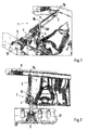
- the torque-assisting device 1 comprises a strut 3, a support arm 2, and a connecting elastic bearing 4.
- the support arm 2 is under Interposition of a spherical bearing 11 via a console support bracket 5 with a Camshaft housing 6 and the strut 3 is a sheet metal angle 7 with a Side member 8 of the vehicle body connected.
- a receiving block 9 is the Strut 3 supported on the strut tower 10 of the vehicle.
- the strut 3 and the support arm 2 of the torque arm 1 are approximately in one arranged horizontal plane and extend to the support of torques the unit and for receiving idle vibrations of the cylinder head cover 12 to a side of the vehicle body arranged side rail 8, as shown in FIG. 2 shows closer.
- the strut 3 and the support arm 2 are connected via an elastic bearing 4 with each other connected, which is held in one eye of the support arm 2 and on one Bearing pin is supported, which is connected to the strut 3 and the receiving block 9 is.
- the strut 3 and the receiving block 9 may instead consist of a sheet metal profile also be made of a footboard.
- the bearing 4 in the support arm 2 has kidney-shaped recesses 13, 14, which in Direction of the pressure load and / or tensile load F2 of the support arm 2 lying one behind the other in a horizontal plane X - X are arranged.
- the recesses 13, 14 are the idle movements of the unit not transferred to the body or the side member 8. It results from the Recesses a strong progressive characteristic of the bearing 4 in the printing or Tensile loads.
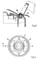
- the the elastic bearing 4 facing away from the free end of the support arm 2 is a hard rubber bearing 11 or a ball joint connected to the Konsolenstützbock 5, which should only allow the rotational movement when springs of the unit.
- the console support bracket 5 connected to the rubber mount 11 is, as FIG. 4 shows in more detail, with his foot 15 on the camshaft housing 6, for example in receptacles 16, 17th fixed and fixed by screws, which are shown only as lines.
- the strut 3 is on the one hand with the receiving block 9 and on the other hand over the Sheet metal bracket 7 rigidly on the strut tower 10 or on the longitudinal member 8 of the body structure attached.
- the sheet metal angle 7 two the carrier 8 from above and from below cross-leg 7a, 7b, so that the strut 3 a position to the carrier. 8 occupies which a force from the strut 3 in the carrier 8 approximately centrally in Arrow direction Z causes.
Landscapes
- Engineering & Computer Science (AREA)
- Chemical & Material Sciences (AREA)
- Combustion & Propulsion (AREA)
- Transportation (AREA)
- Mechanical Engineering (AREA)
- Vibration Prevention Devices (AREA)
- Arrangement Or Mounting Of Propulsion Units For Vehicles (AREA)
- Valve Device For Special Equipments (AREA)
- Lubrication Of Internal Combustion Engines (AREA)
Claims (7)
- Dispositif pour supporter le couple de rotation d'un moteur à combustion interne dans un véhicule, par l'intermédiaire d'au moins un appui de couple de rotation (1) qui est disposé dans le véhicule entre le moteur à combustion interne et une poutre (8) de la carrosserie du véhicule et est relié à la structure de la carrosserie, l'appui (1) du couple de rotation étant constitué en deux parties, d'un bras d'appui (2) et d'une entretoise (3) qui sont reliés entre eux par un palier (4), caractérisé en ce que l'appui du couple de rotation est disposé transversalement dans le véhicule, et le bras d'appui (2) est relié d'une part, par un palier d'articulation (11) rigide avec un axe de pivotement, à un capot de culasse (12), et/ou à un carter d'arbre à cames (6) et d'autre part, par un palier élastique (4) fixe avec un autre axe de pivotement, à l'entretoise (3), laquelle est fixée côté extrémité sur la poutre (8) de la structure de la carrosserie du véhicule.
- Dispositif selon la revendication 1, caractérisé en ce que le bras d'appui (2) est maintenu par une extrémité sur le capot de culasse (12) et/ou sur le carter d'arbre à cames (6) par une console de support (5), dans le palier d'articulation (11), et est soutenu, par son autre extrémité opposée, dans le palier élastique (4) lequel est monté en un emplacement fixe par un support de réception (9) sur le dôme (10) d'une jambe de force à ressort.
- Dispositif selon la revendication 2, caractérisé en ce que l'entretoise (3) est reliée rigidement au support de réception (9) et prend appui, par une extrémité dirigée vers le bras d'appui (2), dans le palier élastique (4) qui est maintenu dans le support de réception (9).
- Dispositif selon les revendications 2 ou 3, caractérisé en ce que le palier élastique (4) est disposé dans un oeillet d'appui du bras d'appui (2), et ce bras (2) se situe entre le support de réception (9) et l'entretoise (3) et le support de réception (9) passe sur l'entretoise (3) pour la fixation au moyen de deux bras (9c, 9d), et présente un gradin (9a) pour la fixation avec le dôme (10) de la jambe de force à ressort.
- Dispositif selon l'une des revendications 2 à 4, caractérisé en ce que la console d'appui (5) peut être fixée par son pied (16) dans des logements (16, 17) du carter d'arbre à cames (6).
- Dispositif selon une ou plusieurs des revendications précédentes, caractérisé en ce que le palier élastique (4), reliant le bras d'appui (2) à l'entretoise (3), est conçu comme palier d'amortissement avec deux évidements (13, 14) en forme de haricot qui sont orientés l'un derrière l'autre dans un plan horizontal (X-X), dans la direction de l'action (F2) de la pression sur l'appui (1) du couple de rotation.
- Dispositif selon une ou plusieurs des revendications précédentes, caractérisé en ce que l'entretoise (3) présente côté extrémité une équerre en tôle (7) qui est reliée à la poutre (8) de la structure de la carrosserie et comporte deux branches (7a, 7b) passant sur la poutre (8) depuis le haut et depuis le bas, et l'entretoise (3) se termine devant une âme de la poutre (8) de manière que l'introduction des forces (Z) s'effectue à peu près au milieu dans le profilé de la poutre.
Applications Claiming Priority (2)
| Application Number | Priority Date | Filing Date | Title |
|---|---|---|---|
| DE10024164 | 2000-05-17 | ||
| DE10024164A DE10024164B4 (de) | 2000-05-17 | 2000-05-17 | Vorrichtung zur Drehmomentabstützung einer Brennkraftmaschine |
Publications (3)
| Publication Number | Publication Date |
|---|---|
| EP1155893A2 EP1155893A2 (fr) | 2001-11-21 |
| EP1155893A3 EP1155893A3 (fr) | 2003-07-02 |
| EP1155893B1 true EP1155893B1 (fr) | 2005-07-13 |
Family
ID=7642390
Family Applications (1)
| Application Number | Title | Priority Date | Filing Date |
|---|---|---|---|
| EP01107993A Expired - Lifetime EP1155893B1 (fr) | 2000-05-17 | 2001-03-29 | Dispositif d'absorption de couple d'un moteur à combustion interne |
Country Status (6)
| Country | Link |
|---|---|
| US (2) | US6629576B2 (fr) |
| EP (1) | EP1155893B1 (fr) |
| JP (1) | JP3393864B2 (fr) |
| AT (1) | ATE299447T1 (fr) |
| DE (2) | DE10024164B4 (fr) |
| ES (1) | ES2241707T3 (fr) |
Families Citing this family (14)
| Publication number | Priority date | Publication date | Assignee | Title |
|---|---|---|---|---|
| FR2884181B1 (fr) * | 2005-04-11 | 2007-06-15 | Renault Sas | Ensemble de moteur d'un vehicule |
| FR2884210B1 (fr) * | 2005-04-12 | 2007-06-15 | Hutchinson Sa | Dispositif de suspension d'un moteur sur un chassis de bogie |
| DE102005055396A1 (de) | 2005-11-17 | 2007-05-24 | Automotive Group Ise Innomotive Systems Europe Gmbh | Drehmomentquerträger |
| DE102008039479A1 (de) | 2008-08-23 | 2010-02-25 | Dr. Ing. H.C. F. Porsche Aktiengesellschaft | Vorrichtung zur Lagerung einer Antriebseinheit in einem Kraftfahrzeug |
| US8215444B2 (en) * | 2009-07-09 | 2012-07-10 | Ford Global Technologies | Roll restrictor system for an automotive powertrain |
| GB201004473D0 (en) * | 2010-03-17 | 2010-05-05 | Trysome Ltd | Lightweight engine mounting |
| DE102011111236A1 (de) * | 2011-08-20 | 2013-02-21 | GM Global Technology Operations LLC (n. d. Gesetzen des Staates Delaware) | Kraftfahrzeugkarosserie |
| US8596403B2 (en) * | 2012-03-22 | 2013-12-03 | Toyota Motor Engineering & Manufacturing North America, Inc. | Motor mounting assemblies for electric vehicles and electric vehicles comprising the same |
| DE102013208231A1 (de) * | 2013-05-06 | 2014-11-06 | Mahle International Gmbh | Zylinderkopfhaube |
| US9158868B2 (en) * | 2013-08-22 | 2015-10-13 | GM Global Technology Operations LLC | Vehicle powertrain mounting system and method of designing same |
| US20150158372A1 (en) * | 2013-12-11 | 2015-06-11 | Eric F. DeHesselle | Torque strut |
| DE102013113964A1 (de) * | 2013-12-12 | 2015-06-18 | Dr. Ing. H.C. F. Porsche Aktiengesellschaft | Lageranordnung |
| JP6551200B2 (ja) * | 2015-12-02 | 2019-07-31 | スズキ株式会社 | 車両用内燃機関の支持装置 |
| DE102017209475A1 (de) * | 2017-06-06 | 2018-12-06 | Audi Ag | Aggregatlagerung für ein Kraftfahrzeug |
Family Cites Families (27)
| Publication number | Priority date | Publication date | Assignee | Title |
|---|---|---|---|---|
| SE334550B (fr) * | 1965-05-11 | 1971-04-26 | Saab Scania Ab | |
| JPS4819963B1 (fr) * | 1968-09-24 | 1973-06-18 | ||
| US3841426A (en) * | 1972-12-07 | 1974-10-15 | Fmc Corp | Engine isolation system |
| US3825090A (en) * | 1973-08-08 | 1974-07-23 | Gen Motors Corp | Rotary engine and transmission assembly mounting system |
| FR2265565B1 (fr) * | 1974-03-28 | 1977-06-17 | Peugeot & Renault | |
| US4240517A (en) * | 1979-04-13 | 1980-12-23 | General Motors Corporation | Powertrain and independent suspension mounting arrangement for front-wheel-drive vehicle |
| JPS56108307A (en) * | 1980-02-01 | 1981-08-27 | Nissan Motor Co Ltd | Device for supporting engine |
| JPS5863519A (ja) * | 1981-10-12 | 1983-04-15 | Nissan Motor Co Ltd | パワ−ユニツトのマウンテイング装置 |
| US4518058A (en) * | 1981-12-21 | 1985-05-21 | Moog Automotive, Inc. | Engine torgue resisting strut and vibration damper |
| DE3510335A1 (de) * | 1985-03-22 | 1986-10-16 | Adam Opel AG, 6090 Rüsselsheim | Kraftfahrzeug |
| US4685531A (en) * | 1986-03-31 | 1987-08-11 | General Motors Corporation | Motor vehicle power train torque strut |
| US5039073A (en) * | 1987-04-06 | 1991-08-13 | Cooper Tire & Rubber Company | Mount for controlling or isolating vibration |
| US4779834A (en) * | 1987-08-07 | 1988-10-25 | General Motors Corporation | Engine displacement limiter |
| SE466996B (sv) * | 1987-12-03 | 1992-05-11 | Volvo Ab | Anordning foer upphaengning av en motor i ett fordon |
| DE3808762A1 (de) * | 1988-03-16 | 1989-09-28 | Porsche Ag | Lagerung fuer eine motor-getriebeeinheit |
| JP2678313B2 (ja) * | 1989-05-31 | 1997-11-17 | スズキ株式会社 | エンジンマウント装置 |
| DE4209613A1 (de) * | 1991-04-04 | 1992-10-08 | Volkswagen Ag | Aggregatlagerung mit einer drehmomentenabstuetzung |
| US5205374A (en) * | 1991-06-13 | 1993-04-27 | Dana Corporation | Synthetic engine mount strut |
| DE4209316A1 (de) | 1992-03-23 | 1993-09-30 | Krupp Industrietech | Verlegbare Brücke |
| US5570757A (en) * | 1993-11-22 | 1996-11-05 | Textron Inc. | Engine mounting system for a car |
| FR2731184B1 (fr) * | 1995-03-02 | 1997-06-27 | Peugeot | Dispositif de suspension d'un groupe moto-propulseur sur la structure d'un vehicule automobile |
| FR2736008B1 (fr) * | 1995-06-29 | 1997-08-22 | Peugeot | Module de suspension d'un groupe moto-propulseur sur la structure d'un vehicule automobile |
| DE19731128C2 (de) * | 1997-07-19 | 1999-09-23 | Volkswagen Ag | Pendelstütze für ein Aggregat in einem Kraftfahrzeug und elastisches Aggregatelager |
| JPH10114226A (ja) * | 1997-09-19 | 1998-05-06 | Suzuki Motor Corp | エンジンマウント装置 |
| DE19839521C1 (de) * | 1998-08-29 | 2000-03-09 | Daimler Chrysler Ag | Vorbaustruktur für ein Kraftfahrzeug |
| US6234268B1 (en) * | 2000-01-14 | 2001-05-22 | Daimlerchrysler Corporation | Torque strut with end weights |
| US6390223B1 (en) * | 2000-01-14 | 2002-05-21 | Daimlerchrysler Corporation | Engine/transmission combination mounting system |
-
2000
- 2000-05-17 DE DE10024164A patent/DE10024164B4/de not_active Expired - Fee Related
-
2001
- 2001-03-29 ES ES01107993T patent/ES2241707T3/es not_active Expired - Lifetime
- 2001-03-29 AT AT01107993T patent/ATE299447T1/de not_active IP Right Cessation
- 2001-03-29 EP EP01107993A patent/EP1155893B1/fr not_active Expired - Lifetime
- 2001-03-29 DE DE50106717T patent/DE50106717D1/de not_active Expired - Lifetime
- 2001-05-14 JP JP2001143605A patent/JP3393864B2/ja not_active Expired - Fee Related
- 2001-05-17 US US09/858,925 patent/US6629576B2/en not_active Expired - Fee Related
-
2003
- 2003-08-15 US US10/641,081 patent/US20040031638A1/en not_active Abandoned
Also Published As
| Publication number | Publication date |
|---|---|
| JP3393864B2 (ja) | 2003-04-07 |
| DE10024164A1 (de) | 2001-11-29 |
| ES2241707T3 (es) | 2005-11-01 |
| DE10024164B4 (de) | 2004-07-01 |
| US20040031638A1 (en) | 2004-02-19 |
| EP1155893A2 (fr) | 2001-11-21 |
| JP2001328440A (ja) | 2001-11-27 |
| US6629576B2 (en) | 2003-10-07 |
| ATE299447T1 (de) | 2005-07-15 |
| EP1155893A3 (fr) | 2003-07-02 |
| US20020011376A1 (en) | 2002-01-31 |
| DE50106717D1 (de) | 2005-08-18 |
Similar Documents
| Publication | Publication Date | Title |
|---|---|---|
| EP1155893B1 (fr) | Dispositif d'absorption de couple d'un moteur à combustion interne | |
| EP1076783B1 (fr) | Fixation pour un montant de suspension ou un amortisseur pneumatique d'une suspension de roue | |
| DE1455649A1 (de) | Aufhaengung fuer Kraftfahrzeuge | |
| EP1512560B1 (fr) | Chassis réglable | |
| EP1970293B1 (fr) | Véhicule | |
| EP2199121B1 (fr) | Suspension de roue pour véhicules automobiles | |
| DE69919140T2 (de) | Befestigungsanordung einer antriebseinheit für fahrzeuge | |
| DE3939192C2 (de) | Gelenkverbindung zwischen dem kippzylinder und dem kippbaren fahrerhaus eines lastkraftwagens | |
| DE1555975A1 (de) | Lagerung fuer eine kippbare Fahrerkanbine von Motorfahrzeugen | |
| EP0265675B1 (fr) | Unité de montage comportant un cadre auxiliaire sur lequel sont montés de façon pivotante les bras de suspension | |
| EP1293404B1 (fr) | Bras d'essuie-glace et dispositif d'essuie-glace, en particulier pour un véhicule | |
| DE102017220203A1 (de) | Aggregatelagerung für ein Antriebsaggregat in einem Fahrzeug | |
| DE19960457C2 (de) | Lagerung für ein Dämpferbein oder eine Luftfeder einer Radaufhängung | |
| DE19827864C1 (de) | Radaufhängung für ein Kraftfahrzeug | |
| DE102017211277A1 (de) | Radaufhängung für ein Kraftfahrzeug | |
| DE10029881B4 (de) | Gabelstapler | |
| DE69713696T2 (de) | Aufhängungsvorrichtung, insbesondere für Kraftfahrzeuge | |
| DE19748778B4 (de) | Lagervorrichtung für einen Triebsatzprüfstand | |
| EP1206365B1 (fr) | Palier pour unite d'entrainement | |
| DE102018207616A1 (de) | Radaufhängung für ein Kraftfahrzeug | |
| DE102016004703A1 (de) | Radaufhängung für ein Kraftfahrzeug | |
| DE2722926A1 (de) | Elastische kuehlerlagerung | |
| DE3217171A1 (de) | Schwingungsgedaempfte aufhaengung fuer ein antriebsaggregat eines fahrzeuges in einer aufbaustruktur | |
| DE19610690C2 (de) | Radaufhängung für ein Kraftfahrzeug | |
| DE3809996A1 (de) | Hintere aufhaengungseinrichtung fuer motorfahrzeuge |
Legal Events
| Date | Code | Title | Description |
|---|---|---|---|
| PUAI | Public reference made under article 153(3) epc to a published international application that has entered the european phase |
Free format text: ORIGINAL CODE: 0009012 |
|
| AK | Designated contracting states |
Kind code of ref document: A2 Designated state(s): AT BE CH CY DE DK ES FI FR GB GR IE IT LI LU MC NL PT SE TR |
|
| AX | Request for extension of the european patent |
Free format text: AL;LT;LV;MK;RO;SI |
|
| PUAL | Search report despatched |
Free format text: ORIGINAL CODE: 0009013 |
|
| AK | Designated contracting states |
Designated state(s): AT BE CH CY DE DK ES FI FR GB GR IE IT LI LU MC NL PT SE TR |
|
| AX | Request for extension of the european patent |
Extension state: AL LT LV MK RO SI |
|
| 17P | Request for examination filed |
Effective date: 20040102 |
|
| AKX | Designation fees paid |
Designated state(s): AT DE ES FR GB IT |
|
| 17Q | First examination report despatched |
Effective date: 20040830 |
|
| GRAP | Despatch of communication of intention to grant a patent |
Free format text: ORIGINAL CODE: EPIDOSNIGR1 |
|
| GRAS | Grant fee paid |
Free format text: ORIGINAL CODE: EPIDOSNIGR3 |
|
| GRAA | (expected) grant |
Free format text: ORIGINAL CODE: 0009210 |
|
| AK | Designated contracting states |
Kind code of ref document: B1 Designated state(s): AT DE ES FR GB IT |
|
| REG | Reference to a national code |
Ref country code: GB Ref legal event code: FG4D Free format text: NOT ENGLISH |
|
| REF | Corresponds to: |
Ref document number: 50106717 Country of ref document: DE Date of ref document: 20050818 Kind code of ref document: P |
|
| REG | Reference to a national code |
Ref country code: ES Ref legal event code: FG2A Ref document number: 2241707 Country of ref document: ES Kind code of ref document: T3 |
|
| GBT | Gb: translation of ep patent filed (gb section 77(6)(a)/1977) | ||
| ET | Fr: translation filed | ||
| PLBE | No opposition filed within time limit |
Free format text: ORIGINAL CODE: 0009261 |
|
| STAA | Information on the status of an ep patent application or granted ep patent |
Free format text: STATUS: NO OPPOSITION FILED WITHIN TIME LIMIT |
|
| 26N | No opposition filed |
Effective date: 20060418 |
|
| PGFP | Annual fee paid to national office [announced via postgrant information from national office to epo] |
Ref country code: ES Payment date: 20080328 Year of fee payment: 8 |
|
| PGFP | Annual fee paid to national office [announced via postgrant information from national office to epo] |
Ref country code: GB Payment date: 20080320 Year of fee payment: 8 |
|
| PGFP | Annual fee paid to national office [announced via postgrant information from national office to epo] |
Ref country code: AT Payment date: 20080314 Year of fee payment: 8 |
|
| REG | Reference to a national code |
Ref country code: ES Ref legal event code: PC2A |
|
| REG | Reference to a national code |
Ref country code: FR Ref legal event code: TP |
|
| PG25 | Lapsed in a contracting state [announced via postgrant information from national office to epo] |
Ref country code: AT Free format text: LAPSE BECAUSE OF NON-PAYMENT OF DUE FEES Effective date: 20090329 |
|
| GBPC | Gb: european patent ceased through non-payment of renewal fee |
Effective date: 20090329 |
|
| REG | Reference to a national code |
Ref country code: FR Ref legal event code: CD |
|
| PG25 | Lapsed in a contracting state [announced via postgrant information from national office to epo] |
Ref country code: GB Free format text: LAPSE BECAUSE OF NON-PAYMENT OF DUE FEES Effective date: 20090329 |
|
| REG | Reference to a national code |
Ref country code: ES Ref legal event code: FD2A Effective date: 20090330 |
|
| PG25 | Lapsed in a contracting state [announced via postgrant information from national office to epo] |
Ref country code: ES Free format text: LAPSE BECAUSE OF NON-PAYMENT OF DUE FEES Effective date: 20090330 |
|
| PGFP | Annual fee paid to national office [announced via postgrant information from national office to epo] |
Ref country code: IT Payment date: 20100327 Year of fee payment: 10 |
|
| REG | Reference to a national code |
Ref country code: FR Ref legal event code: TP |
|
| PGFP | Annual fee paid to national office [announced via postgrant information from national office to epo] |
Ref country code: FR Payment date: 20110404 Year of fee payment: 11 |
|
| PG25 | Lapsed in a contracting state [announced via postgrant information from national office to epo] |
Ref country code: IT Free format text: LAPSE BECAUSE OF NON-PAYMENT OF DUE FEES Effective date: 20110329 |
|
| REG | Reference to a national code |
Ref country code: FR Ref legal event code: ST Effective date: 20121130 |
|
| PG25 | Lapsed in a contracting state [announced via postgrant information from national office to epo] |
Ref country code: FR Free format text: LAPSE BECAUSE OF NON-PAYMENT OF DUE FEES Effective date: 20120402 |
|
| PGFP | Annual fee paid to national office [announced via postgrant information from national office to epo] |
Ref country code: DE Payment date: 20180403 Year of fee payment: 18 |
|
| REG | Reference to a national code |
Ref country code: DE Ref legal event code: R119 Ref document number: 50106717 Country of ref document: DE |
|
| PG25 | Lapsed in a contracting state [announced via postgrant information from national office to epo] |
Ref country code: DE Free format text: LAPSE BECAUSE OF NON-PAYMENT OF DUE FEES Effective date: 20191001 |