EP1155893B1 - Apparatus for supporting the torque load of an internal combustion engine - Google Patents
Apparatus for supporting the torque load of an internal combustion engine Download PDFInfo
- Publication number
- EP1155893B1 EP1155893B1 EP01107993A EP01107993A EP1155893B1 EP 1155893 B1 EP1155893 B1 EP 1155893B1 EP 01107993 A EP01107993 A EP 01107993A EP 01107993 A EP01107993 A EP 01107993A EP 1155893 B1 EP1155893 B1 EP 1155893B1
- Authority
- EP
- European Patent Office
- Prior art keywords
- strut
- bearing
- support
- support arm
- vehicle
- Prior art date
- Legal status (The legal status is an assumption and is not a legal conclusion. Google has not performed a legal analysis and makes no representation as to the accuracy of the status listed.)
- Expired - Lifetime
Links
Images


Classifications
-
- B—PERFORMING OPERATIONS; TRANSPORTING
- B60—VEHICLES IN GENERAL
- B60K—ARRANGEMENT OR MOUNTING OF PROPULSION UNITS OR OF TRANSMISSIONS IN VEHICLES; ARRANGEMENT OR MOUNTING OF PLURAL DIVERSE PRIME-MOVERS IN VEHICLES; AUXILIARY DRIVES FOR VEHICLES; INSTRUMENTATION OR DASHBOARDS FOR VEHICLES; ARRANGEMENTS IN CONNECTION WITH COOLING, AIR INTAKE, GAS EXHAUST OR FUEL SUPPLY OF PROPULSION UNITS IN VEHICLES
- B60K5/00—Arrangement or mounting of internal-combustion or jet-propulsion units
- B60K5/12—Arrangement of engine supports
- B60K5/1241—Link-type support
-
- B—PERFORMING OPERATIONS; TRANSPORTING
- B60—VEHICLES IN GENERAL
- B60K—ARRANGEMENT OR MOUNTING OF PROPULSION UNITS OR OF TRANSMISSIONS IN VEHICLES; ARRANGEMENT OR MOUNTING OF PLURAL DIVERSE PRIME-MOVERS IN VEHICLES; AUXILIARY DRIVES FOR VEHICLES; INSTRUMENTATION OR DASHBOARDS FOR VEHICLES; ARRANGEMENTS IN CONNECTION WITH COOLING, AIR INTAKE, GAS EXHAUST OR FUEL SUPPLY OF PROPULSION UNITS IN VEHICLES
- B60K5/00—Arrangement or mounting of internal-combustion or jet-propulsion units
- B60K5/12—Arrangement of engine supports
- B60K5/1208—Resilient supports
- B60K5/1216—Resilient supports characterised by the location of the supports relative to the motor or to each other
Definitions
- the invention relates to a device for torque support of a Internal combustion engine according to the preamble of claim 1.
- From DE 42 09 613 A1 is a unit bearing with a torque support consisting of a rigid support known. This prop is between an aggregate and a vehicle frame, wherein in the support elastic bearings are provided.
- the one Support arm comprises, on the one hand via an elastic bearing with the Internal combustion engine and further with its other end via a bearing with a carrier of the vehicle body is connected.
- For vertical support of the Stützenarmes is another strut provided, on the one hand at the connection point between the support arm to the carrier and on the other hand with his turned away free end connected to a vehicle structure.
- the object of the invention is to provide a device for torque support of a Internal combustion engine by means of a torque arm to create, on the one hand Idle movements of the unit allows and not forwarding and on the other hand a Torque support during operation ensures and beyond a simple Assuring installation.
- the advantages achieved by the invention consist essentially in that the Internal combustion engine at moments occurring during operation via the torque arm is supported on the longitudinal member of the vehicle body. Also according to the invention On each side of the unit to the longitudinal members facing torque arms be arranged.
- the torque arm is formed at least in two parts and consists of one with a Zykinderkopfhaube and / or a camshaft housing under Interposition of a relatively stiff joint bearing connected support arm, as well a subsequent and held on a stationary elastic bearing strut, the is attached end to a support of the body structure.
- the Support arm with one end on the cylinder head cover or on the camshaft housing fastened by a console in which the joint bearing is held, and with his other Towandten end supported in the elastic bearing, which has a Receptacle is stored stationary on Federbeindom.
- Training and support of the torque arm will be the power coming from the unit is generated, linearly introduced into the side members of the body, where vibrations be kept away from the body during idling of the engine.
- the strut is rigidly connected to the receiving block and rests with an end directed towards the support arm in the elastic bearing from being held in the receptacle.
- the cost of attaching the receptacle to the body structure low can be held, an existing screw point of a bearing block, in which the shock absorber is stored, also used.
- the strut is connected to the support arm via an elastic bearing, which in the Receiving bracket is held, wherein in one eye of the support arm, the elastic Bearing is arranged and this is located between the receiving block and the strut.
- the Receptacle overreaches the strut for attachment by means of two arms and to Attachment to the strut tower has this a shutdown, which on Federbeindom about at least one screw is fixed.
- the strut of the connection to the side member to the receiving block is rigid executed and the subsequent Stauerarm -ist on the elastic bearing as well pivotable about the pivot bearing, which is in one with the camshaft housing connected console support bracket, which is designed for this purpose with a foot, the can be fastened on the camshaft housing.
- the connecting elastic bearing between the strut and the support arm acts as So-called damping bearing and has a strong progressive tuned characteristic and comprises two kidney-shaped recesses, which in the direction of the pressure load of Torque arm are aligned one behind the other in a horizontal plane.
- the joint bearing of the support only rotational movements in the springs of the Allow aggregate. It can either be made of a rubber bearing with high radial Stiffness and relatively low torsional stiffness exist or as a ball joint be executed.
- the force generated by the unit linearly introduced into the body longitudinal beams can be, the connection of the support arm takes place on this carrier via a Sheet metal angle, which is connectable to the carrier of the body structure and this the carrier has from above and from below cross leg and the strut about the center of the Carrier ends.
- the sheet metal bracket is an easy-to-produce Blechfaltteil, which the power as possible centered in the side member via the walls lying in the direction of force initiates.
- the torque-assisting device 1 comprises a strut 3, a support arm 2, and a connecting elastic bearing 4.
- the support arm 2 is under Interposition of a spherical bearing 11 via a console support bracket 5 with a Camshaft housing 6 and the strut 3 is a sheet metal angle 7 with a Side member 8 of the vehicle body connected.
- a receiving block 9 is the Strut 3 supported on the strut tower 10 of the vehicle.
- the strut 3 and the support arm 2 of the torque arm 1 are approximately in one arranged horizontal plane and extend to the support of torques the unit and for receiving idle vibrations of the cylinder head cover 12 to a side of the vehicle body arranged side rail 8, as shown in FIG. 2 shows closer.
- the strut 3 and the support arm 2 are connected via an elastic bearing 4 with each other connected, which is held in one eye of the support arm 2 and on one Bearing pin is supported, which is connected to the strut 3 and the receiving block 9 is.
- the strut 3 and the receiving block 9 may instead consist of a sheet metal profile also be made of a footboard.
- the bearing 4 in the support arm 2 has kidney-shaped recesses 13, 14, which in Direction of the pressure load and / or tensile load F2 of the support arm 2 lying one behind the other in a horizontal plane X - X are arranged.
- the recesses 13, 14 are the idle movements of the unit not transferred to the body or the side member 8. It results from the Recesses a strong progressive characteristic of the bearing 4 in the printing or Tensile loads.
- the the elastic bearing 4 facing away from the free end of the support arm 2 is a hard rubber bearing 11 or a ball joint connected to the Konsolenstützbock 5, which should only allow the rotational movement when springs of the unit.
- the console support bracket 5 connected to the rubber mount 11 is, as FIG. 4 shows in more detail, with his foot 15 on the camshaft housing 6, for example in receptacles 16, 17th fixed and fixed by screws, which are shown only as lines.
- the strut 3 is on the one hand with the receiving block 9 and on the other hand over the Sheet metal bracket 7 rigidly on the strut tower 10 or on the longitudinal member 8 of the body structure attached.
- the sheet metal angle 7 two the carrier 8 from above and from below cross-leg 7a, 7b, so that the strut 3 a position to the carrier. 8 occupies which a force from the strut 3 in the carrier 8 approximately centrally in Arrow direction Z causes.
Landscapes
- Engineering & Computer Science (AREA)
- Chemical & Material Sciences (AREA)
- Combustion & Propulsion (AREA)
- Transportation (AREA)
- Mechanical Engineering (AREA)
- Vibration Prevention Devices (AREA)
- Arrangement Or Mounting Of Propulsion Units For Vehicles (AREA)
- Lubrication Of Internal Combustion Engines (AREA)
- Valve Device For Special Equipments (AREA)
Abstract
Description
Die Erfindung bezieht sich auf eine Vorrichtung zur Drehmomentabstützung einer
Brennkraftmaschine nach dem Oberbegriff des Anspruchs 1.The invention relates to a device for torque support of a
Internal combustion engine according to the preamble of
Aus der DE 42 09 613 A1 ist eine Aggregatlagerung mit einer Drehmomentabstützung aus einer starren Stütze bestehend bekannt. Diese Stütze ist zwischen einem Aggregat und einem Fahrzeugrahmen angeordnet, wobei in der Stütze elastische Lager vorgesehen sind. Aus der gattungsbildenden FR 2731 184 A1 ist eine Drehmomentstütze bekannt, die einen Stützenarm umfasst, der einerseits über ein elastisches Lager mit der Brennkraftmaschine und des Weiteren mit seinem anderen Ende über ein Lager mit einem Träger des Fahrzeugaufbaus verbunden ist. Zur vertikalen Abstützung des Stützenarmes ist eine weitere Strebe vorgesehen, die einerseits am Verbindungspunkt zwischen dem Stützenarm mit dem Träger und andererseits mit seinem abgekehrten freien Ende mit einer Fahrzeugstruktur verbunden ist.From DE 42 09 613 A1 is a unit bearing with a torque support consisting of a rigid support known. This prop is between an aggregate and a vehicle frame, wherein in the support elastic bearings are provided. From the generic FR 2731 184 A1 a torque arm is known, the one Support arm comprises, on the one hand via an elastic bearing with the Internal combustion engine and further with its other end via a bearing with a carrier of the vehicle body is connected. For vertical support of the Stützenarmes is another strut provided, on the one hand at the connection point between the support arm to the carrier and on the other hand with his turned away free end connected to a vehicle structure.
Aufgabe der Erfindung ist es, eine Vorrichtung zur Drehmomentabstützung einer Brennkraftmaschine mittels einer Drehmomentstütze zu schaffen, die einerseits Leerlaufbewegungen des Aggregats zulässt und nicht weiter leitet und andererseits eine Momentenabstützung im Betrieb gewährleistet und darüberhinaus eine einfache Montage sicherstellt.The object of the invention is to provide a device for torque support of a Internal combustion engine by means of a torque arm to create, on the one hand Idle movements of the unit allows and not forwarding and on the other hand a Torque support during operation ensures and beyond a simple Assuring installation.
Diese Aufgabe wird erfindungsgemäß durch die Merkmale des Anspruches 1 gelöst.
Weitere vorteilhafte Merkmale beeinhalten die Unteransprüche.This object is achieved by the features of
Die mit der Erfindung erzielten Vorteile bestehen im wesentlichen darin, dass die Brennkraftmaschine bei auftretenden Momenten im Betrieb über die Drehmomentstütze am Langsträger des Fahrzeugaufbaus abgestützt wird. Erfindungsgemäß können auch an jeder Seite des Aggregats zu den Längsträgern weisende Drehmomentstützen angeordnet sein.The advantages achieved by the invention consist essentially in that the Internal combustion engine at moments occurring during operation via the torque arm is supported on the longitudinal member of the vehicle body. Also according to the invention On each side of the unit to the longitudinal members facing torque arms be arranged.
Hierzu ist die Drehmomentstütze wenigstens zweiteilig ausgebildet und besteht aus einem mit einer Zykinderkopfhaube und/oder einem Nockenwellengehäuse unter Zwischenschaltung eines relativ steifen Gelenklagers verbundenen Stützenarm, sowie einer anschließenden und über ein ortsfestes elastisches Lager gehaltenen Strebe, die endseitig an einem Träger der Aufbaustruktur befestigt wird.For this purpose, the torque arm is formed at least in two parts and consists of one with a Zykinderkopfhaube and / or a camshaft housing under Interposition of a relatively stiff joint bearing connected support arm, as well a subsequent and held on a stationary elastic bearing strut, the is attached end to a support of the body structure.
Damit ein Ausknicken der Drehmomentstütze im Betrieb vermieden wird, ist der Stützenarm mit einem Ende an der Zylinderkopfhaube bzw. am Nockenwellengehäuse über eine Konsole befestigt, in dem das Gelenklager gehalten wird, und mit seinem anderen abgekehrten Ende in dem elastischen Lager abgestützt, das über einen Aufnahmebock am Federbeindom ortsfest gelagert ist. Durch diese erfindungsgemäße Ausbildung und Abstützung der Drehmomentstütze wird die Kraft, die vom Aggregat erzeugt wird, linear in den Längsträger der Karosserie eingeleitet, wobei Schwingungen beim Leerlauf der Brennkraftmaschine von der Karosserie ferngehalten werden.To prevent buckling of the torque arm during operation, the Support arm with one end on the cylinder head cover or on the camshaft housing fastened by a console in which the joint bearing is held, and with his other abgewandten end supported in the elastic bearing, which has a Receptacle is stored stationary on Federbeindom. By this invention Training and support of the torque arm will be the power coming from the unit is generated, linearly introduced into the side members of the body, where vibrations be kept away from the body during idling of the engine.
Zur Abstützung am Federbeindom ist die Strebe mit dem Aufnahmebock starr verbunden und stützt sich mit einem dem Stützenarm zugerichteten Ende in dem elastischen Lager ab, dass in dem Aufnahmebock gehalten wird.For support on Federbeindom the strut is rigidly connected to the receiving block and rests with an end directed towards the support arm in the elastic bearing from being held in the receptacle.
Damit der Aufwand zur Befestigung des Aufnahmebocks an der Aufbaustruktur gering gehalten werden kann, wird ein bestehender Schraubpunkt eines Lagerbocks, in welcher das Federbein gelagert ist, mitverwendet.Thus, the cost of attaching the receptacle to the body structure low can be held, an existing screw point of a bearing block, in which the shock absorber is stored, also used.
Die Strebe ist mit dem Stützenarm über ein elastisches Lager verbunden, das im Aufnahmebock gehalten wird, wobei in einem Auge des Stützenarmes das elastische Lager angeordnet ist und dieser zwischen dem Aufnahmebock und der Strebe liegt. Der Aufnahmebock übergreift die Strebe zur Befestigung mittels zweier Arme und zur Befestigung mit dem Federbeindom weist dieser eine Abstellung auf, welche am Federbeindom über mindestes eine Schraube festgesetzt wird.The strut is connected to the support arm via an elastic bearing, which in the Receiving bracket is held, wherein in one eye of the support arm, the elastic Bearing is arranged and this is located between the receiving block and the strut. Of the Receptacle overreaches the strut for attachment by means of two arms and to Attachment to the strut tower has this a shutdown, which on Federbeindom about at least one screw is fixed.
Hierdurch ist die Strebe von der Anbindung am Längsträger bis zum Aufnahmebock starr ausgeführt und der sich anschließende Stützenarm -ist über das elastische Lager sowie über das Gelenklager verschwenkbar, das sich in einem mit dem Nockenwellengehäuse verbundenen Konsolenstützbock abstützt, der hierzu mit einem Fuß ausgeführt ist, der am Nockenwellengehäuse befestigbar ist.As a result, the strut of the connection to the side member to the receiving block is rigid executed and the subsequent Stützarm -ist on the elastic bearing as well pivotable about the pivot bearing, which is in one with the camshaft housing connected console support bracket, which is designed for this purpose with a foot, the can be fastened on the camshaft housing.
Das verbindende elastische Lager zwischen der Strebe und dem Stützenarm wirkt als sogenanntes Dämpfungslager und weist eine stark progressiv abgestimmte Kennlinie auf und umfasst zwei nierenförmige Ausnehmungen, die in Richtung der Druckbelastung der Drehmomentstütze hintereinander liegend in einer horizontalen Ebene ausgerichtet sind.The connecting elastic bearing between the strut and the support arm acts as So-called damping bearing and has a strong progressive tuned characteristic and comprises two kidney-shaped recesses, which in the direction of the pressure load of Torque arm are aligned one behind the other in a horizontal plane.
Das Gelenklager der Stütze soll dagegen lediglich Drehbewegungen beim Federn des Aggregats zulassen. Es kann entweder aus einem Gummilager mit hoher radialer Steifigkeit und relativ niedriger Verdrehsteifigkeit bestehen oder als Kugelgelenk ausgeführt sein.The joint bearing of the support, however, only rotational movements in the springs of the Allow aggregate. It can either be made of a rubber bearing with high radial Stiffness and relatively low torsional stiffness exist or as a ball joint be executed.
Damit die vom Aggregat erzeugte Kraft linear in den Karosserielängsträger eingeleitet werden kann, erfolgt die Anbindung des Stützenarmes an diesem Träger über einen Blechwinkel, der mit dem Träger der Aufbaustruktur verbindbar ist und hierzu den Träger von oben und von unten übergreifende Schenkel aufweist und die Strebe etwa mittig des Trägers endet.Thus, the force generated by the unit linearly introduced into the body longitudinal beams can be, the connection of the support arm takes place on this carrier via a Sheet metal angle, which is connectable to the carrier of the body structure and this the carrier has from above and from below cross leg and the strut about the center of the Carrier ends.
Der Blechwinkel ist ein einfach herzustellendes Blechfaltteil, welches die Kraft möglichst mittig in den Längsträger über die in Kraftrichtung liegenden Wände einleitet. The sheet metal bracket is an easy-to-produce Blechfaltteil, which the power as possible centered in the side member via the walls lying in the direction of force initiates.
Ein Ausführungsbeispiel der Erfindung ist in den Zeichnungen dargestellt und wird im folgenden näher beschrieben:An embodiment of the invention is illustrated in the drawings and is in described in more detail below:
Es zeigen
- Fig.1
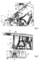
- eine schaubildliche Darstellung einer eingebauten Drehmomentstütze mit Strebe und Stützenarm und Befestigung am Längsträger, am Federbeindom und am Nockenwellengehäuse,
- Fig.2
- eine Daraufsicht auf die Drehmomentstütze,
- Fig.3
- eine Vorderansicht der Drehmomentstütze, mit Konsolenstützbock
- Fig.4
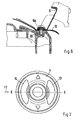
- einen Schnitt durch die Befestigung des Stützenarmes am Nockenwellengehäuse,
- Fig.5
- einen Schnitt durch die Strebe mit Blechwinkel und Befestigung am Längsträger,
- Fig.6
- einen Schnitt durch die Befestigung des Aufbaubocks am Federbeindom und
- Fig.7
- eine Vorderansicht auf das Lager mit nierenförmigen Ausnehmungen.
- Fig.1
- a perspective view of a built-in torque arm with strut and support arm and attachment to the side member, the strut tower and the camshaft housing,
- Fig.2
- a view of the torque arm,
- Figure 3
- a front view of the torque arm, with console support bracket
- Figure 4
- a section through the attachment of the support arm on the camshaft housing,
- Figure 5
- a section through the strut with sheet metal bracket and attachment to the side member,
- Figure 6
- a section through the attachment of the body block on Federbeindom and
- Figure 7
- a front view of the camp with kidney-shaped recesses.
Die Vorrichtung 1 zur Drehmomentabstützung umfasst eine Strebe 3, einen Stützenarm
2, sowie ein verbindendes elastisches Lager 4. Der Stützenarm 2 ist unter
Zwischenschaltung eines Gelenklagers 11 über einen Konsolenstützbock 5 mit einem
Nockenwellengehäuse 6 und die Strebe 3 ist über einen Blechwinkel 7 mit einem
Längsträger 8 des Fahrzeugaufbaus verbunden. Über einen Aufnahmebock 9 wird die
Strebe 3 am Federbeindom 10 des Fahrzeugs abgestützt.The torque-assisting
Die Strebe 3 und der Stützenarm 2 der Drehmomentstütze 1 sind etwa in einer
horizontalen Ebene angeordnet und erstrecken sich zur Abstützung von Drehmomenten
des Aggregats und zur Aufnahme von Leerlaufschwingungen von der Zylinderkopfhaube
12 bis zu einem seitlich des Fahrzeugaufbaus angeordneten Längsträger 8, wie Fig. 2
näher zeigt.The
Die Strebe 3 und der Stützenarm 2 sind über ein elastisches Lager 4 miteinander
verbunden, das in einem Auge des Stützenarmes 2 gehalten wird und auf einem
Lagerbolzen abgestützt ist, der mit der Strebe 3 und dem Aufnahmebock 9 verbunden
ist. Die Strebe 3 und der Aufnahmebock 9 können statt aus einem Blechprofil bestehend
auch aus einem Fußteil hergestellt sein.The
Das Lager 4 im Stützenarm 2 weist nierenförmige Ausnehmungen 13, 14 auf, die in
Richtung der Druckbelastung und/oder Zugbelastung F2 des Stützenarmes 2
hintereinander liegend in einer horizontalen Ebene X - X angeordnet sind. Durch diese
Anordnung der Ausnehmungen 13, 14 werden die Leerlaufbewegungen des Aggregats
nicht auf die Karosserie bzw. den Längsträger 8 übertragen. Es ergibt sich durch die
Ausnehmungen eine stark progressive Kennlinie des Lagers 4 bei den Druck- bzw.
Zugbelastungen.The bearing 4 in the
Das dem elastischen Lager 4 abgekehrte freie Ende des Stützenarmes 2 ist über ein
hartes Gummilager 11 bzw. ein Kugelgelenk mit dem Konsolenstützbock 5 verbunden,
welches lediglich die Drehbewegung beim Federn des Aggregats zulassen soll.The the
Der mit dem Gummilager 11 verbundene Konsolenstützbock 5 ist, wie Fig. 4 näher zeigt,
mit seinem Fuß 15 am Nockenwellengehäuse 6, beispielsweise in Aufnahmen 16, 17
fixiert und über Schrauben festgesetzt, die nur als Linien dargestellt sind.The
Die Strebe 3 ist einerseits mit dem Aufnahmebock 9 und andererseits über den
Blechwinkel 7 starr am Federbeindom 10 bzw. am Längsträger 8 der Aufbaustruktur
befestigt. Hierzu weist der Blechwinkel 7 zwei den Träger 8 von oben und von unten
übergreifende Schenkel 7a, 7b auf, so dass die Strebe 3 eine Lage zum Träger 8
einnimmt, welche eine Krafteinleitung von der Strebe 3 in den Träger 8 etwa mittig in
Pfeilrichtung Z bewirkt.The
Die Verbindung des Aufnahmebocks 9 mit dem Federbeindom 10 erfolgt über eine
Abstellung 9a, welche am Federbeindom 10 aufliegt und mittels einer Schraube 20
verbunden wird.The connection of the receiving
Claims (7)
- A device for supporting the torque of an internal-combustion engine in a vehicle by means of at least one torque support (1) which is arranged in the vehicle between the internal-combustion engine and a body member (8) of the vehicle and is connected to the body structure, wherein the torque support (1) is bipartite and comprises a support arm (2) and a strut (3) which are connected to one another via a bearing (4), characterised in that the torque support is arranged transversely in the vehicle, and the support arm (2) is connected at one end to a cylinder-head cover (12) and/or a camshaft housing (6) via a rigid articulated bearing (11) with a pivoting axis, and at the other end to the strut (3) via a fixed resilient bearing (4) with a further pivoting axis, the end of the strut (3) being fixed to the member (8) of the body structure of the vehicle.
- A device according to claim 1, characterised in that the support arm (2) is held with one end in the articulated bearing (11) on the cylinder-head cover (12) and/or on the camshaft housing (6) via a supporting frame (5) and is supported with its remote other end in the resilient bearing (4) which is fixedly mounted on a suspension-strut dome (10) via a mounting frame (9).
- A device according to claim 2, characterised in that the strut (3) is rigidly connected to the mounting frame (9) and is supported, by an end facing the support arm (2), in the resilient bearing (4) which is held in the mounting frame (9).
- A device according to claim 2 or 3, characterised in that the resilient bearing (4) is arranged in a bearing eye of the support arm (2), and this arm (2) lies between the mounting frame (9) and the strut (3), and the mounting frame (9) engages over the strut (3) and fastens it by means of two arms (9c, 9d) and has a base surface (9a) for fastening to the suspension-strut dome (10).
- A device according to any one of claims 2 to 4, characterised in that the supporting frame (5) is fixable by its base (16 [sic - 15]) in receptacles (16, 17) of the camshaft housing (6).
- A device according to one or more of the preceding claims, characterised in that the resilient bearing (4) connecting the support arm (2) to the strut (3) is formed as a damping bearing with two kidney-shaped recesses (13, 14) which are arranged so as to lie one behind the other in a horizontal plane (X-X) in the direction of the pressure loading (F2) of the torque support (1).
- A device according to one or more of the preceding claims, characterised in that the strut (3) has at its end an angle iron (7) which is connected to the member (8) of the body structure and has two arms (7a, 7b) engaging over the member (8) from above and from below, and the strut (3) ends upstream of a web of the member (8) so that the force transmission (Z) into the member section takes place substantially centrally.
Applications Claiming Priority (2)
| Application Number | Priority Date | Filing Date | Title |
|---|---|---|---|
| DE10024164A DE10024164B4 (en) | 2000-05-17 | 2000-05-17 | Torque support device for an internal combustion engine |
| DE10024164 | 2000-05-17 |
Publications (3)
| Publication Number | Publication Date |
|---|---|
| EP1155893A2 EP1155893A2 (en) | 2001-11-21 |
| EP1155893A3 EP1155893A3 (en) | 2003-07-02 |
| EP1155893B1 true EP1155893B1 (en) | 2005-07-13 |
Family
ID=7642390
Family Applications (1)
| Application Number | Title | Priority Date | Filing Date |
|---|---|---|---|
| EP01107993A Expired - Lifetime EP1155893B1 (en) | 2000-05-17 | 2001-03-29 | Apparatus for supporting the torque load of an internal combustion engine |
Country Status (6)
| Country | Link |
|---|---|
| US (2) | US6629576B2 (en) |
| EP (1) | EP1155893B1 (en) |
| JP (1) | JP3393864B2 (en) |
| AT (1) | ATE299447T1 (en) |
| DE (2) | DE10024164B4 (en) |
| ES (1) | ES2241707T3 (en) |
Families Citing this family (14)
| Publication number | Priority date | Publication date | Assignee | Title |
|---|---|---|---|---|
| FR2884181B1 (en) * | 2005-04-11 | 2007-06-15 | Renault Sas | ENGINE ASSEMBLY OF A VEHICLE |
| FR2884210B1 (en) * | 2005-04-12 | 2007-06-15 | Hutchinson Sa | DEVICE FOR SUSPENDING AN ENGINE ON A BOGIE CHASSIS |
| DE102005055396A1 (en) | 2005-11-17 | 2007-05-24 | Automotive Group Ise Innomotive Systems Europe Gmbh | Torque crossmember |
| DE102008039479A1 (en) | 2008-08-23 | 2010-02-25 | Dr. Ing. H.C. F. Porsche Aktiengesellschaft | Device for mounting a drive unit in a motor vehicle |
| US8215444B2 (en) * | 2009-07-09 | 2012-07-10 | Ford Global Technologies | Roll restrictor system for an automotive powertrain |
| GB201004473D0 (en) * | 2010-03-17 | 2010-05-05 | Trysome Ltd | Lightweight engine mounting |
| DE102011111236A1 (en) * | 2011-08-20 | 2013-02-21 | GM Global Technology Operations LLC (n. d. Gesetzen des Staates Delaware) | Automotive body |
| US8596403B2 (en) * | 2012-03-22 | 2013-12-03 | Toyota Motor Engineering & Manufacturing North America, Inc. | Motor mounting assemblies for electric vehicles and electric vehicles comprising the same |
| DE102013208231A1 (en) | 2013-05-06 | 2014-11-06 | Mahle International Gmbh | Cylinder head cover |
| US9158868B2 (en) * | 2013-08-22 | 2015-10-13 | GM Global Technology Operations LLC | Vehicle powertrain mounting system and method of designing same |
| US20150158372A1 (en) * | 2013-12-11 | 2015-06-11 | Eric F. DeHesselle | Torque strut |
| DE102013113964A1 (en) * | 2013-12-12 | 2015-06-18 | Dr. Ing. H.C. F. Porsche Aktiengesellschaft | bearing arrangement |
| JP6551200B2 (en) * | 2015-12-02 | 2019-07-31 | スズキ株式会社 | Support device for internal combustion engine for vehicle |
| DE102017209475A1 (en) * | 2017-06-06 | 2018-12-06 | Audi Ag | Aggregate storage for a motor vehicle |
Family Cites Families (27)
| Publication number | Priority date | Publication date | Assignee | Title |
|---|---|---|---|---|
| SE334550B (en) * | 1965-05-11 | 1971-04-26 | Saab Scania Ab | |
| JPS4819963B1 (en) * | 1968-09-24 | 1973-06-18 | ||
| US3841426A (en) * | 1972-12-07 | 1974-10-15 | Fmc Corp | Engine isolation system |
| US3825090A (en) * | 1973-08-08 | 1974-07-23 | Gen Motors Corp | Rotary engine and transmission assembly mounting system |
| FR2265565B1 (en) * | 1974-03-28 | 1977-06-17 | Peugeot & Renault | |
| US4240517A (en) * | 1979-04-13 | 1980-12-23 | General Motors Corporation | Powertrain and independent suspension mounting arrangement for front-wheel-drive vehicle |
| JPS56108307A (en) * | 1980-02-01 | 1981-08-27 | Nissan Motor Co Ltd | Device for supporting engine |
| JPS5863519A (en) * | 1981-10-12 | 1983-04-15 | Nissan Motor Co Ltd | Mounting device of power unit |
| US4518058A (en) * | 1981-12-21 | 1985-05-21 | Moog Automotive, Inc. | Engine torgue resisting strut and vibration damper |
| DE3510335A1 (en) * | 1985-03-22 | 1986-10-16 | Adam Opel AG, 6090 Rüsselsheim | MOTOR VEHICLE |
| US4685531A (en) * | 1986-03-31 | 1987-08-11 | General Motors Corporation | Motor vehicle power train torque strut |
| US5039073A (en) * | 1987-04-06 | 1991-08-13 | Cooper Tire & Rubber Company | Mount for controlling or isolating vibration |
| US4779834A (en) * | 1987-08-07 | 1988-10-25 | General Motors Corporation | Engine displacement limiter |
| SE466996B (en) * | 1987-12-03 | 1992-05-11 | Volvo Ab | DEVICE FOR SUSPENSION OF AN ENGINE IN A VEHICLE |
| DE3808762A1 (en) * | 1988-03-16 | 1989-09-28 | Porsche Ag | BEARING FOR A MOTOR GEAR UNIT |
| JP2678313B2 (en) * | 1989-05-31 | 1997-11-17 | スズキ株式会社 | Engine mounting device |
| DE4209613A1 (en) * | 1991-04-04 | 1992-10-08 | Volkswagen Ag | Aggregate bearing with torque support in motor vehicle - has elastic ring core bearing with surrounding radial support ring |
| US5205374A (en) * | 1991-06-13 | 1993-04-27 | Dana Corporation | Synthetic engine mount strut |
| DE4209316A1 (en) | 1992-03-23 | 1993-09-30 | Krupp Industrietech | Layable bridge |
| US5570757A (en) * | 1993-11-22 | 1996-11-05 | Textron Inc. | Engine mounting system for a car |
| FR2731184B1 (en) * | 1995-03-02 | 1997-06-27 | Peugeot | DEVICE FOR SUSPENDING A MOTOR-PROPELLER ON THE STRUCTURE OF A MOTOR VEHICLE |
| FR2736008B1 (en) * | 1995-06-29 | 1997-08-22 | Peugeot | SUSPENSION MODULE OF A MOTOR-PROPELLER ON THE STRUCTURE OF A MOTOR VEHICLE |
| DE19731128C2 (en) * | 1997-07-19 | 1999-09-23 | Volkswagen Ag | Pendulum support for an assembly in a motor vehicle and elastic assembly bearing |
| JPH10114226A (en) * | 1997-09-19 | 1998-05-06 | Suzuki Motor Corp | Engine mounting device |
| DE19839521C1 (en) * | 1998-08-29 | 2000-03-09 | Daimler Chrysler Ag | Stem structure for a motor vehicle |
| US6234268B1 (en) * | 2000-01-14 | 2001-05-22 | Daimlerchrysler Corporation | Torque strut with end weights |
| US6390223B1 (en) * | 2000-01-14 | 2002-05-21 | Daimlerchrysler Corporation | Engine/transmission combination mounting system |
-
2000
- 2000-05-17 DE DE10024164A patent/DE10024164B4/en not_active Expired - Fee Related
-
2001
- 2001-03-29 EP EP01107993A patent/EP1155893B1/en not_active Expired - Lifetime
- 2001-03-29 DE DE50106717T patent/DE50106717D1/en not_active Expired - Lifetime
- 2001-03-29 ES ES01107993T patent/ES2241707T3/en not_active Expired - Lifetime
- 2001-03-29 AT AT01107993T patent/ATE299447T1/en not_active IP Right Cessation
- 2001-05-14 JP JP2001143605A patent/JP3393864B2/en not_active Expired - Fee Related
- 2001-05-17 US US09/858,925 patent/US6629576B2/en not_active Expired - Fee Related
-
2003
- 2003-08-15 US US10/641,081 patent/US20040031638A1/en not_active Abandoned
Also Published As
| Publication number | Publication date |
|---|---|
| US20020011376A1 (en) | 2002-01-31 |
| ES2241707T3 (en) | 2005-11-01 |
| JP2001328440A (en) | 2001-11-27 |
| ATE299447T1 (en) | 2005-07-15 |
| JP3393864B2 (en) | 2003-04-07 |
| DE50106717D1 (en) | 2005-08-18 |
| EP1155893A3 (en) | 2003-07-02 |
| EP1155893A2 (en) | 2001-11-21 |
| US6629576B2 (en) | 2003-10-07 |
| DE10024164A1 (en) | 2001-11-29 |
| DE10024164B4 (en) | 2004-07-01 |
| US20040031638A1 (en) | 2004-02-19 |
Similar Documents
| Publication | Publication Date | Title |
|---|---|---|
| EP1076783B1 (en) | Bearing for a shock absorber strut or a pneumatic spring | |
| DE10024164B4 (en) | Torque support device for an internal combustion engine | |
| DE1455649A1 (en) | Suspension for motor vehicles | |
| EP1512560B1 (en) | Adjustable chassis | |
| EP1970293B1 (en) | Vehicle | |
| DE3006705A1 (en) | ARRANGEMENT OF A DRIVE SYSTEM FOR A VEHICLE WITH FRONT WHEEL DRIVE AND SINGLE WHEEL SUSPENSION OF THE FRONT WHEELS | |
| EP2199121B1 (en) | Wheel suspension for motor vehicles | |
| DE69919140T2 (en) | FASTENING ARRANGEMENT OF A DRIVE UNIT FOR VEHICLES | |
| DE3939192C2 (en) | JOINT CONNECTION BETWEEN THE TILTING CYLINDER AND THE TILTABLE CAB OF A TRUCK | |
| DE1555975A1 (en) | Storage for a tiltable driver's cabin of motor vehicles | |
| EP0265675B1 (en) | Assembly comprising an auxiliary chassis with pivotally mounted suspension arms | |
| EP1293404B1 (en) | Wiper arm and windscreen wiper device, in particular for a vehicle | |
| DE102017220203A1 (en) | Assembly storage for a drive unit in a vehicle | |
| DE19960457C2 (en) | Bearing for a shock absorber leg or an air spring of a wheel suspension | |
| DE19827864C1 (en) | Wheel suspension for a motor vehicle | |
| DE102017211277A1 (en) | Wheel suspension for a motor vehicle | |
| DE10029881B4 (en) | fork-lift truck | |
| DE69713696T2 (en) | Suspension device, in particular for motor vehicles | |
| DE3741465A1 (en) | PIN HANGER OF A TELESCOPIC SHOCK ABSORBER OR A SPRING FOR MOTOR VEHICLES | |
| DE19748778B4 (en) | Bearing device for a power plant test bench | |
| EP1206365B1 (en) | Suspension for a drive unit | |
| DE102018207616A1 (en) | Wheel suspension for a motor vehicle | |
| DE19907668A1 (en) | Belt drive for vehicle engine, in which belt pulley can turn round first axis | |
| DE102016004703A1 (en) | Wheel suspension for a motor vehicle | |
| DE2722926A1 (en) | Elastic mounting for radiator - uses transverse elastic shackles to hold base and stabilising strut to body on top |
Legal Events
| Date | Code | Title | Description |
|---|---|---|---|
| PUAI | Public reference made under article 153(3) epc to a published international application that has entered the european phase |
Free format text: ORIGINAL CODE: 0009012 |
|
| AK | Designated contracting states |
Kind code of ref document: A2 Designated state(s): AT BE CH CY DE DK ES FI FR GB GR IE IT LI LU MC NL PT SE TR |
|
| AX | Request for extension of the european patent |
Free format text: AL;LT;LV;MK;RO;SI |
|
| PUAL | Search report despatched |
Free format text: ORIGINAL CODE: 0009013 |
|
| AK | Designated contracting states |
Designated state(s): AT BE CH CY DE DK ES FI FR GB GR IE IT LI LU MC NL PT SE TR |
|
| AX | Request for extension of the european patent |
Extension state: AL LT LV MK RO SI |
|
| 17P | Request for examination filed |
Effective date: 20040102 |
|
| AKX | Designation fees paid |
Designated state(s): AT DE ES FR GB IT |
|
| 17Q | First examination report despatched |
Effective date: 20040830 |
|
| GRAP | Despatch of communication of intention to grant a patent |
Free format text: ORIGINAL CODE: EPIDOSNIGR1 |
|
| GRAS | Grant fee paid |
Free format text: ORIGINAL CODE: EPIDOSNIGR3 |
|
| GRAA | (expected) grant |
Free format text: ORIGINAL CODE: 0009210 |
|
| AK | Designated contracting states |
Kind code of ref document: B1 Designated state(s): AT DE ES FR GB IT |
|
| REG | Reference to a national code |
Ref country code: GB Ref legal event code: FG4D Free format text: NOT ENGLISH |
|
| REF | Corresponds to: |
Ref document number: 50106717 Country of ref document: DE Date of ref document: 20050818 Kind code of ref document: P |
|
| REG | Reference to a national code |
Ref country code: ES Ref legal event code: FG2A Ref document number: 2241707 Country of ref document: ES Kind code of ref document: T3 |
|
| GBT | Gb: translation of ep patent filed (gb section 77(6)(a)/1977) | ||
| ET | Fr: translation filed | ||
| PLBE | No opposition filed within time limit |
Free format text: ORIGINAL CODE: 0009261 |
|
| STAA | Information on the status of an ep patent application or granted ep patent |
Free format text: STATUS: NO OPPOSITION FILED WITHIN TIME LIMIT |
|
| 26N | No opposition filed |
Effective date: 20060418 |
|
| PGFP | Annual fee paid to national office [announced via postgrant information from national office to epo] |
Ref country code: ES Payment date: 20080328 Year of fee payment: 8 |
|
| PGFP | Annual fee paid to national office [announced via postgrant information from national office to epo] |
Ref country code: GB Payment date: 20080320 Year of fee payment: 8 |
|
| PGFP | Annual fee paid to national office [announced via postgrant information from national office to epo] |
Ref country code: AT Payment date: 20080314 Year of fee payment: 8 |
|
| REG | Reference to a national code |
Ref country code: ES Ref legal event code: PC2A |
|
| REG | Reference to a national code |
Ref country code: FR Ref legal event code: TP |
|
| PG25 | Lapsed in a contracting state [announced via postgrant information from national office to epo] |
Ref country code: AT Free format text: LAPSE BECAUSE OF NON-PAYMENT OF DUE FEES Effective date: 20090329 |
|
| GBPC | Gb: european patent ceased through non-payment of renewal fee |
Effective date: 20090329 |
|
| REG | Reference to a national code |
Ref country code: FR Ref legal event code: CD |
|
| PG25 | Lapsed in a contracting state [announced via postgrant information from national office to epo] |
Ref country code: GB Free format text: LAPSE BECAUSE OF NON-PAYMENT OF DUE FEES Effective date: 20090329 |
|
| REG | Reference to a national code |
Ref country code: ES Ref legal event code: FD2A Effective date: 20090330 |
|
| PG25 | Lapsed in a contracting state [announced via postgrant information from national office to epo] |
Ref country code: ES Free format text: LAPSE BECAUSE OF NON-PAYMENT OF DUE FEES Effective date: 20090330 |
|
| PGFP | Annual fee paid to national office [announced via postgrant information from national office to epo] |
Ref country code: IT Payment date: 20100327 Year of fee payment: 10 |
|
| REG | Reference to a national code |
Ref country code: FR Ref legal event code: TP |
|
| PGFP | Annual fee paid to national office [announced via postgrant information from national office to epo] |
Ref country code: FR Payment date: 20110404 Year of fee payment: 11 |
|
| PG25 | Lapsed in a contracting state [announced via postgrant information from national office to epo] |
Ref country code: IT Free format text: LAPSE BECAUSE OF NON-PAYMENT OF DUE FEES Effective date: 20110329 |
|
| REG | Reference to a national code |
Ref country code: FR Ref legal event code: ST Effective date: 20121130 |
|
| PG25 | Lapsed in a contracting state [announced via postgrant information from national office to epo] |
Ref country code: FR Free format text: LAPSE BECAUSE OF NON-PAYMENT OF DUE FEES Effective date: 20120402 |
|
| PGFP | Annual fee paid to national office [announced via postgrant information from national office to epo] |
Ref country code: DE Payment date: 20180403 Year of fee payment: 18 |
|
| REG | Reference to a national code |
Ref country code: DE Ref legal event code: R119 Ref document number: 50106717 Country of ref document: DE |
|
| PG25 | Lapsed in a contracting state [announced via postgrant information from national office to epo] |
Ref country code: DE Free format text: LAPSE BECAUSE OF NON-PAYMENT OF DUE FEES Effective date: 20191001 |