EP1155955B1 - Panneau d'écoutille - Google Patents
Panneau d'écoutille Download PDFInfo
- Publication number
- EP1155955B1 EP1155955B1 EP01870098A EP01870098A EP1155955B1 EP 1155955 B1 EP1155955 B1 EP 1155955B1 EP 01870098 A EP01870098 A EP 01870098A EP 01870098 A EP01870098 A EP 01870098A EP 1155955 B1 EP1155955 B1 EP 1155955B1
- Authority
- EP
- European Patent Office
- Prior art keywords
- hatch
- hatch cover
- beams
- cover according
- flap
- Prior art date
- Legal status (The legal status is an assumption and is not a legal conclusion. Google has not performed a legal analysis and makes no representation as to the accuracy of the status listed.)
- Revoked
Links
- 230000000284 resting effect Effects 0.000 claims description 5
- 239000013013 elastic material Substances 0.000 claims description 2
- 239000000463 material Substances 0.000 description 7
- 230000000694 effects Effects 0.000 description 4
- 238000004026 adhesive bonding Methods 0.000 description 2
- 229910052751 metal Inorganic materials 0.000 description 2
- 239000002184 metal Substances 0.000 description 2
- 230000002787 reinforcement Effects 0.000 description 2
- XLYOFNOQVPJJNP-UHFFFAOYSA-N water Substances O XLYOFNOQVPJJNP-UHFFFAOYSA-N 0.000 description 2
- 229910000838 Al alloy Inorganic materials 0.000 description 1
- 241001481833 Coryphaena hippurus Species 0.000 description 1
- 239000004411 aluminium Substances 0.000 description 1
- 229910052782 aluminium Inorganic materials 0.000 description 1
- XAGFODPZIPBFFR-UHFFFAOYSA-N aluminium Chemical compound [Al] XAGFODPZIPBFFR-UHFFFAOYSA-N 0.000 description 1
- 239000003000 extruded plastic Substances 0.000 description 1
- 239000000203 mixture Substances 0.000 description 1
- 239000004033 plastic Substances 0.000 description 1
- 230000000717 retained effect Effects 0.000 description 1
- 239000010935 stainless steel Substances 0.000 description 1
- 229910001220 stainless steel Inorganic materials 0.000 description 1
- 238000003466 welding Methods 0.000 description 1
Images


Classifications
-
- B—PERFORMING OPERATIONS; TRANSPORTING
- B63—SHIPS OR OTHER WATERBORNE VESSELS; RELATED EQUIPMENT
- B63B—SHIPS OR OTHER WATERBORNE VESSELS; EQUIPMENT FOR SHIPPING
- B63B19/00—Arrangements or adaptations of ports, doors, windows, port-holes, or other openings or covers
- B63B19/12—Hatches; Hatchways
- B63B19/14—Hatch covers
- B63B19/16—Hatch covers with detachable boards
Definitions
- the invention relates to a nestable hatch cover, in particular of the "Frisian cap” type, for covering a hatchway giving access to a vessel's hold, which hatchway is provided with a hatch coaming having two hatch beams situated opposite each other, which hatch cover has two end parts situated opposite each other, each provided underneath with a bearing surface which is designed to rest upon said hatch beams, each forming an outermost end of the hatch cover and each optionally provided with a locking flap.
- there are different types of such hatchway hoods including, for example, the so-called "Frisian cap” hatchway hoods.
- the latter are made of sheet material which is shaped in such a way that a hatch cover surface and gutters situated next to it are formed.
- a general feature of the known hatch covers is that they have a projecting lip at both ends, under which lip the lifting scoop of a hatch cover truck can engage, in order to lift and move the hatch covers during stacking.
- the hatch covers in practice generally project a minimum distance of 8 - 10 cm beyond the hatch beams.
- a major disadvantage of this is that, because of these projecting hatch covers, the clear width of the adjacent gangways is reduced.
- This clear width must, however, be as great as possible, in order to allow a comfortable passage, and must be at least greater than a minimum value, in order to prevent accidents.
- regulations stipulating a specific clear width.
- the object of the invention is then to provide a new nestable hatch cover which does not have to project so far beyond the hatch beams in order to be placed easily and in a reliable manner on said hatch beams.
- the hatch cover according to the invention is characterized in that the bearing surfaces by means of which the hatch cover rests upon the hatch beams are each bounded on their outside by at least one projection projecting below said bearing surfaces, which projection in each case is situated substantially at one of the abovementioned outermost extremities and, when the hatch cover is resting with its bearing surfaces upon the hatch beams, the projections have slanting insides which face the outside of the hatch beams and flare out downwards from the respective hatch beam.
- a difference between the edges on the hatch cover disclosed in BE-A-680,230 and the projections on the hatch cover according to the invention is that in the hatch cover according to the invention the projections have slanting insides which face the outside of the hatch beams and flare out downwards from the respective hatch beam whilst the corresponding edges in the hatch cover disclosed in BE-A-680,230 are directed towards the outside of the hatch beams.
- the hatch covers according to the invention a centring effect is thus obtained with the result that the hatch covers can be placed more easily on the hatch beams.
- the abovementioned projection is provided in such a way that it butts against the outside of the hatch beams with a predetermined play.
- the hatch cover is designed to be fixed on said hatch beams by means of locking flaps, and said locking flaps are hook-shaped at the top, so that they act upon the hatch cover above the bearing surface of the hatch cover, more particularly above the hatch beams upon which the hatch cover is placed.
- This shape of the locking flaps also helps to ensure that the distance which the hatch cover projects beyond the hatch beams can be limited to the maximum extent.
- the bearing surface with which the hatch cover rests upon the respective hatch beam is at least partially formed by a sheet part which forms a top surface of the hatch cover at both ends of the hatch cover.
- the thickness of the hatch cover at the level of the hatch beam is thus limited to the thickness of the sheet material from which the bearing material, and possibly the entire hatch cover, is made.
- a limited thickness has the advantage that persons can walk more easily along the gangway, and it can be important for fulfilling the stipulated minimum gangway width. It is in fact usually stipulated in practice that from a certain height upwards the gangway must be broader, in order to allow safe movement of persons along it. However, in order to obtain the maximum hold capacity, the hatch beams generally already have this maximum height.
- the hatch cover 1 according to the invention can be in different forms, for example with or without catway 2 in the centre of the hatch cover (see Figures 3 and 4), but is generally provided for covering a hatchway which gives access to a vessel's hold 3 and is bounded by a hatch coaming having two hatch beams 4 situated opposite each other.
- a gangway 6 is provided in each case between said hatch beams 4 and the outside wall 5 of the vessel.
- the object of the invention is to provide a new hatch cover which only has to project a minimal distance beyond the hatch beams 4, so that the clear width of the gangways 6 can thus remain at a maximum level.
- FIG. 1 A preferred embodiment of such a hatch cover is shown in Figures 1 to 6.
- Said hatch cover 1 comprises a top hatch cover surface 7 and gutters 8 extending next to said hatch cover surface 7 which have a bottom 9 and a slanting gutter wall 10 extending between the top hatch cover surface 7 and said bottom.
- the top hatch cover surface 7 can be split by so-called inner gutters 11 (see, for example Figure 14) into two or more parts.
- the whole of the top hatch cover surfaces 7 and gutters 8 is preferably made of a sheet material by folding, welding or possibly forming in another way, for example by gluing, pressure joining etc., and forms the basic part of the hatch cover.
- the sheet material is generally a metal such as an aluminium alloy or stainless steel.
- two end parts 12, situated opposite each other, are also welded against this basic part of the hatch cover, more specifically along the welded seam 13.
- Said end parts 12 each have underneath a bearing surface 14, which is designed to rest upon the hatch beams 4.
- the latter are preferably covered with an elastic material, in particular with a rubber layer 15.
- the ends 12 may, if desired, be connected to the basic part in other ways, for example by gluing, with rivets, with snap-in systems, or by folding them integrally from the same sheet as the basic part.
- the top side of the end parts 12 is preferably connected by way of a slanting surface 16 to the top hatch cover surface 7 in such a way that a so-called "dolphin hatch cover" is obtained.
- the bearing surface 14 of such hatch covers can thus extend substantially at the level of the bottoms 9 of the gutters 8 without the stack height being increased (see Figure 6).
- the fact is that, as a result of the slanting arrangement of the surface 16, the nestability of the hatch cover is retained.
- the advantage of this embodiment is that the end parts 12 have a flat underside and can thus rest upon a flat hatch beam 4.
- the top hatch cover surface 7, on the other hand, runs to the outermost extremities of the hatch cover, and the bearing surface 14 of the end parts 12 is situated above the bottom 9 of the gutters 8 in such a way that so-called gutter ledge holes 17 have to be made in the hatch beams 4 for these gutters 8.
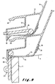
- the bearing surface 14 by means of which the hatch cover rests with an end part 12 upon the hatch beams 4 forms the underside of a hollow reinforcement structure 18.
- a flap aperture 19 for allowing a locking flap 20 to be passed through, by means of which flap the hatch cover can be fixed on the hatch beams 4.
- said flap has on the top a T-shaped end 21, by means of which it sits hooked securely behind the aperture 19 in the transverse bracing structure 18.
- the flap is provided with an elongated aperture 22, by means of which it can be slipped over an eye 23 on the hatch beam 4 and locked.
- the flap When the flap is released it can, as shown in Figure 6, be partially stored in the transverse bracing structure 18, its T-shaped end 21 hooking behind a raised edge 24. Because of this storage facility, the transverse brace is in practice also called the flap box. In order to fit and, if necessary, replace the locking flaps 20, apertures which can be closed off by means of a plate 29 and bolts 39 are provided in the rear of the flap boxes 18.
- two or more lifting apertures 25 are further provided, through which apertures two teeth of the fork of a hatch cover truck can be inserted into said transverse bracing structure, in order to lift the hatch cover.
- Notches 26 are further provided below these lifting apertures 25, in such a way that if several hatch covers are stacked on each other as shown in Figure 6, this full stack or a part thereof can be picked up by the teeth of a hatch cover truck through the notches 26 and the apertures 25.
- the object of the invention is to provide a hatch cover in which the end parts resting upon the hatch beams are formed in such a way that the distance that the ends of the hatch cover projects beyond the hatch beams can be limited by comparison with the known hatch covers.
- the bearing surfaces 14 below the end parts 12 are bounded on their outside by at least one projection 27 projecting below said bearing surfaces 14, said projection in each case being situated substantially at one of the outermost extremities of the hatch cover.
- the projection is formed by a downward projecting edge 27, in which the notches 26 for the teeth of the hatch cover truck are made.
- Said edge 27 forms part of the slanting sides of the hatch cover and thus has a slanting inside which widens downwards from the hatch beam 4. In this way a centring effect is obtained, with the result that the hatch cover can be placed easily on the hatch beams, despite the fact that the edge 27 butts against the outside of the hatch beam 4 with a predetermined minimum play.
- the edge 27 butts fully against the hatch beam, but at other points, where the distance between the two hatch beams is slightly smaller, some distance will be produced between the hatch beam and the edge.
- the hatch cover projects only a minimal distance beyond the hatch beams, in particular only a distance of 1.5 to 2.5 cm. It will be clear that if the centring effect is reduced by placing the edges 27 in a straighter position, the distance that the hatch cover projects beyond the hatch beams can be limited even further.
- a special locking flap 20 is used, namely a locking flap 20 which is hook-shaped at the top, in such a way that it can act upon the hatch cover above the bearing surface 14 or, in other words, above the hatch beam.
- the flap aperture 19 is provided laterally in the hollow transverse bracing structure 18 and the flap by means of which the hatch cover is fixed on the hatch beams extends through said lateral aperture 19.
- a straight flap 20 is used, which flap comes out of the flap box 18 at the bottom. Notwithstanding this straight flap 20, the distance that the hatch cover projects beyond the hatch beam is still limited, owing to the fact that the downward projecting edge 27 alongside the bearing surface 14 of the hatch cover determines the outermost extremity of the hatch cover.
- the gripping means provided in this embodiment is a lifting lip 28, which extends, however, between the outermost extremities of the hatch cover.
- a stack of hatch covers can be lifted by means of a conventional hatch cover truck with a through-running lifting scoop.
- Figure 9 shows a further variant embodiment, which differs from the previous embodiment in that a slanting surface 30 is provided on the inside of the edge 27 in such a way that again a centring effect is obtained.
- the edge 27 and the slanting surface 30 are interrupted in such a way that the hatch cover still only has to project the same minimal distance beyond the hatch beams as in the preceding embodiment.
- the width of the slanting surface is in fact limited substantially to the thickness of the locking flap 20.
- the edge 27 could be raised further if desired, in which case notches then have to be made in said edge 27, for picking up a stack of hatch covers by means of a hatch cover truck with two teeth which can engage in said notches below the lifting lip 28.
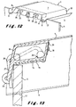
- the bearing surface 14 with which the hatch cover rests upon the hatch beam 4 is in each case formed by the underside of the transverse bracing structure or flap box 18.
- said bearing surface 14 is now formed by a sheet part 31, which at the end sections 12 forms the top surface of the hatch cover.
- This has the advantage that a greater clear gangway width is obtained directly above the hatch beam.
- this brace in fact still serves as a flap box.
- locking flaps 20 which are composed of at least two parts, which pivot relative to each other. They can be, for example, a chain.
- the top part 32 is, however, preferably formed by a straight part, as shown, provided with the T-shaped end 21 and connected by way of a pivot pin 33 in a pivoting manner to the bottom part 34.
- Said bottom part 34 can again have a hook-shaped top end, by means of which it acts upon the hatch cover 1 above the hatch beams 4.
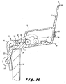
- FIG. 10 Another way of fixing the hatch cover according to Figure 10 on the hatch beams 4 is to make use of locking flaps 20 which are no longer fixed to the hatch cover itself, but to the hatch beams 4.
- a flap 20 is illustrated in Figure 11, in which, however, the flap again engages in a hollow transverse bracing structure 18.
- the flap 20 has on the top a hook-shaped end 35, by means of which it can grip behind a raised edge 36 of the hatch cover, more particularly again above the bearing surface 14 with which the hatch cover rests upon the hatch beam 4.
- the locking flap 20 has an elongated aperture 37, by means of which in a replaceable manner it is fixed around an eye, pin or hook 38 fixed on the hatch beam 4, more particularly in such a way that it can move up and down.
- the locking flap In the bottom position, illustrated by dashed and dotted line, the locking flap can then be blocked by means of a pin (not shown) below the eye 38.
- a pin (not shown) below the eye 38.
- a raised edge 36 need be provided on the sheet part 31 in Figure 10, this being at least at the position of the gripping point of the locking flap on the hatch cover.
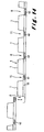
- FIG 14 finally, yet another possible hatch cover type with two outer gutters 8 and one inner gutter 11 is illustrated, the flap box 18 running on over the inner gutters 11 and, for the so-called top hatch covers, also over the outer gutters 8.
- 11 only apertures 40 for allowing through water are provided in the flap box 18.
- These apertures may also, if desired, serve to lift the hatch cover, since the teeth of the hatch cover truck can also be designed to be inserted into these apertures 40. If it is desired to use these apertures 40 for that purpose, it is, however, preferable to provide the hatch cover with at least two inner gutters 11 or, in other words, with at least three hatch cover surfaces, in such a way that the hatch cover can be lifted more easily in a stable manner.
- transverse braces instead of making the transverse braces run on over the inner gutters, it is possible to obtain the same advantage by providing transverse braces between the side walls of the inner gutters 11, in particular round or flat bars, below which the aperture 40 in which the teeth of the hatch cover truck can engage is then formed.
- the gripping means for lifting the hatch cover could also be formed by, for example, eyes or rings on top of the ends of the hatch cover.
- the flap boxes do not have to be made of metal, but could, if desired, also be made of plastic.
- use can also be made here of extruded plastic or aluminium sections, instead of starting from sheets that then have to be folded.
Landscapes
- Chemical & Material Sciences (AREA)
- Engineering & Computer Science (AREA)
- Combustion & Propulsion (AREA)
- Mechanical Engineering (AREA)
- Ocean & Marine Engineering (AREA)
- Laying Of Electric Cables Or Lines Outside (AREA)
- Stackable Containers (AREA)
- Closures For Containers (AREA)
- Cable Accessories (AREA)
- Mechanical Pencils And Projecting And Retracting Systems Therefor, And Multi-System Writing Instruments (AREA)
- Motor Or Generator Frames (AREA)
- Vehicle Step Arrangements And Article Storage (AREA)
- Containers Having Bodies Formed In One Piece (AREA)
- Moulding By Coating Moulds (AREA)
Claims (18)
- Panneau d'écoutille (1), en particulier du type « bonnet frison », pour couvrir une écoutille donnant accès à la cale (3) d'un vaisseau, laquelle écoutille est pourvue d'une hiloire d'écoutille ayant deux galiotes (4) situées en face l'une de l'autre, lequel panneau d'écoutille (1) a deux parties terminales (12) situées l'une en face de l'autre, chacune étant pourvue en dessous d'une surface d'appui (14) qui est conçue pour reposer sur lesdites galiotes (4) chacune formant une extrémité extérieure du panneau d'écoutille (1) et chacune étant pourvue facultativement d'une patte de verrouillage (20), caractérisé en ce que lesdites surfaces d'appui (14) sont chacune limitées sur leur extérieur par au moins une saillie (27) s'avançant en dessous desdites surfaces d'appui (14), laquelle saillie (27) est, dans chaque cas, située sensiblement à une des extrémités extérieures susmentionnées et, quand le panneau d'écoutille (1) repose par ses surfaces d'appui (14) sur les galiotes (4), les saillies (27) ont des intérieurs en oblique qui font face à l'extérieur des galiotes (4) et s'évasent vers le bas à partir de la galiote (4) concernée.
- Panneau d'écoutille selon la revendication 1, caractérisé en ce que lesdites saillies (27) sont formées chacune par un bord (27) faisant saillie vers le bas.
- Panneau d'écoutille selon la revendication 2, caractérisé en ce que des encoches (26) sont faites en bas dans lesdits bords (27).
- Panneau d'écoutille selon la revendication 2 ou 3, caractérisé en ce que lesdits bords (27) faisant saillie vers le bas forment les extrémités extérieures du panneau d'écoutille (1).
- Panneau d'écoutille selon une des revendications 1 à 4, caractérisé en ce que lesdites saillies (27) déterminent les extrémités extérieures du panneau d'écoutille (1), et en ce que le panneau d'écoutille (1) est tel qu'il peut être fixé sur lesdites galiotes (4) au moyen de pattes de verrouillage (20), lesdites pattes de verrouillage (20) dans l'état fixé du panneau d'écoutille (1) s'étendant à l'extérieur des extrémités extérieures du panneau d'écoutille (1) et buttant pratiquement contre l'extrémité extérieure concernée ou lesdites pattes de verrouillage (20) dans l'état fixé s'étendant plus vers l'intérieur, de préférence à l'intérieur des extrémités extérieures du panneau d'écoutille (1).
- Panneau d'écoutille selon une des revendications 1 à 5, caractérisé en ce que les deux parties terminales (12) sont pourvues de moyens de préhension (25, 28) pour attraper le panneau d'écoutille (1), lesquels moyens de préhension (25, 28) sont situés entre lesdites extrémités extérieures du panneau d'écoutille (1).
- Panneau d'écoutille selon la revendication 6, caractérisé en ce que lesdits moyens de préhension (25, 28) comprennent une lèvre de levage (28).
- Panneau d'écoutille selon la revendication 6, caractérisé en ce qu'il comprend au moins deux surfaces (7) de panneau d'écoutille séparées l'une de l'autre par une gouttière intérieure (11), lesdits moyens de préhension comprenant une connexion transversale prévue dans la gouttière intérieure (11) au niveau desdites parties terminales (12).
- Panneau d'écoutille selon une des revendications 1 à 8, caractérisé en ce que ladite surface d'appui (14) est formée au moins en partie par une face inférieure d'une structure de renforcement transversale (18) qui est prévue sur les parties terminales (12) du panneau d'écoutille (1).
- Panneau d'écoutille selon les revendications 6 et 8, caractérisé en ce que lesdits moyens de préhension (25, 28) comprennent des ouvertures de levage (25) prévues dans ladite structure de renforcement transversale (18).
- Panneau d'écoutille selon la revendication 9 ou 10, caractérisé en ce qu'il est prévu qu'il soit fixé au moyen des pattes de verrouillage (20) sur lesdites galiotes (4), en ce que ladite structure de renforcement transversale (18) est creuse, et en ce qu'au moins une ouverture (19) pour patte est prévue dans ladite structure de renforcement (18) creuse pour laisser passer une desdites pattes de verrouillage (20) quand le panneau d'écoutille (1) est fixé au moyen de ladite patte de verrouillage (20) sur la galiote (4).
- Panneau d'écoutille selon la revendication 11, caractérisé en ce que l'ouverture (19) pour patte est prévue latéralement dans la structure de renforcement transversale (18) creuse et en ce que, quand le panneau d'écoutille (1) est fixé sur la galiote (4) au moyen de la patte de verrouillage (20), ladite patte de verrouillage (20) s'étend à travers ladite ouverture latérale (19).
- Panneau d'écoutille selon une des revendications 1 à 8, caractérisé en ce que ladite surface d'appui (14) est formée au moins en partie par une partie de tôle (31) qui forme une surface supérieure au niveau desdites parties terminales (12) du panneau d'écoutille (1).
- Panneau d'écoutille selon une des revendications 1 à 13, caractérisé en ce que le panneau d'écoutille (1) est conçu pour être fixé sur lesdites galiotes (4) au moyen de pattes de verrouillage (20), lesdites pattes de verrouillage (20) ont une extrémité supérieure (21) prévue pour entrer en prise de manière amovible avec le panneau d'écoutille (1) et une extrémité inférieure avec laquelle elles sont fixées sur la galiote (4).
- Panneau d'écoutille selon une des revendications 1 à 14, caractérisé en ce qu'il est conçu pour être fixé sur lesdites galiotes (4) au moyen de pattes de verrouillage (20), lesdites pattes de verrouillage (20) étant composées d'au moins deux parties (32, 34) qui pivotent l'une par rapport à l'autre.
- Panneau d'écoutille selon une des revendications 1 à 15, caractérisé en ce qu'il est conçu pour être fixé sur lesdites galiotes (4) au moyen de pattes de verrouillage (20), lesdites pattes de verrouillage (20) étant en forme de crochet au sommet afin qu'elles puissent agir sur le panneau d'écoutille (1) au-dessus de la surface d'appui (14) du panneau d'écoutille (1).
- Panneau d'écoutille selon une des revendications 1 à 16, caractérisé en ce qu'il comprend au moins une surface supérieure (7) de panneau d'écoutille et des gouttières (8) qui s'étendent à côté de ladite surface (7) de panneau d'écoutille et qui ont un fond (9) et une paroi (10) de gouttière s'étendant entre ladite surface supérieure (7) de panneau d'écoutille et ledit fond (9), dans lequel ladite surface d'appui (14) s'étend entre lesdites gouttières sensiblement au niveau des fonds (9) desdites gouttières (8).
- Panneau d'écoutille selon une des revendications 1 à 17, caractérisé en ce que ladite surface d'appui (14) est couverte d'un matériau élastique, en particulier d'une couche de caoutchouc (15).
Applications Claiming Priority (2)
| Application Number | Priority Date | Filing Date | Title |
|---|---|---|---|
| BE200000334 | 2000-05-18 | ||
| BE2000/0334A BE1013711A5 (nl) | 2000-05-18 | 2000-05-18 | Scheepsluik voor het afdekken van een ruimopening. |
Publications (3)
| Publication Number | Publication Date |
|---|---|
| EP1155955A2 EP1155955A2 (fr) | 2001-11-21 |
| EP1155955A3 EP1155955A3 (fr) | 2002-12-11 |
| EP1155955B1 true EP1155955B1 (fr) | 2006-07-19 |
Family
ID=3896533
Family Applications (1)
| Application Number | Title | Priority Date | Filing Date |
|---|---|---|---|
| EP01870098A Revoked EP1155955B1 (fr) | 2000-05-18 | 2001-05-10 | Panneau d'écoutille |
Country Status (4)
| Country | Link |
|---|---|
| EP (1) | EP1155955B1 (fr) |
| AT (1) | ATE333406T1 (fr) |
| BE (1) | BE1013711A5 (fr) |
| DE (1) | DE60121500T2 (fr) |
Cited By (1)
| Publication number | Priority date | Publication date | Assignee | Title |
|---|---|---|---|---|
| EP4180312A1 (fr) * | 2021-11-16 | 2023-05-17 | Blommaert nv | Dispositif d'écoutille coulissant et paroi latérale améliorée pour celui-ci ainsi que procédé de fabrication |
Families Citing this family (1)
| Publication number | Priority date | Publication date | Assignee | Title |
|---|---|---|---|---|
| GB2399544B (en) * | 2003-03-18 | 2006-05-17 | Intelligent Engineering | Profiled hatch covers |
Family Cites Families (9)
| Publication number | Priority date | Publication date | Assignee | Title |
|---|---|---|---|---|
| US2061337A (en) * | 1934-04-16 | 1936-11-17 | John L Taylor | Hatch construction |
| FR785052A (fr) * | 1934-04-18 | 1935-08-01 | Chantier Naval Et Ateliers De | Couvercle d'écoutille |
| US2121386A (en) * | 1936-02-29 | 1938-06-21 | Carl O Rydholm | Hatch fastener |
| DE652633C (de) * | 1936-06-26 | 1937-11-03 | Johannes Meyboom | Lukenabdeckung, insbesondere fuer Flussfahrzeuge |
| DE813350C (de) * | 1950-08-20 | 1951-09-10 | Jakob Graff | Lukendach aus Leichtmetall, Stahl oder Eisen fuer Frachtschiffe der Binnenschiffahrt |
| BE680230A (fr) * | 1965-04-30 | 1966-10-03 | ||
| US3587476A (en) * | 1968-09-16 | 1971-06-28 | Midland Ross Corp | Reinforced fiberglass hatch cover |
| BE899006A (nl) | 1984-02-27 | 1984-06-18 | Blommaert Pv | Verbeterd kapluik voor schepen |
| BE1007947A3 (nl) * | 1994-06-29 | 1995-11-21 | Baeck Arthur Gerard | Scheepsluik. |
-
2000
- 2000-05-18 BE BE2000/0334A patent/BE1013711A5/nl not_active IP Right Cessation
-
2001
- 2001-05-10 DE DE60121500T patent/DE60121500T2/de not_active Expired - Lifetime
- 2001-05-10 EP EP01870098A patent/EP1155955B1/fr not_active Revoked
- 2001-05-10 AT AT01870098T patent/ATE333406T1/de not_active IP Right Cessation
Cited By (2)
| Publication number | Priority date | Publication date | Assignee | Title |
|---|---|---|---|---|
| EP4180312A1 (fr) * | 2021-11-16 | 2023-05-17 | Blommaert nv | Dispositif d'écoutille coulissant et paroi latérale améliorée pour celui-ci ainsi que procédé de fabrication |
| BE1029925B1 (nl) * | 2021-11-16 | 2023-06-19 | Blommaert Nv | Schuifluikinrichting en verbeterde zijwand hiervoor alsook een werkwijze voor de vervaardiging |
Also Published As
| Publication number | Publication date |
|---|---|
| DE60121500D1 (de) | 2006-08-31 |
| EP1155955A3 (fr) | 2002-12-11 |
| BE1013711A5 (nl) | 2002-06-04 |
| DE60121500T2 (de) | 2007-02-22 |
| ATE333406T1 (de) | 2006-08-15 |
| EP1155955A2 (fr) | 2001-11-21 |
Similar Documents
| Publication | Publication Date | Title |
|---|---|---|
| CA2295852C (fr) | Procede et systeme de stockage et de retrait de conteneurs a marchandises, comprenant un ensemble chariot en pontee | |
| US4043285A (en) | Container ship | |
| CA1090725A (fr) | Caisse a poissons | |
| US6109469A (en) | Freight container | |
| EP0926073B1 (fr) | Récipient empilable | |
| US5161690A (en) | Parallellepidepic transport container | |
| KR20260042459A (ko) | 컨테이너 적재 보조장치, 이를 구비한 컨테이너 운반선 및 컨테이너 하역방법 | |
| US6077019A (en) | Cargo container storage and retrieval system and method | |
| EP1155955B1 (fr) | Panneau d'écoutille | |
| EP2262677B1 (fr) | Procédé et cadre de transport pour charger des tourets sur un navire | |
| PL89051B1 (fr) | ||
| EP2036826A2 (fr) | Palette dotée d'un cadre et d'un sac pliables | |
| JP2010184631A (ja) | 船舶 | |
| NL2005948C2 (nl) | Binnenschip voor het transport van containers en/of verplaatsbare kisten. | |
| US4712340A (en) | Decking support means | |
| CA1307215C (fr) | Caisses emboitables, pour boissons | |
| EP0409837B1 (fr) | Bateau avec son systeme de chargement et de dechargement | |
| EP0267168B1 (fr) | Pont supérieur pour navires-citernes | |
| GB2139983A (en) | Pallet frames | |
| WO2001051363A3 (fr) | Recipient renforçable de maniere selective | |
| EP0228419B1 (fr) | Navire porte-conteneur a cellule ouverte ameliore | |
| BE1005252A6 (nl) | Stapelbaar flessenkrat. | |
| KR910001480B1 (ko) | 컨테이너전용 운반선 | |
| CN216469955U (zh) | 一种集装箱 | |
| CA2059773C (fr) | Conteneur parallelepipedique |
Legal Events
| Date | Code | Title | Description |
|---|---|---|---|
| PUAI | Public reference made under article 153(3) epc to a published international application that has entered the european phase |
Free format text: ORIGINAL CODE: 0009012 |
|
| AK | Designated contracting states |
Kind code of ref document: A2 Designated state(s): AT BE CH CY DE DK ES FI FR GB GR IE IT LI LU MC NL PT SE TR |
|
| AX | Request for extension of the european patent |
Free format text: AL;LT;LV;MK;RO;SI |
|
| PUAL | Search report despatched |
Free format text: ORIGINAL CODE: 0009013 |
|
| AK | Designated contracting states |
Kind code of ref document: A3 Designated state(s): AT BE CH CY DE DK ES FI FR GB GR IE IT LI LU MC NL PT SE TR |
|
| AX | Request for extension of the european patent |
Free format text: AL;LT;LV;MK;RO;SI |
|
| RIC1 | Information provided on ipc code assigned before grant |
Free format text: 7B 63B 19/16 A, 7B 63B 19/24 B, 7B 63B 19/14 B |
|
| 17P | Request for examination filed |
Effective date: 20030603 |
|
| AKX | Designation fees paid |
Designated state(s): AT BE CH CY DE DK ES FI FR GB GR IE IT LI LU MC NL PT SE TR |
|
| 17Q | First examination report despatched |
Effective date: 20040303 |
|
| GRAP | Despatch of communication of intention to grant a patent |
Free format text: ORIGINAL CODE: EPIDOSNIGR1 |
|
| GRAS | Grant fee paid |
Free format text: ORIGINAL CODE: EPIDOSNIGR3 |
|
| RAP1 | Party data changed (applicant data changed or rights of an application transferred) |
Owner name: BAECK, ARTHUR GERARD M. |
|
| RIN1 | Information on inventor provided before grant (corrected) |
Inventor name: BAECK, ARTHUR GERARD M. |
|
| GRAA | (expected) grant |
Free format text: ORIGINAL CODE: 0009210 |
|
| AK | Designated contracting states |
Kind code of ref document: B1 Designated state(s): AT BE CH CY DE DK ES FI FR GB GR IE IT LI LU MC NL PT SE TR |
|
| PG25 | Lapsed in a contracting state [announced via postgrant information from national office to epo] |
Ref country code: AT Free format text: LAPSE BECAUSE OF FAILURE TO SUBMIT A TRANSLATION OF THE DESCRIPTION OR TO PAY THE FEE WITHIN THE PRESCRIBED TIME-LIMIT Effective date: 20060719 Ref country code: FI Free format text: LAPSE BECAUSE OF FAILURE TO SUBMIT A TRANSLATION OF THE DESCRIPTION OR TO PAY THE FEE WITHIN THE PRESCRIBED TIME-LIMIT Effective date: 20060719 Ref country code: IT Free format text: LAPSE BECAUSE OF FAILURE TO SUBMIT A TRANSLATION OF THE DESCRIPTION OR TO PAY THE FEE WITHIN THE PRESCRIBED TIME-LIMIT;WARNING: LAPSES OF ITALIAN PATENTS WITH EFFECTIVE DATE BEFORE 2007 MAY HAVE OCCURRED AT ANY TIME BEFORE 2007. THE CORRECT EFFECTIVE DATE MAY BE DIFFERENT FROM THE ONE RECORDED. Effective date: 20060719 Ref country code: LI Free format text: LAPSE BECAUSE OF FAILURE TO SUBMIT A TRANSLATION OF THE DESCRIPTION OR TO PAY THE FEE WITHIN THE PRESCRIBED TIME-LIMIT Effective date: 20060719 Ref country code: CH Free format text: LAPSE BECAUSE OF FAILURE TO SUBMIT A TRANSLATION OF THE DESCRIPTION OR TO PAY THE FEE WITHIN THE PRESCRIBED TIME-LIMIT Effective date: 20060719 |
|
| REG | Reference to a national code |
Ref country code: GB Ref legal event code: FG4D |
|
| REG | Reference to a national code |
Ref country code: CH Ref legal event code: EP |
|
| REG | Reference to a national code |
Ref country code: IE Ref legal event code: FG4D |
|
| REF | Corresponds to: |
Ref document number: 60121500 Country of ref document: DE Date of ref document: 20060831 Kind code of ref document: P |
|
| PG25 | Lapsed in a contracting state [announced via postgrant information from national office to epo] |
Ref country code: DK Free format text: LAPSE BECAUSE OF FAILURE TO SUBMIT A TRANSLATION OF THE DESCRIPTION OR TO PAY THE FEE WITHIN THE PRESCRIBED TIME-LIMIT Effective date: 20061019 Ref country code: SE Free format text: LAPSE BECAUSE OF FAILURE TO SUBMIT A TRANSLATION OF THE DESCRIPTION OR TO PAY THE FEE WITHIN THE PRESCRIBED TIME-LIMIT Effective date: 20061019 |
|
| PG25 | Lapsed in a contracting state [announced via postgrant information from national office to epo] |
Ref country code: ES Free format text: LAPSE BECAUSE OF FAILURE TO SUBMIT A TRANSLATION OF THE DESCRIPTION OR TO PAY THE FEE WITHIN THE PRESCRIBED TIME-LIMIT Effective date: 20061030 |
|
| PG25 | Lapsed in a contracting state [announced via postgrant information from national office to epo] |
Ref country code: PT Free format text: LAPSE BECAUSE OF FAILURE TO SUBMIT A TRANSLATION OF THE DESCRIPTION OR TO PAY THE FEE WITHIN THE PRESCRIBED TIME-LIMIT Effective date: 20061219 |
|
| ET | Fr: translation filed | ||
| PLBI | Opposition filed |
Free format text: ORIGINAL CODE: 0009260 |
|
| 26 | Opposition filed |
Opponent name: BLOMMAERT, BESLOTEN VENNOOTSCHAP MET BEPERKTE AANS Effective date: 20070419 |
|
| NLR1 | Nl: opposition has been filed with the epo |
Opponent name: BLOMMAERT, BESLOTEN VENNOOTSCHAP MET BEPERKTE AANS |
|
| PLAX | Notice of opposition and request to file observation + time limit sent |
Free format text: ORIGINAL CODE: EPIDOSNOBS2 |
|
| PLAF | Information modified related to communication of a notice of opposition and request to file observations + time limit |
Free format text: ORIGINAL CODE: EPIDOSCOBS2 |
|
| PG25 | Lapsed in a contracting state [announced via postgrant information from national office to epo] |
Ref country code: MC Free format text: LAPSE BECAUSE OF NON-PAYMENT OF DUE FEES Effective date: 20070531 |
|
| PLBB | Reply of patent proprietor to notice(s) of opposition received |
Free format text: ORIGINAL CODE: EPIDOSNOBS3 |
|
| PG25 | Lapsed in a contracting state [announced via postgrant information from national office to epo] |
Ref country code: GR Free format text: LAPSE BECAUSE OF FAILURE TO SUBMIT A TRANSLATION OF THE DESCRIPTION OR TO PAY THE FEE WITHIN THE PRESCRIBED TIME-LIMIT Effective date: 20061020 |
|
| PG25 | Lapsed in a contracting state [announced via postgrant information from national office to epo] |
Ref country code: IE Free format text: LAPSE BECAUSE OF NON-PAYMENT OF DUE FEES Effective date: 20070510 |
|
| PG25 | Lapsed in a contracting state [announced via postgrant information from national office to epo] |
Ref country code: CY Free format text: LAPSE BECAUSE OF FAILURE TO SUBMIT A TRANSLATION OF THE DESCRIPTION OR TO PAY THE FEE WITHIN THE PRESCRIBED TIME-LIMIT Effective date: 20060719 |
|
| PG25 | Lapsed in a contracting state [announced via postgrant information from national office to epo] |
Ref country code: TR Free format text: LAPSE BECAUSE OF FAILURE TO SUBMIT A TRANSLATION OF THE DESCRIPTION OR TO PAY THE FEE WITHIN THE PRESCRIBED TIME-LIMIT Effective date: 20060719 |
|
| APBM | Appeal reference recorded |
Free format text: ORIGINAL CODE: EPIDOSNREFNO |
|
| APBP | Date of receipt of notice of appeal recorded |
Free format text: ORIGINAL CODE: EPIDOSNNOA2O |
|
| APAH | Appeal reference modified |
Free format text: ORIGINAL CODE: EPIDOSCREFNO |
|
| APBM | Appeal reference recorded |
Free format text: ORIGINAL CODE: EPIDOSNREFNO |
|
| APBP | Date of receipt of notice of appeal recorded |
Free format text: ORIGINAL CODE: EPIDOSNNOA2O |
|
| APBQ | Date of receipt of statement of grounds of appeal recorded |
Free format text: ORIGINAL CODE: EPIDOSNNOA3O |
|
| PGFP | Annual fee paid to national office [announced via postgrant information from national office to epo] |
Ref country code: LU Payment date: 20110603 Year of fee payment: 11 |
|
| PGFP | Annual fee paid to national office [announced via postgrant information from national office to epo] |
Ref country code: NL Payment date: 20120501 Year of fee payment: 12 Ref country code: DE Payment date: 20120523 Year of fee payment: 12 |
|
| PGFP | Annual fee paid to national office [announced via postgrant information from national office to epo] |
Ref country code: FR Payment date: 20120503 Year of fee payment: 12 Ref country code: BE Payment date: 20120515 Year of fee payment: 12 Ref country code: GB Payment date: 20120522 Year of fee payment: 12 |
|
| APBU | Appeal procedure closed |
Free format text: ORIGINAL CODE: EPIDOSNNOA9O |
|
| REG | Reference to a national code |
Ref country code: DE Ref legal event code: R103 Ref document number: 60121500 Country of ref document: DE Ref country code: DE Ref legal event code: R064 Ref document number: 60121500 Country of ref document: DE |
|
| RDAF | Communication despatched that patent is revoked |
Free format text: ORIGINAL CODE: EPIDOSNREV1 |
|
| RDAG | Patent revoked |
Free format text: ORIGINAL CODE: 0009271 |
|
| STAA | Information on the status of an ep patent application or granted ep patent |
Free format text: STATUS: PATENT REVOKED |
|
| 27W | Patent revoked |
Effective date: 20130413 |
|
| GBPR | Gb: patent revoked under art. 102 of the ep convention designating the uk as contracting state |
Effective date: 20130413 |
|
| REG | Reference to a national code |
Ref country code: DE Ref legal event code: R107 Ref document number: 60121500 Country of ref document: DE Effective date: 20130926 |