EP1156200A2 - Dispositif de commande d'une valve - Google Patents
Dispositif de commande d'une valve Download PDFInfo
- Publication number
- EP1156200A2 EP1156200A2 EP01109256A EP01109256A EP1156200A2 EP 1156200 A2 EP1156200 A2 EP 1156200A2 EP 01109256 A EP01109256 A EP 01109256A EP 01109256 A EP01109256 A EP 01109256A EP 1156200 A2 EP1156200 A2 EP 1156200A2
- Authority
- EP
- European Patent Office
- Prior art keywords
- flap
- cover
- shaft
- servomotor
- unit according
- Prior art date
- Legal status (The legal status is an assumption and is not a legal conclusion. Google has not performed a legal analysis and makes no representation as to the accuracy of the status listed.)
- Granted
Links
- 230000008878 coupling Effects 0.000 claims abstract description 11
- 238000010168 coupling process Methods 0.000 claims abstract description 11
- 238000005859 coupling reaction Methods 0.000 claims abstract description 11
- 238000002485 combustion reaction Methods 0.000 claims abstract description 4
- 230000005540 biological transmission Effects 0.000 description 5
- 238000011109 contamination Methods 0.000 description 1
- 238000011161 development Methods 0.000 description 1
- 230000018109 developmental process Effects 0.000 description 1
- 230000002349 favourable effect Effects 0.000 description 1
- 238000004519 manufacturing process Methods 0.000 description 1
- 238000007789 sealing Methods 0.000 description 1
Images

Classifications
-
- F—MECHANICAL ENGINEERING; LIGHTING; HEATING; WEAPONS; BLASTING
- F02—COMBUSTION ENGINES; HOT-GAS OR COMBUSTION-PRODUCT ENGINE PLANTS
- F02D—CONTROLLING COMBUSTION ENGINES
- F02D11/00—Arrangements for, or adaptations to, non-automatic engine control initiation means, e.g. operator initiated
- F02D11/06—Arrangements for, or adaptations to, non-automatic engine control initiation means, e.g. operator initiated characterised by non-mechanical control linkages, e.g. fluid control linkages or by control linkages with power drive or assistance
- F02D11/10—Arrangements for, or adaptations to, non-automatic engine control initiation means, e.g. operator initiated characterised by non-mechanical control linkages, e.g. fluid control linkages or by control linkages with power drive or assistance of the electric type
- F02D11/106—Detection of demand or actuation
-
- F—MECHANICAL ENGINEERING; LIGHTING; HEATING; WEAPONS; BLASTING
- F02—COMBUSTION ENGINES; HOT-GAS OR COMBUSTION-PRODUCT ENGINE PLANTS
- F02D—CONTROLLING COMBUSTION ENGINES
- F02D11/00—Arrangements for, or adaptations to, non-automatic engine control initiation means, e.g. operator initiated
- F02D11/06—Arrangements for, or adaptations to, non-automatic engine control initiation means, e.g. operator initiated characterised by non-mechanical control linkages, e.g. fluid control linkages or by control linkages with power drive or assistance
- F02D11/10—Arrangements for, or adaptations to, non-automatic engine control initiation means, e.g. operator initiated characterised by non-mechanical control linkages, e.g. fluid control linkages or by control linkages with power drive or assistance of the electric type
-
- F—MECHANICAL ENGINEERING; LIGHTING; HEATING; WEAPONS; BLASTING
- F02—COMBUSTION ENGINES; HOT-GAS OR COMBUSTION-PRODUCT ENGINE PLANTS
- F02D—CONTROLLING COMBUSTION ENGINES
- F02D11/00—Arrangements for, or adaptations to, non-automatic engine control initiation means, e.g. operator initiated
- F02D11/06—Arrangements for, or adaptations to, non-automatic engine control initiation means, e.g. operator initiated characterised by non-mechanical control linkages, e.g. fluid control linkages or by control linkages with power drive or assistance
- F02D11/10—Arrangements for, or adaptations to, non-automatic engine control initiation means, e.g. operator initiated characterised by non-mechanical control linkages, e.g. fluid control linkages or by control linkages with power drive or assistance of the electric type
- F02D2011/101—Arrangements for, or adaptations to, non-automatic engine control initiation means, e.g. operator initiated characterised by non-mechanical control linkages, e.g. fluid control linkages or by control linkages with power drive or assistance of the electric type characterised by the means for actuating the throttles
- F02D2011/102—Arrangements for, or adaptations to, non-automatic engine control initiation means, e.g. operator initiated characterised by non-mechanical control linkages, e.g. fluid control linkages or by control linkages with power drive or assistance of the electric type characterised by the means for actuating the throttles at least one throttle being moved only by an electric actuator
-
- F—MECHANICAL ENGINEERING; LIGHTING; HEATING; WEAPONS; BLASTING
- F02—COMBUSTION ENGINES; HOT-GAS OR COMBUSTION-PRODUCT ENGINE PLANTS
- F02D—CONTROLLING COMBUSTION ENGINES
- F02D2200/00—Input parameters for engine control
- F02D2200/02—Input parameters for engine control the parameters being related to the engine
- F02D2200/04—Engine intake system parameters
- F02D2200/0404—Throttle position
Definitions
- the invention relates to a valve actuating unit, in particular for internal combustion engines, with a flap attached to a valve shaft, the valve shaft is rotatably mounted in a valve neck, with one with the valve shaft via a gear coupled servomotor arranged in the flap neck for adjusting the valve shaft, with a sensor unit for detecting a Position of the valve shaft, with one to be attached to the valve neck Cover and with an electrical coupling element arranged on the cover.
- Flap actuators are used, for example, as flap valve actuators in the Exhaust gas recirculation line, or as throttle valve control units in the intake line the internal combustion engine used.
- a flap actuator is for example known from DE-A1-195 25 510.
- the damper actuator are the servomotor and the servomotor with the valve shaft and the one on it fixed gear connecting gearbox arranged in the throttle neck.
- the adjusting wheel located on the valve shaft has grinder elements that interact with a potentiometer.
- the potentiometer as well electrical lines, an electrical coupling element and the electrical Coupling element with the motor connecting motor plug contact are on Lid arranged.
- the arrangement of the electrical motor coupling is constructive complex and also susceptible to contamination and vibration, resulting in a Interruption of the electrical contact can result.
- the invention is therefore based on the object of a valve actuating unit to create, which avoids the disadvantages mentioned above.
- This object is achieved in that a cover-side bearing for a motor shaft of the servomotor and functional parts of the servomotor on the cover are arranged that the servomotor by placing the cover on the valve neck is finished.
- the flap actuator unit according to the invention is particularly simple and inexpensive Way to manufacture.
- the fact that the cover-side bearing as well essential functional parts of the servomotor can be arranged on the cover the complete electrical motor coupling is eliminated.
- the engine is simple Put the lid on assembled. Another advantage of this arrangement is that the delivery of the engine power via the gearbox now between the two bearing points takes place, which causes the force transmission into the motor shaft done much cheaper.
- FIG. 1 shows a valve actuating unit 1 according to the invention, which is used as a throttle valve actuating unit is executed in an exploded view.
- the throttle valve control unit 1 has a throttle valve connector 2, in which a throttle valve shaft 3 is rotatably mounted. On this throttle valve shaft 3 is by means of screws 4 a throttle valve 5 is attached.
- the Throttle valve actuating unit 1 has a servomotor 6 which is in the throttle valve connector 2 is arranged.
- the servomotor 6 is in the present case via a gear transmission 7 connected to the throttle valve shaft 3.
- the gear transmission 7 consists of an arranged on a motor shaft 8 Pinion 9, a gear 10 and one arranged on the throttle valve shaft 3 Adjustment wheel 11.
- a sensor unit 12 for detecting the position of the Throttle valve shaft 3 in the present exemplary embodiment consists of potentiometer tracks 13, which in a known manner with grinder elements shown in Figure 2 14 cooperate.
- the potentiometer tracks 13 are in one Cover 15 arranged, which is attached to the throttle valve 2. Via electrical lines, not shown, which are arranged in the cover 15, is the potentiometer 12 with an electric arranged on the cover 15 Coupling element 16 connected.
- the electrical coupling element 16 is furthermore via electrical cables directly to the functional parts of the electrical Connected motor, which are arranged in the cover 15 and has an output for power supply and onboard electronics.
- the lid 15 has Furthermore, centering elements 17, which fit the cover with a precise fit Allow 15 on the throttle valve assembly 2. Next are on the lid 15 and on the throttle valve assembly in a known manner snap connection elements 18 provided by which the lid 15 is fixed. Tamper-evident device 25 acts as a lock to indicate unauthorized opening.
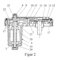
- FIG. 2 shows the cover 15 and the servomotor 6 and the gear transmission 7 the throttle valve control unit 1 according to the invention in section.
- the in the embodiment The servomotor shown is a DC motor with a pole ring 19, a Armature 20 and a collector 21, the brush elements 22 in connection stands.
- the cover 15 In the preassembled state, the cover 15 has a bearing 23 for the cover-side Bearing of the motor shaft 8 and the brush elements 22 through which the Actuator is energized on.
- the gear transmission is made in a known manner from that on the motor shaft 8 arranged pinion 9, the gear 10 and the adjusting wheel 11 together.
- the sensor unit 12 consists of wiper elements 14, which cooperate with potentiometer tracks 13 in a known manner. It should be clear that of course other sensor units, such as non-contact sensor units that act capacitive, magnetoresistive or act on the Hall principle in the present throttle valve actuating unit can be.
- the assembly of the throttle valve actuating unit according to the invention can now be carried out as follows as described.
- the potentiometer tracks 13 with the intermediate element can also be inserted into the lid be, with guide elements a precisely fitting arrangement in the lid provide.
- the intermediate element is provided by spring elements provided on the cover brought under tension and there is an electrical contact automatically to the coupling element 16 created.
Landscapes
- Engineering & Computer Science (AREA)
- Chemical & Material Sciences (AREA)
- Combustion & Propulsion (AREA)
- Mechanical Engineering (AREA)
- General Engineering & Computer Science (AREA)
- Control Of Throttle Valves Provided In The Intake System Or In The Exhaust System (AREA)
- Electrically Driven Valve-Operating Means (AREA)
- Lift Valve (AREA)
Applications Claiming Priority (2)
| Application Number | Priority Date | Filing Date | Title |
|---|---|---|---|
| DE10024426A DE10024426A1 (de) | 2000-05-19 | 2000-05-19 | Klappenstelleinheit |
| DE10024426 | 2000-05-19 |
Publications (3)
| Publication Number | Publication Date |
|---|---|
| EP1156200A2 true EP1156200A2 (fr) | 2001-11-21 |
| EP1156200A3 EP1156200A3 (fr) | 2002-11-06 |
| EP1156200B1 EP1156200B1 (fr) | 2006-03-01 |
Family
ID=7642564
Family Applications (1)
| Application Number | Title | Priority Date | Filing Date |
|---|---|---|---|
| EP01109256A Expired - Lifetime EP1156200B1 (fr) | 2000-05-19 | 2001-04-14 | Dispositif de commande d'une valve |
Country Status (4)
| Country | Link |
|---|---|
| US (1) | US6581569B2 (fr) |
| EP (1) | EP1156200B1 (fr) |
| DE (2) | DE10024426A1 (fr) |
| ES (1) | ES2258042T3 (fr) |
Cited By (1)
| Publication number | Priority date | Publication date | Assignee | Title |
|---|---|---|---|---|
| EP2202398A3 (fr) * | 2008-12-23 | 2014-02-12 | Robert Bosch GmbH | Dispositif d'actionnement |
Families Citing this family (14)
| Publication number | Priority date | Publication date | Assignee | Title |
|---|---|---|---|---|
| US6488010B2 (en) * | 2000-01-18 | 2002-12-03 | Hitachi, Ltd. | Throttle device for internal-combustion engine |
| US6691678B1 (en) * | 2000-04-05 | 2004-02-17 | Hitachi, Ltd. | Throttle assembly for internal combustion engine, and throttle sensor |
| JP3893907B2 (ja) * | 2001-06-14 | 2007-03-14 | 株式会社デンソー | 内燃機関用吸気制御装置 |
| DE10133631A1 (de) | 2001-07-11 | 2003-01-30 | Siemens Ag | Verfahren zur berührungslosen Erfassung der Position einer Drosselklappenwelle eines Drosselklappenstutzens und Drosselklappenstutzen |
| DE10137771A1 (de) * | 2001-08-02 | 2003-02-20 | Bosch Gmbh Robert | Drosselklappeneinheit mit integrierter Drosselklappe |
| JP3948016B2 (ja) * | 2002-06-27 | 2007-07-25 | 株式会社デンソー | スロットル装置 |
| JP2004132232A (ja) * | 2002-10-09 | 2004-04-30 | Aisan Ind Co Ltd | スロットル制御装置 |
| JP4055547B2 (ja) * | 2002-10-25 | 2008-03-05 | 株式会社デンソー | 電子制御式スロットル制御装置 |
| DE10341396B3 (de) | 2003-09-05 | 2004-12-16 | Pierburg Gmbh | Klappenstellvorrichtung |
| US7032885B2 (en) * | 2004-07-22 | 2006-04-25 | Automotive Components Holdings, Llc | Throttle body and method of assembly |
| US7574797B2 (en) * | 2004-07-22 | 2009-08-18 | Ford Global Technologies, Llc | Throttle body and method of assembly |
| DE102006061610B4 (de) * | 2006-12-27 | 2018-09-13 | Volkswagen Ag | Verfahren zur Verwendung eines Saugrohrs für eine Brennkraftmaschine |
| DE102013201170A1 (de) * | 2013-01-24 | 2014-07-24 | Mahle International Gmbh | Rückstelleinheit, insbesondere für eine Brennkraftmaschine |
| DE102013107111A1 (de) * | 2013-07-05 | 2015-01-08 | Pierburg Gmbh | Aktor zum Antrieb einer Ventileinheit einer Verbrennungskraftmaschine |
Family Cites Families (10)
| Publication number | Priority date | Publication date | Assignee | Title |
|---|---|---|---|---|
| CS161094B2 (fr) | 1968-10-22 | 1975-05-04 | ||
| DE69627401T3 (de) * | 1995-01-17 | 2014-01-30 | Hitachi, Ltd. | Luftströmungssteuervorrichtung |
| DE19525510B4 (de) * | 1995-07-13 | 2008-05-08 | Robert Bosch Gmbh | Drosselklappenstelleinheit |
| JPH0968403A (ja) * | 1995-08-31 | 1997-03-11 | Denso Corp | スロットルバルブ開度センサ |
| JPH10153142A (ja) * | 1996-11-21 | 1998-06-09 | Aisin Seiki Co Ltd | スロットル制御装置 |
| JP3404254B2 (ja) * | 1997-05-07 | 2003-05-06 | 株式会社日立製作所 | エンジンのスロットル装置 |
| JP2000130210A (ja) * | 1998-10-29 | 2000-05-09 | Aisin Seiki Co Ltd | スロットル制御装置 |
| DE19903490C2 (de) * | 1999-01-29 | 2001-03-22 | A B Elektronik Gmbh | Deckeldrehwinkelsensor |
| US6390062B1 (en) * | 1999-05-10 | 2002-05-21 | Hitachi, Ltd. | Throttle device of internal combustion engine |
| JP2001289610A (ja) * | 1999-11-01 | 2001-10-19 | Denso Corp | 回転角度検出装置 |
-
2000
- 2000-05-19 DE DE10024426A patent/DE10024426A1/de not_active Withdrawn
-
2001
- 2001-04-14 EP EP01109256A patent/EP1156200B1/fr not_active Expired - Lifetime
- 2001-04-14 DE DE50109028T patent/DE50109028D1/de not_active Expired - Lifetime
- 2001-04-14 ES ES01109256T patent/ES2258042T3/es not_active Expired - Lifetime
- 2001-05-16 US US09/859,108 patent/US6581569B2/en not_active Expired - Lifetime
Cited By (1)
| Publication number | Priority date | Publication date | Assignee | Title |
|---|---|---|---|---|
| EP2202398A3 (fr) * | 2008-12-23 | 2014-02-12 | Robert Bosch GmbH | Dispositif d'actionnement |
Also Published As
| Publication number | Publication date |
|---|---|
| US6581569B2 (en) | 2003-06-24 |
| EP1156200B1 (fr) | 2006-03-01 |
| US20010045203A1 (en) | 2001-11-29 |
| ES2258042T3 (es) | 2006-08-16 |
| EP1156200A3 (fr) | 2002-11-06 |
| DE10024426A1 (de) | 2001-11-22 |
| DE50109028D1 (de) | 2006-04-27 |
Similar Documents
| Publication | Publication Date | Title |
|---|---|---|
| EP1156200A2 (fr) | Dispositif de commande d'une valve | |
| DE202018006476U1 (de) | Elektromechanisches, aktives, doppelt-redundantes, zweimotoriges Stellglied zur Betätigung einer Komponente eines Fahrzeugs | |
| DE102008052846C5 (de) | Abgasklappenantrieb für ein Kraftfahrzeug sowie die Verwendung eines solchen Abgasklappenantriebes | |
| DE102014207330A1 (de) | Abgassystem für Brennkraftmaschine | |
| DE102017207929B4 (de) | Stelleinrichtung und zugehöriges Herstellungsverfahren | |
| DE10209052A1 (de) | Torsionsfederaufbau für eine elektronische Luftdrossel | |
| DE10321653B3 (de) | Stellvorrichtung für eine Verbrennungskraftmaschine | |
| EP1091112B1 (fr) | Soupape, conduit d'admission d'air et unité de recirculation de gaz d'échappement pour moteurs à combustion | |
| EP2507498B1 (fr) | Système de vanne pour moteur à combustion interne | |
| WO2015000617A1 (fr) | Actionneur permettant d'entraîner un ensemble soupape d'un moteur à combustion interne | |
| DE102008036462B4 (de) | Ventiltriebvorrichtung | |
| DE212022000093U1 (de) | Aktor | |
| DE102019128049B4 (de) | Elektrische Stelleinheit | |
| DE102006035062A1 (de) | Integriertes Antriebselement | |
| DE102013101302B4 (de) | Ventil, insbesondere Niederdruckventil, zur Steuerung einer Abgasrückführung bei einer Brennkraftmaschine | |
| EP1004754A2 (fr) | Connecteurs pour dispositif de contrôle moteur | |
| WO2005028936A1 (fr) | Dispositif de positionnement de clapet | |
| DE102004060714A1 (de) | Schaltklappeneinrichtung | |
| DE102022103040A1 (de) | Spindelantrieb-Baukastensystem sowie Spindelantrieb | |
| DE102006026446B4 (de) | Deckel für eine Stellvorrichtung mit einem Stanzgitter als Scharnier | |
| DE102009054311A1 (de) | Ventilvorrichtung für eine Verbrennungskraftmaschine | |
| DE102017103643A1 (de) | Stellvorrichtung | |
| EP2769069A1 (fr) | Dispositif d'etranglement | |
| DE19709748A1 (de) | Drosselvorrichtung für eine Brennkraftmaschine | |
| EP2388464A1 (fr) | Moteurs à combustion interne et coiffe de tête de cylindre |
Legal Events
| Date | Code | Title | Description |
|---|---|---|---|
| PUAI | Public reference made under article 153(3) epc to a published international application that has entered the european phase |
Free format text: ORIGINAL CODE: 0009012 |
|
| 17P | Request for examination filed |
Effective date: 20010414 |
|
| AK | Designated contracting states |
Kind code of ref document: A2 Designated state(s): AT BE CH CY DE DK ES FI FR GB GR IE IT LI LU MC NL PT SE TR |
|
| AX | Request for extension of the european patent |
Free format text: AL;LT;LV;MK;RO;SI |
|
| RAP1 | Party data changed (applicant data changed or rights of an application transferred) |
Owner name: PIERBURG GMBH |
|
| PUAL | Search report despatched |
Free format text: ORIGINAL CODE: 0009013 |
|
| AK | Designated contracting states |
Kind code of ref document: A3 Designated state(s): AT BE CH CY DE DK ES FI FR GB GR IE IT LI LU MC NL PT SE TR |
|
| AX | Request for extension of the european patent |
Free format text: AL;LT;LV;MK;RO;SI |
|
| AKX | Designation fees paid |
Designated state(s): DE ES FR GB IT |
|
| GRAP | Despatch of communication of intention to grant a patent |
Free format text: ORIGINAL CODE: EPIDOSNIGR1 |
|
| GRAS | Grant fee paid |
Free format text: ORIGINAL CODE: EPIDOSNIGR3 |
|
| GRAA | (expected) grant |
Free format text: ORIGINAL CODE: 0009210 |
|
| AK | Designated contracting states |
Kind code of ref document: B1 Designated state(s): DE ES FR GB IT |
|
| REG | Reference to a national code |
Ref country code: GB Ref legal event code: FG4D Free format text: NOT ENGLISH |
|
| GBT | Gb: translation of ep patent filed (gb section 77(6)(a)/1977) |
Effective date: 20060329 |
|
| REF | Corresponds to: |
Ref document number: 50109028 Country of ref document: DE Date of ref document: 20060427 Kind code of ref document: P |
|
| REG | Reference to a national code |
Ref country code: ES Ref legal event code: FG2A Ref document number: 2258042 Country of ref document: ES Kind code of ref document: T3 |
|
| ET | Fr: translation filed | ||
| PLBE | No opposition filed within time limit |
Free format text: ORIGINAL CODE: 0009261 |
|
| STAA | Information on the status of an ep patent application or granted ep patent |
Free format text: STATUS: NO OPPOSITION FILED WITHIN TIME LIMIT |
|
| 26N | No opposition filed |
Effective date: 20061204 |
|
| PGFP | Annual fee paid to national office [announced via postgrant information from national office to epo] |
Ref country code: ES Payment date: 20090424 Year of fee payment: 9 |
|
| PGFP | Annual fee paid to national office [announced via postgrant information from national office to epo] |
Ref country code: GB Payment date: 20090424 Year of fee payment: 9 |
|
| GBPC | Gb: european patent ceased through non-payment of renewal fee |
Effective date: 20100414 |
|
| PG25 | Lapsed in a contracting state [announced via postgrant information from national office to epo] |
Ref country code: GB Free format text: LAPSE BECAUSE OF NON-PAYMENT OF DUE FEES Effective date: 20100414 |
|
| REG | Reference to a national code |
Ref country code: ES Ref legal event code: FD2A Effective date: 20110714 |
|
| PG25 | Lapsed in a contracting state [announced via postgrant information from national office to epo] |
Ref country code: ES Free format text: LAPSE BECAUSE OF NON-PAYMENT OF DUE FEES Effective date: 20110704 |
|
| PG25 | Lapsed in a contracting state [announced via postgrant information from national office to epo] |
Ref country code: ES Free format text: LAPSE BECAUSE OF NON-PAYMENT OF DUE FEES Effective date: 20100415 |
|
| REG | Reference to a national code |
Ref country code: FR Ref legal event code: PLFP Year of fee payment: 16 |
|
| PGFP | Annual fee paid to national office [announced via postgrant information from national office to epo] |
Ref country code: DE Payment date: 20160421 Year of fee payment: 16 |
|
| PGFP | Annual fee paid to national office [announced via postgrant information from national office to epo] |
Ref country code: FR Payment date: 20160422 Year of fee payment: 16 Ref country code: IT Payment date: 20160422 Year of fee payment: 16 |
|
| REG | Reference to a national code |
Ref country code: DE Ref legal event code: R119 Ref document number: 50109028 Country of ref document: DE |
|
| REG | Reference to a national code |
Ref country code: FR Ref legal event code: ST Effective date: 20171229 |
|
| PG25 | Lapsed in a contracting state [announced via postgrant information from national office to epo] |
Ref country code: FR Free format text: LAPSE BECAUSE OF NON-PAYMENT OF DUE FEES Effective date: 20170502 Ref country code: DE Free format text: LAPSE BECAUSE OF NON-PAYMENT OF DUE FEES Effective date: 20171103 |
|
| PG25 | Lapsed in a contracting state [announced via postgrant information from national office to epo] |
Ref country code: IT Free format text: LAPSE BECAUSE OF NON-PAYMENT OF DUE FEES Effective date: 20170414 |