EP1156221A2 - Pompe à engrenages - Google Patents
Pompe à engrenages Download PDFInfo
- Publication number
- EP1156221A2 EP1156221A2 EP01108910A EP01108910A EP1156221A2 EP 1156221 A2 EP1156221 A2 EP 1156221A2 EP 01108910 A EP01108910 A EP 01108910A EP 01108910 A EP01108910 A EP 01108910A EP 1156221 A2 EP1156221 A2 EP 1156221A2
- Authority
- EP
- European Patent Office
- Prior art keywords
- cover
- end faces
- gear pump
- cover element
- gears
- Prior art date
- Legal status (The legal status is an assumption and is not a legal conclusion. Google has not performed a legal analysis and makes no representation as to the accuracy of the status listed.)
- Withdrawn
Links
- 229910000831 Steel Inorganic materials 0.000 claims description 6
- 239000010959 steel Substances 0.000 claims description 6
- 229910052751 metal Inorganic materials 0.000 claims description 5
- 239000002184 metal Substances 0.000 claims description 5
- 229910052782 aluminium Inorganic materials 0.000 claims description 2
- XAGFODPZIPBFFR-UHFFFAOYSA-N aluminium Chemical compound [Al] XAGFODPZIPBFFR-UHFFFAOYSA-N 0.000 claims description 2
- 230000002093 peripheral effect Effects 0.000 claims description 2
- 238000007789 sealing Methods 0.000 description 12
- 239000000446 fuel Substances 0.000 description 7
- 238000002485 combustion reaction Methods 0.000 description 2
- 238000007373 indentation Methods 0.000 description 2
- 238000002347 injection Methods 0.000 description 2
- 239000007924 injection Substances 0.000 description 2
- 230000033001 locomotion Effects 0.000 description 2
- 239000000463 material Substances 0.000 description 2
- 230000036316 preload Effects 0.000 description 2
- 238000005086 pumping Methods 0.000 description 2
- 230000015572 biosynthetic process Effects 0.000 description 1
- 230000006835 compression Effects 0.000 description 1
- 238000007906 compression Methods 0.000 description 1
- 230000008878 coupling Effects 0.000 description 1
- 238000010168 coupling process Methods 0.000 description 1
- 238000005859 coupling reaction Methods 0.000 description 1
- 230000001419 dependent effect Effects 0.000 description 1
- 238000011161 development Methods 0.000 description 1
- 230000018109 developmental process Effects 0.000 description 1
- 239000002283 diesel fuel Substances 0.000 description 1
- 238000010438 heat treatment Methods 0.000 description 1
- 239000013585 weight reducing agent Substances 0.000 description 1
Images


Classifications
-
- F—MECHANICAL ENGINEERING; LIGHTING; HEATING; WEAPONS; BLASTING
- F04—POSITIVE - DISPLACEMENT MACHINES FOR LIQUIDS; PUMPS FOR LIQUIDS OR ELASTIC FLUIDS
- F04C—ROTARY-PISTON, OR OSCILLATING-PISTON, POSITIVE-DISPLACEMENT MACHINES FOR LIQUIDS; ROTARY-PISTON, OR OSCILLATING-PISTON, POSITIVE-DISPLACEMENT PUMPS
- F04C15/00—Component parts, details or accessories of machines, pumps or pumping installations, not provided for in groups F04C2/00 - F04C14/00
- F04C15/0003—Sealing arrangements in rotary-piston machines or pumps
- F04C15/0023—Axial sealings for working fluid
- F04C15/0026—Elements specially adapted for sealing of the lateral faces of intermeshing-engagement type machines or pumps, e.g. gear machines or pumps
Definitions
- the invention relates to a gear pump according to the Genus of claim 1.
- Such a gear pump is by DE 196 38 332 A1 known.
- This gear pump has a housing in which between a housing part and a cover part Pump chamber is formed. There is a rotating one in the pumping chamber driven pair of each other on their outer circumference intermeshing gears arranged.
- the gears promote Pumped medium from a connected to a storage tank Suction space along between the circumference of the gears and Circumferential walls of the pumping chamber formed in a pressure room.
- the pump chamber is through the cover part limited, which is opposite the end faces of the gears and as close as possible to the end faces of the gears to ensure a secure sealing of the delivery channels and thus a good efficiency of the gear pump to reach.
- the gear pump according to the invention with the features according to claim 1 has the advantage that the Cover element a secure seal of the delivery channels is achieved and a required game towards the Axis of rotation of the gears against the bias of the Can adjust cover element.
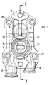
- FIG. 1 shows a gear pump in a view according to arrow I in Figure 2
- Figure 2 the Gear pump in a cross section along line II-II in Figure 1 according to a first embodiment
- Figure 2a a cover element according to a first embodiment
- Figure 2b the cover element according to a second embodiment
- Figure 3 the gear pump in cross section according to a second Embodiment
- Figure 4 the gear pump in Cross section according to one compared to the third Embodiment modified design
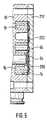
- Figure 5 the Gear pump in cross section according to a third Embodiment.
- a gear pump shown in Figures 1 to 5 is in a delivery line, not shown, from one Storage tank to a high pressure fuel pump or Fuel injection pump of an internal combustion engine Motor vehicle arranged.
- the internal combustion engine is one compression ignition engine and the fuel that is conveyed by the gear pump Diesel fuel.
- the gear pump has one multi-part housing on, which consists of a housing part 10 and there is a cover part 12. Between the housing part 10 and the cover part 12, a pump chamber 14 is formed, in which a pair intermeshing on their outer circumference Gears 16, 18 is arranged.
- the housing part 10 faces Formation of the pump chamber 14 two depressions 20, 22 on, of the reason for which a journal 24, 26 protrudes.
- the Bearing journals 24, 26 are in one piece with the housing part 10 trained and run at least approximately parallel to each other.
- the journals 24, 26 can be used for Weight reduction of the housing part 10 at least partially be hollow.
- the gear wheel 16 has a bore 17 on which it is rotatably supported on the journal 24 is.
- the gear 18 has a bore 19 through which it is rotatably supported on the journal 26.
- the lid part 12 is firmly connected to the housing part 10, for example by means of several screws 28.
- the housing part 10 and the Cover part 12 are preferably made of light metal, especially aluminum.
- the gears 16, 18 exist preferably made of steel, in particular sintered steel.
- the gear pump has a drive shaft 30 which is rotatably supported in the housing part 10.
- the drive shaft 30 is at least approximately coaxial with the journal 24 arranged, the housing part 10 having a bore 32 has, which continues in the journal 24 and by the the end of the drive shaft 30 passes through.
- Between the Bore 32 and the drive shaft 30 is a shaft seal 34 installed to seal the housing part 10.
- the Drive shaft 30 is coupled to gear 16, for example, between the front of the Bearing pin 24 and the cover part 12 arranged Coupling member 36.
- the gear 16 is in operation of the Gear pump rotating over the drive shaft 30 driven and transmits this rotary motion via a Front toothing on the also with a front toothing provided, meshing with the gear 16 on its outer circumference Gear 18.
- the gears 16, 18 share the pump chamber 14 through their meshing in two sections, one of which a first section an intake chamber 40 and a second Partial area form a pressure chamber 42.
- the suction space 40 is with one each between the tooth grooves on the Circumferential surfaces of the gears 16, 18 and the upper and lower peripheral wall of the pump chamber 14 formed delivery channel 44 connected to the pressure chamber 42.
- the suction space 40 and the Pressure chamber 42 each have a connection opening in the Wall of the housing part 10 or the cover part 12 on, over the suction chamber 40 with a not shown Intake line from the storage tank and the pressure chamber 42 via a also not shown delivery line with the suction chamber the high pressure fuel pump or the Fuel injection pump is connected.
- the connection opening in the suction space 40 forms an inlet opening 46 and Connection opening in the pressure chamber 42 forms one Outlet opening 48.
- the gear pump according to a first Embodiment shown.
- the cover part 12 has in its inside of the housing part 10 facing one Well 50 on at least in one area is formed in which the end faces of the gear wheels 16, 18 lie opposite the cover part 12.
- the cross section of the Indentation 50 is at least as large as the cross section the end faces of the gears 16, 18.
- a plate-shaped Cover element 52 fixed to the pump chamber 14 surrounding end face of the housing part 10 and to the End faces of the gears 16,18.
- the cover element 52 is in an outside of the end faces of the gears 16,18 lying edge area between the end faces of the Housing part 10 and the cover part 12 clamped and in In the area of the depression 50, the cover element 52 lies below Preload on the end faces of the gears 16, 18 and is arranged at a distance from the recess 50.
- the Cover element 52 is thus opposite the gears 16, 18 arranged fixed.
- an elastic sealing element in the form a sealing ring 51 is arranged between the housing part 10 and the Cover element 52 arranged.
- the cover element 52 can to the end faces of the gears 16,18 have a curvature in the Sectional view of the gear pump according to Figure 2 but is not recognizable. In Figures 2a and 2b therefore the cover element 52 in addition not installed State shown, in order to illustrate its curvature make, which is shown very exaggerated.
- the Cover element 52 has according to one shown in Figure 2a Execution of a convex curvature. In one in Figure 2b shown embodiment has the cover member 52 Achieving the curvature towards the front of the gears 16,18 offset area.
- the cover member 52 is at least in his on the end faces of the gears 16, 18 adjacent area formed resiliently deformable and its pretension is due to the curvature and the clamping of the cover member 52 between the housing part 10 and the Cover part 12 generated.
- the cover element 52 can for example made of metal, in particular steel, or Plastic, the thickness of the cover 52nd is chosen accordingly to the required elasticity of the cover element 52 in its on the end faces of the To reach gears 16,18 adjacent area.
- the Cover element 52 has at least one opening 54 through the depression 52 formed by the cover element 52 is closed, is connected to the suction chamber 40. Between the end face of the housing part 10 and the Cover element 52, a sealing ring 56 is clamped.
- the resilient design of the cover element 52 can be a Required axial play of the gears 16, 18 to the cover part 12 adjust by the cover 52 in the Well 50 evades.
- By connecting the recess 50 through the opening 54 with the suction chamber 40 can Springing of the cover element 52 into the depression 50 displaced air or fuel into the intake space 40 escape.
- the gears 16, 18 and the housing part 10 heat up and the cover part 12, which is due to the different materials from which these parts exist, expand to different extents.
- the gear pump according to a second Embodiment shown in which the basic Structure is the same as in the first embodiment, however, the cover part 112 and the cover element 152 are modified.
- the cover part 112 has on it End faces of the gears 16, 18 facing the inside Indentation 150, which is slightly larger in cross section than the cross-sectional areas of the end faces of the gear wheels 16, 18.
- the cover element 152 is in turn plate-shaped and in its outside the end faces of the gears 16, 18 lying edge area between the housing part 10 and the Cover part 112 set.
- the cover member 152 is again fixed relative to the gears 16, 18 arranged.
- the cover element 152 is supported on the cover part 112, especially at the bottom of its depression 150, over an elastic sealing element 60.
- the sealing element 60 is designed as a sealing ring that over the outer edge of the Cover element 152 extends and on which this in the direction the axes of rotation of the gears 16,18.
- the Cover element 152 can be resiliently deformable or relatively rigid be formed and made of metal or plastic.
- the cover element 152 can face the end faces of the gears 16,18 facing a convex curvature or be at least approximately flat.
- On The required axial play of the gears 16, 18 can change by an axial movement of the cover element 152 adjust by pressing the sealing ring 60 together. If the gear pump is not in operation, then the cover element 152 under prestress by the Sealing ring 60 is generated on the end faces of the gears 16.18.
- the function of the cover element 152 for Allowing a necessary axial play is the same as in the first embodiment, by this in the Well 150 can dodge.
- the cover element 152 has the opening 54 for connecting the recess 150 with the Intake space 40.
- the gear pump according to a third Embodiment shown.
- the basic structure the gear pump is again the same as for the Embodiments explained above.
- the lid part 212 of the gear pump is with the housing part 10 connected and has a recess 250 which in its Cross-sectional shape at least approximately the same as that Cross-sectional shape of the pump chamber 14 is formed and at least approximately congruent with the pump chamber 14 is arranged.
- a cover element 252 arranged, its cross-sectional shape at least approximately is equal to that of the recess 250.
- the cover member 252 is in the recess 250 non-rotatable and thus in relation to the Gears 16,18 arranged stationary.
- the cover element 252 can be rigid be trained and need not be resiliently deformable and can be made of metal or plastic.
- the springy Pressing element 64 can be used, for example, as a corrugated spring be formed, which can be made of steel and which at least approximately over the entire area of the Cover element 252 extends so that a uniform pressing force of the cover element 252 on the End faces of the gears 16.18 results.
- the cover element 252 has the opening 54 for connecting the recess 250 with the suction chamber 40.
- the cover member 252 is due to the Resilient pressing element 64 causes the End faces of the gear wheels 16, 18.
- the cover element 252 may have a required axial play of the gears 16, 18 by the cover element 252 against the bias of the resilient pressing element 64 in the recess 250 evades.
Landscapes
- Engineering & Computer Science (AREA)
- Mechanical Engineering (AREA)
- General Engineering & Computer Science (AREA)
- Rotary Pumps (AREA)
- Details And Applications Of Rotary Liquid Pumps (AREA)
Applications Claiming Priority (2)
| Application Number | Priority Date | Filing Date | Title |
|---|---|---|---|
| DE10024884 | 2000-05-19 | ||
| DE10024884A DE10024884A1 (de) | 2000-05-19 | 2000-05-19 | Zahnradförderpumpe |
Publications (2)
| Publication Number | Publication Date |
|---|---|
| EP1156221A2 true EP1156221A2 (fr) | 2001-11-21 |
| EP1156221A3 EP1156221A3 (fr) | 2002-11-06 |
Family
ID=7642837
Family Applications (1)
| Application Number | Title | Priority Date | Filing Date |
|---|---|---|---|
| EP01108910A Withdrawn EP1156221A3 (fr) | 2000-05-19 | 2001-04-10 | Pompe à engrenages |
Country Status (3)
| Country | Link |
|---|---|
| US (1) | US6527529B2 (fr) |
| EP (1) | EP1156221A3 (fr) |
| DE (1) | DE10024884A1 (fr) |
Cited By (7)
| Publication number | Priority date | Publication date | Assignee | Title |
|---|---|---|---|---|
| FR2974862A1 (fr) * | 2011-05-06 | 2012-11-09 | Bosch Gmbh Robert | Pompe a engrenage |
| WO2016096755A1 (fr) * | 2014-12-17 | 2016-06-23 | Brose Fahrzeugteile GmbH & Co. Kommanditgesellschaft, Würzburg | Pompe à huile électrique, notamment pour véhicule à moteur |
| EP3141697A3 (fr) * | 2015-08-21 | 2017-05-31 | Bernd Niethammer | Pompe excentrique, en particulier pompe d'alimentation pour solutions aqueuses d'uree et dispositif d'alimentation comprenant une pompe excentrique |
| WO2018103911A1 (fr) * | 2016-12-08 | 2018-06-14 | Robert Bosch Gmbh | Pompe à engrenage |
| IT201700067423A1 (it) * | 2017-06-16 | 2018-12-16 | Gkn Sinter Metals Ag | Disposizione di pompa e procedimento per la produzione di una disposizione di pompa. |
| IT201700067438A1 (it) * | 2017-06-16 | 2018-12-16 | Gkn Sinter Metals Ag | Disposizione di pompa. |
| IT201700067446A1 (it) * | 2017-06-16 | 2018-12-16 | Gkn Sinter Metals Ag | Disposizione di pompa e procedimento per la produzione di una disposizione di pompa. |
Families Citing this family (4)
| Publication number | Priority date | Publication date | Assignee | Title |
|---|---|---|---|---|
| US7515785B2 (en) * | 2003-01-15 | 2009-04-07 | Fujikura Ltd. | Dispersion compensation element, optical crystal, dispersion compensation system, dispersion compensation method |
| JP2005163676A (ja) * | 2003-12-03 | 2005-06-23 | Seiko Epson Corp | ギヤポンプ、及び液体噴射装置 |
| DE102018202150B3 (de) | 2018-02-12 | 2019-03-21 | Magna Powertrain Bad Homburg GmbH | Gerotorpumpe |
| DE102023122187A1 (de) * | 2023-08-18 | 2025-02-20 | Thomas Magnete Gmbh | Gerotorpumpe und Motor-Pumpen-Einheit |
Citations (1)
| Publication number | Priority date | Publication date | Assignee | Title |
|---|---|---|---|---|
| DE19638332A1 (de) | 1996-09-19 | 1998-03-26 | Bosch Gmbh Robert | Förderpumpe |
Family Cites Families (22)
| Publication number | Priority date | Publication date | Assignee | Title |
|---|---|---|---|---|
| US1694805A (en) * | 1927-04-01 | 1928-12-11 | Wiltse Appliance Company | Fuel-supply system for internal-combustion engines |
| US2345975A (en) * | 1938-12-24 | 1944-04-04 | Vickers Inc | Power transmission pump or motor |
| US2477797A (en) * | 1945-08-06 | 1949-08-02 | Nellie M Gottschalt | Gear pump with wear compensating means |
| US2622534A (en) * | 1946-02-18 | 1952-12-23 | James P Johnson | Gear pump |
| US2702509A (en) * | 1951-04-06 | 1955-02-22 | Air Equipment | Rotary pump |
| US3019737A (en) * | 1960-02-12 | 1962-02-06 | Thompson Ramo Wooldridge Inc | Leaf spring seal for pumps |
| US3068804A (en) * | 1960-03-21 | 1962-12-18 | Thompson Ramo Wooldridge Inc | Pressure loaded pump seal |
| US2996997A (en) * | 1960-05-19 | 1961-08-22 | Borg Warner | Reversible hydraulic pump or motor |
| US3153371A (en) * | 1961-11-20 | 1964-10-20 | Cessna Aircraft Co | Delayed pressure loading for gear motors |
| DE1653837A1 (de) * | 1968-03-14 | 1975-03-20 | Otto Eckerle | Hochdruckpumpe, insbesondere hochdruck-zahnradpumpe |
| GB1329969A (en) * | 1969-12-12 | 1973-09-12 | Bradley Ltd G & E | Gear pumps |
| US3695791A (en) * | 1970-09-18 | 1972-10-03 | Emerson Electric Co | Variable sealed hydraulic pump or motor |
| GB1411750A (en) * | 1971-11-24 | 1975-10-29 | Smiths Industries Ltd | Gear pumps |
| JPS4946206A (fr) * | 1972-09-06 | 1974-05-02 | ||
| FR2212861A5 (fr) * | 1972-12-28 | 1974-07-26 | Retel | |
| JPS5514783Y2 (fr) * | 1975-05-01 | 1980-04-04 | ||
| JPS6062682A (ja) * | 1984-03-05 | 1985-04-10 | Hitachi Maxell Ltd | ギヤポンプ |
| DE4021500C3 (de) * | 1990-07-05 | 1998-10-22 | Mannesmann Vdo Ag | Förderaggregat, insbesondere zum Fördern von Kraftstoff |
| FR2681647B1 (fr) * | 1991-09-24 | 1995-05-12 | Hydroperfect Int | Machine hydraulique du type a engrenage a corps flottant. |
| JPH0893657A (ja) * | 1994-09-29 | 1996-04-09 | Aiwa Co Ltd | 歯車ポンプ |
| JPH1030578A (ja) * | 1996-07-12 | 1998-02-03 | Matsushita Electric Ind Co Ltd | ギヤポンプ |
| DE19802443C1 (de) * | 1998-01-23 | 1999-05-12 | Luk Fahrzeug Hydraulik | Pumpe |
-
2000
- 2000-05-19 DE DE10024884A patent/DE10024884A1/de not_active Ceased
-
2001
- 2001-04-10 EP EP01108910A patent/EP1156221A3/fr not_active Withdrawn
- 2001-05-18 US US09/859,474 patent/US6527529B2/en not_active Expired - Fee Related
Patent Citations (1)
| Publication number | Priority date | Publication date | Assignee | Title |
|---|---|---|---|---|
| DE19638332A1 (de) | 1996-09-19 | 1998-03-26 | Bosch Gmbh Robert | Förderpumpe |
Cited By (13)
| Publication number | Priority date | Publication date | Assignee | Title |
|---|---|---|---|---|
| FR2974862A1 (fr) * | 2011-05-06 | 2012-11-09 | Bosch Gmbh Robert | Pompe a engrenage |
| US10533550B2 (en) | 2014-12-17 | 2020-01-14 | Brose Fahrzeugteile Gmbh & Co. Kg, Wuerzburg | Electric oil pump, in particular for a motor vehicle |
| WO2016096755A1 (fr) * | 2014-12-17 | 2016-06-23 | Brose Fahrzeugteile GmbH & Co. Kommanditgesellschaft, Würzburg | Pompe à huile électrique, notamment pour véhicule à moteur |
| EP3141697A3 (fr) * | 2015-08-21 | 2017-05-31 | Bernd Niethammer | Pompe excentrique, en particulier pompe d'alimentation pour solutions aqueuses d'uree et dispositif d'alimentation comprenant une pompe excentrique |
| WO2018103911A1 (fr) * | 2016-12-08 | 2018-06-14 | Robert Bosch Gmbh | Pompe à engrenage |
| IT201700067438A1 (it) * | 2017-06-16 | 2018-12-16 | Gkn Sinter Metals Ag | Disposizione di pompa. |
| IT201700067446A1 (it) * | 2017-06-16 | 2018-12-16 | Gkn Sinter Metals Ag | Disposizione di pompa e procedimento per la produzione di una disposizione di pompa. |
| WO2018229244A1 (fr) * | 2017-06-16 | 2018-12-20 | Gkn Sinter Metals Ag | Dispositif de pompe |
| WO2018229243A1 (fr) * | 2017-06-16 | 2018-12-20 | Gkn Sinter Metals Ag | Agencement de pompe et procédé pour la fabrication d'un agencement de pompe |
| IT201700067423A1 (it) * | 2017-06-16 | 2018-12-16 | Gkn Sinter Metals Ag | Disposizione di pompa e procedimento per la produzione di una disposizione di pompa. |
| CN110998064A (zh) * | 2017-06-16 | 2020-04-10 | 吉凯恩粉末冶金股份公司 | 泵组件 |
| CN111032999A (zh) * | 2017-06-16 | 2020-04-17 | 吉凯恩粉末冶金股份公司 | 泵组件和用于生产泵组件的方法 |
| US11662011B2 (en) | 2017-06-16 | 2023-05-30 | Gkn Sinter Metals Ag | Pump assembly and method for producing a pump assembly |
Also Published As
| Publication number | Publication date |
|---|---|
| DE10024884A1 (de) | 2001-11-22 |
| US20020021978A1 (en) | 2002-02-21 |
| US6527529B2 (en) | 2003-03-04 |
| EP1156221A3 (fr) | 2002-11-06 |
Similar Documents
| Publication | Publication Date | Title |
|---|---|---|
| DE3927589C2 (de) | Dichtungseinheit | |
| DE69727171T2 (de) | Motorangetriebene Hydraulikpumpe und in ihr angewendete Kupplung | |
| EP0536159A1 (fr) | Organe pour l'alimentation du moteur a combustion interne d'un vehicule a moteur avec du carburant provenant d'un reservoir. | |
| EP1156221A2 (fr) | Pompe à engrenages | |
| DE1553276C3 (de) | Dichtungsanordnung in einer Zahnradpumpe | |
| DE102018133681A1 (de) | Rotationspumpe mit axialer Kompensation, Auslassdichtung für eine Pumpe sowie vormontierte Pumpeneinheit | |
| DE19712872A1 (de) | Pumpe, insbesonder Hochdruckpumpe für eine Kraftstoffeinspritzvorrichtung eines Verbrennungsmotors | |
| DE10337847A1 (de) | Pumpenanordnung mit einer Hochdruckpumpe und einer dieser vorgeschalteten Niederdruckpumpe für eine Kraftstoffeinspritzeinrichtung einer Brennkraftmaschine | |
| EP3903006A1 (fr) | Pompe rotative à compensation axiale, garniture d'étanchéité de sortie pour une pompe et ensemble pompe prémonté | |
| EP1209359A2 (fr) | Pompe à engrenages | |
| EP0831232B1 (fr) | Pompe à engrenages | |
| DE2917909A1 (de) | Stirndichtung eines umlaufkolbenverbrennungsmotors | |
| DE3048984A1 (de) | Rotationslaufradpumpe oder -motor | |
| DE102018133680A1 (de) | Rotationspumpe mit axialer Kompensation, Auslassdichtung für eine Pumpe sowie vormontierte Pumpeneinheit | |
| WO2002077460A1 (fr) | Pompe d'acheminement a roues dentees | |
| DE10058794B4 (de) | Heizgerät mit einer Dichtung zum Trennen von Brennluft, Abgas und Umgebungsluft | |
| DE3303856C2 (de) | Rotationszellenpumpe | |
| WO1995029324A1 (fr) | Systeme de frein moteur pour moteur a combustion interne multicylindre | |
| EP2252795A2 (fr) | Pompe à carburant | |
| DE3445686A1 (de) | Hydraulikdruckstroemungsmitteldichtung | |
| DE102016213696B4 (de) | Zahnradfluidmaschine | |
| DE3727697A1 (de) | Rollkolbenverdichter | |
| DE10337849A1 (de) | Flüssigkeitspumpe | |
| DE19840314C1 (de) | Dichtungselement | |
| EP1373734A1 (fr) | Pompe d'acheminement a roues dentees |
Legal Events
| Date | Code | Title | Description |
|---|---|---|---|
| PUAI | Public reference made under article 153(3) epc to a published international application that has entered the european phase |
Free format text: ORIGINAL CODE: 0009012 |
|
| AK | Designated contracting states |
Kind code of ref document: A2 Designated state(s): AT BE CH CY DE DK ES FI FR GB GR IE IT LI LU MC NL PT SE TR |
|
| AX | Request for extension of the european patent |
Free format text: AL;LT;LV;MK;RO;SI |
|
| PUAL | Search report despatched |
Free format text: ORIGINAL CODE: 0009013 |
|
| AK | Designated contracting states |
Kind code of ref document: A3 Designated state(s): AT BE CH CY DE DK ES FI FR GB GR IE IT LI LU MC NL PT SE TR |
|
| AX | Request for extension of the european patent |
Free format text: AL;LT;LV;MK;RO;SI |
|
| AKX | Designation fees paid | ||
| REG | Reference to a national code |
Ref country code: DE Ref legal event code: 8566 |
|
| STAA | Information on the status of an ep patent application or granted ep patent |
Free format text: STATUS: THE APPLICATION IS DEEMED TO BE WITHDRAWN |
|
| 18D | Application deemed to be withdrawn |
Effective date: 20030507 |