EP1157774A2 - Leistungsversorgungsvorrichtung für Widerstandsschweissgerät - Google Patents
Leistungsversorgungsvorrichtung für Widerstandsschweissgerät Download PDFInfo
- Publication number
- EP1157774A2 EP1157774A2 EP01304514A EP01304514A EP1157774A2 EP 1157774 A2 EP1157774 A2 EP 1157774A2 EP 01304514 A EP01304514 A EP 01304514A EP 01304514 A EP01304514 A EP 01304514A EP 1157774 A2 EP1157774 A2 EP 1157774A2
- Authority
- EP
- European Patent Office
- Prior art keywords
- current
- capacitor
- voltage
- welding
- power supply
- Prior art date
- Legal status (The legal status is an assumption and is not a legal conclusion. Google has not performed a legal analysis and makes no representation as to the accuracy of the status listed.)
- Withdrawn
Links
Images

Classifications
-
- B—PERFORMING OPERATIONS; TRANSPORTING
- B23—MACHINE TOOLS; METAL-WORKING NOT OTHERWISE PROVIDED FOR
- B23K—SOLDERING OR UNSOLDERING; WELDING; CLADDING OR PLATING BY SOLDERING OR WELDING; CUTTING BY APPLYING HEAT LOCALLY, e.g. FLAME CUTTING; WORKING BY LASER BEAM
- B23K11/00—Resistance welding; Severing by resistance heating
- B23K11/24—Electric supply or control circuits therefor
- B23K11/25—Monitoring devices
- B23K11/252—Monitoring devices using digital means
- B23K11/257—Monitoring devices using digital means the measured parameter being an electrical current
Definitions
- the present invention relates generally to a power supply apparatus for resistance welding, and more particularly, to a power supply apparatus having a capacitor for temporarily storing electric power as welding energy previous to feeding via a switching element to workpieces to be welded together.
- Fig. 4 depicts a circuit configuration of such a conventional resistance welding power supply apparatus.
- a single-phase AC power supply voltage E 0 of a commercial frequency is input from an AC power supply line 100 via a transformer 102 to a rectifying circuit 104 so that a capacitor 106 is charged with a DC voltage output from the rectifying circuit 104.
- a transistor 108 acting as a switching element is closed to allow a charged energy in the capacitor 106 to be discharged to a circuit associated with welding electrodes 110 and 112 so that workpieces (W 1 and W 2 ) are supplied with a welding current i w .
- this power supply apparatus comprises current measurement means not shown which measure the welding current i w and control means not shown which provide, e.g., a PWM (pulse-width modulation) control of the switching transistor 108 so as to allow a welding current measured value to coincide with a welding current set value.
- PWM pulse-width modulation
- the capacitor 106 has had a fixed charging voltage.
- the charging voltage of the capacitor 106 has normally been set to near a possible maximum charging voltage of that apparatus so as to ensure as rapid a rise of the welding current i w as possible and ensure as large a current value as possible.
- a small welding current i w flows, however, the rate of the current ripple tended to increase, making it difficult to obtain a set current value and an expected weld quality. That is, as depicted in Fig. 5 by way of example, although substantially a constant rapid rise is obtained irrespective of the magnitude of the welding current i w , there appears substantially an unvarying large current ripple. For this reason, a small current not more than 500 amperes may often cause an intermittent supply of current substantially including only the current ripple, which renders it difficult to obtain a set current value as desired. It is to be noted in Fig. 5 that the current ripple period corresponds to the switching (ON-OFF) period of the switching transistor 108.
- the present invention was conceived in view of the above problems involved in the prior art. It is therefore an object of the present invention to provide a resistance welding power supply apparatus capable of arbitrarily variably adjusting welding current rise characteristics or current ripple characteristics.
- Another object of the present invention is to provide a resistance welding power supply apparatus capable of suppressing the influence of the current ripple irrespective of the magnitude of the welding current, to thereby ensure an acquisition of a set welding current.
- a further object of the present invention is to provide a resistance welding power supply apparatus capable of automatic adjustment of the current rise characteristics or current ripple characteristics in conjunction with the setting of a current value of the welding current.
- a resistance welding power supply apparatus for resistance welding workpieces, the apparatus having a pair of welding electrodes across which a welding current flows, the pair of welding electrodes adapted to come into pressure contact with the workpieces, the resistance welding power supply apparatus comprising a capacitor having first and second electrodes electrically connected to each electrode of the pair of welding electrodes, respectively, the capacitor storing resistance welding electric energy in the form of electric charges between the first and second electrodes; current switching means electrically connected between the capacitor and one electrode of the pair of welding electrodes; current control means arranged to provide a switching control of the current switching means to control a welding current during the supply of resistance welding current; and capacitor voltage control means arranged to control a voltage across the pair of electrodes of the capacitor to have a desired voltage value capable of being variably set.
- the capacitor discharges within a current-supplying circuit including the capacitor, the welding electrodes and workpieces to be welded together, allowing a flow of a welding current.
- the welding current undergoes a current ripple resulting from switching operations of the current switching means.
- the current ripple is proportional to the capacitor voltage.
- the welding current rise speed is also proportional to the capacitor voltage.
- the capacitor voltage control means control the voltage across the two electrodes of the capacitor to have a desired voltage value capable of being variably set whereby it is possible to arbitrarily variably adjust the welding current rise characteristics or current ripple characteristics.
- the capacitor voltage is lowered so that a desired current value can be obtained with a small current ripple.
- the resistance welding power supply apparatus of the present invention further comprises current setting means arranged to set a desired welding current and current measurement means arranged to measure a welding current fed to the workpieces; the current control means providing a switching control of the current switching means so as to allow a current measured value acquired from the current measurement means to conform to a welding current set value fed by the current setting means.
- the current control means may provide a pulse-width modulation switching control of the current switching means, or alternatively, the current control means may hold the current switching means in ON-state in a continuous manner during the supply of resistance welding current.
- the capacitor voltage control means may include capacitor voltage setting means which set a desired capacitor voltage; voltage measurement means which measure a voltage across the first and second electrodes of the capacitor; a rectifying circuit which rectifies an AC power supply voltage of a commercial frequency to output a DC voltage; charging switching means electrically connected between an output terminal of the rectifying circuit and the capacitor; and charging control means which, for charging the capacitor, provide a switching control of the charging switching means so as to allow a voltage measured value acquired from the voltage measurement means to conform to a capacitor voltage set value fed from the capacitor voltage setting means.
- the capacitor voltage control means may include current standard value selection means which select one of a plurality of preset standard values of a welding current; capacitor voltage setting means which set a capacitor voltage corresponding to a welding current standard value selected by the current standard value selection means; voltage measurement means which measure a voltage across the first and second electrodes of the capacitor; a rectifying circuit which rectifies an AC power supply voltage of a commercial frequency to output a DC voltage; charging switching means electrically connected between an output terminal of the rectifying circuit and the capacitor; and charging control means which provide a switching control of the charging switching means so as to allow a voltage measured value acquired from the voltage measurement means to conform to a capacitor voltage set value fed from the capacitor voltage setting means.
- the capacitor voltage control means may further include a discharge circuit having a discharge resistor and switching means connected in series and in parallel with the first and second electrodes of the capacitor.
- Figs. 1 to 3 illustrate a presently preferred embodiment thereof in a non-limitative manner.
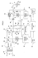
- Fig. 1 depicts a circuit configuration of a transistor resistance welding power supply apparatus in accordance with the embodiment of the present invention.
- the power supply apparatus comprises a capacitor 12 for supplying a resistance welding energy (electric power) to a welding unit 10.
- the welding unit 10 includes a pair of welding electrodes 14 and 16.
- the welding electrodes 14 and 16 are physically connected to a pressure unit not shown so that upon the resistance welding the welding electrodes 14 and 16 can come into pressure contact with workpieces W 1 and W 2 from opposed sides thereof by the action of a weld force from the pressure unit.
- the capacitor 12 is comprised of a single or a plurality of low-voltage large-capacity capacitors which are connected in parallel.
- the capacitor 12 has a positive electrode 12a that is electrically connected via switching means 18 for supplying welding current to the welding electrode 14 on one hand and a negative electrode 12b that is electrically connected to the welding electrode 16 on the other.
- the switching means 18 consist of a single or a plurality of switching transistors, e.g., FETs (field effect transistors) which are connected in parallel.
- the switching means 18 are arranged such that during the supply of welding current the switching means 18 are switching controlled via a drive circuit 22 by a current control unit 20.
- the capacitor 12 discharges in a current-supplying circuit 27 that includes the capacitor 12, the switching transistor 18, the welding electrodes 14, 16 and workpieces W1, W2, causing a momentary increase of a welding current I w .
- the rate of increase of the current is inversely proportional to the impedance of the current-supplying circuit 27 and is proportional to the voltage at the capacitor 12.
- the current control unit 20 is so arranged as to allow the welding current I w to be controlled to a desired set value or waveform under the PWM constant current control for example.
- a current sensor 24 in the form of, e.g., a toroidal coil is fitted to the current-supplying circuit 27 at an appropriate point (conductor) thereof so that based on an output signal (current detection signal) from the current sensor 24 a current measuring circuit 26 figures out a measured value, e.g., an effective value of the welding current I w and applies a thus obtained current measured value SI w to the current control unit 20.
- the current control unit 20 accepts a set value or data IWD on a set waveform of the welding current I w from a main control unit 28.
- a charging circuit 30 for charging the capacitor 12 includes a transformer 32, a rectifying circuit 34, a switching transistor (switching means) 36, an inductance coil 38 and a freewheeling diode 40.
- the transformer 32 has a primary coil that is connected to AC power lines 42 for distributing a single-phase AC power supply voltage E 0 of a commercial frequency and has a secondary coil that is connected to a pair of input terminals of the rectifying circuit 34.
- the rectifying circuit 34 is comprised of a single-phase full-wave rectifying circuit consisting of, e.g., four diodes not shown which are bridge-connected to each other.
- the rectifying circuit 34 serves to full-wave rectify an AC power supply voltage E 1 acquired at the secondary side of the transformer 32, to output a DC voltage.
- a positive output terminal 34a is connected via the switching transistor (e.g., FET) 36 to one end of the inductance coil 38, whilst a negative output terminal 34b is connected to the ground potential (grounded) and to the other end of the inductance coil 38 and to the positive electrode 12a of the capacitor 12.
- the switching transistor 36 turns on or allows conduction, a direct current I c flows through a circuit 44 that includes the positive output terminal 34a of the rectifying circuit 34, the switching transistor 36, the inductance coil 38 and the negative output terminal 34b of the rectifying circuit 34.
- a smoothing capacitor 46 is connected between the output terminals 34a and 34b of the rectifying circuit 34.
- the diode 40 has an anode terminal that is connected to the negative electrode 12b of the capacitor 12 and a cathode terminal that is connected to one end of the inductance coil 38.
- a current I d from the inductance coil 38 flows in the forward direction of the diode 40 within a closed circuit 48 including the inductance coil 38, the capacitor 12 and the diode 40 such that the capacitor 12 is charged with the freewheeling current I d .
- the switching transistor 36 While the switching transistor 36 is on, an electromagnetic energy is stored in the inductance coil 38 by the action of the current I c flowing through the output circuit 44 of the rectifying circuit 34, whereas once the switching element 36 is turned off from ON-state, the electromagnetic energy in the inductance coil 38 is transformed into an electrostatic energy (electric charge) of the capacitor 12 through the current I d flowing within the freewheeling circuit 48.
- the switching transistor 36 is arranged to be controlled via a drive circuit 52 by a charging control unit 50 during the supply of charging current.
- the charging control unit 50 executes a charging control in response to a control signal from the main control unit 28 or to an output signal CP of a comparator 54, to provide e.g., PWM constant-current control directly of the current I c within the rectifier output circuit 44 and indirectly of the current I d within the freewheeling circuit 48.
- a current sensor not shown may be fitted to the freewheeling circuit 48 or to the rectifier output circuit 44, with a current measuring circuit not shown provided to determine a measured value of the charging current I d or I c on the basis of the output signal of this current sensor.
- One input terminal of the comparator 54 accepts a voltage, i.e., a negative charging voltage - V g at the negative electrode 12b of the capacitor 12 whereas the other input terminal of the comparator 54 accepts a negative set voltage - V s which is capable of being variably set from the main control unit 28.
- the comparator 54 allows the output signal CP to go high when the charging voltage V g (absolute value) of the capacitor 12 is higher than the set voltage V s (absolute value) whereas it allows the out signal CP to go low when opposite (V g ⁇ V s ).
- the charging control unit 50 receives the output signal CP of the comparator 54 as a charging voltage monitor signal and, when the signal CP is low (V g ⁇ V s ), allows the charging unit 30 to be conductive, i.e., provides a PWM switching control of the switching transistor 36 to charge the capacitor 12.
- a discharge circuit 60 in the form of a series circuit including a resistor 56 and a transistor 58.
- the charging control unit 50 turns the transistor 58 on in response to a control signal from the main control unit 28 to cause the discharge circuit 60 to conduct to thereby relieve (discharge) the capacitor 12 of electric charges stored therein.
- the charging control unit 50 may have the discharge circuit 60 conductive while simultaneously monitoring the output signal CP of the comparator 54 (till the inversion of the signal CP from high to low), to thereby lower the capacitor charging voltage V g to the altered set voltage V s .
- the main control unit 28 includes microcomputer and various interface circuits acting as its peripheral circuits.
- the main control unit 28 feeds predetermined control signals or set values to the current control unit 20, the charging control unit 50 and the comparator 54 as described above and is further associated with an input unit 62, a display unit 64, etc.
- the input unit 62 and the display unit 64 may be comprised of a keyboard or input keys and a display, respectively, which are fitted to a console panel not shown.
- the user can operate the keys of the input unit 62 while viewing a setting screen appearing on the display unit 64, to thereby set desired values for various set items or conditions.
- the thus set data are stored in a memory included in the main control unit 28.
- the welding current I w and the voltage of the capacitor 12 are especially indispensable among the items or conditions capable of being set. This embodiment enables the user to set any desired voltage value within a predetermined range (e.g., 5 to 30 volts) for the voltage of the capacitor 12, in addition to the welding current I w .
- this power supply apparatus has as its setting input modes for variably setting the voltage of the capacitor 12 a direct designation mode (first mode) in which the user directly designates a desired capacitor voltage and an indirect designation mode (second mode) in which the apparatus (main control unit 28) automatically sets a capacitor voltage corresponding to a standard current value designated by the user as a provisional standard of the welding current I w .
- the user can select these setting input modes at any time through the setting screen.
- the main control unit 28 registers intactly as a set value a desired capacitor voltage value entered through the input unit 62 and applies to the comparator 54 a set voltage V s corresponding to the set value.
- the main control unit 28 sets a standard current value entered or selected through the input unit 62.
- the main control unit 28 then retrieves from a predetermined table a capacitor voltage set value previously allocated to the thus selected standard current value and applies to the comparator 54 a set voltage V s corresponding to the retrieved capacitor voltage set value.
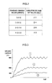
- Fig. 2 there is depicted by way of example a table that correlates the standard current values and the capacitor voltage set values in the indirect designation mode.
- the table is created on a memory included in the main control unit 28 and may be modified or updated if desired.
- the shown example provides four different standard current values, 500 amperes, 1,000 amperes, 2,000 amperes and 4,000 amperes which are correlated with voltage set values of the capacitor 12, 20 volts, 24 volts, 28 volts and 30 volts, respectively. In this manner, correlation is made such that a smaller standard current value leads to a lower capacitor voltage set value whereas a larger standard current value leads to a higher capacitor voltage set value.
- the user may designate a standard current value close to a set value of the welding current I w .
- the standard current value 2,000 amperes may be designated when setting the welding current I w to 1,700 amperes.
- the main control unit 28 sets the voltage of the capacitor 12 to 28 volts from the tablet, allowing the charging control unit 50 and the charging circuit 30 to charge the capacitor 12 to approx. 28 volts.
- the user designates a standard current value as a standard for setting the welding current whereby the voltage of the capacitor 12 is controlled to a value previously allocated to the designated standard current value within the power supply apparatus.
- Fig. 3 depicts waveforms of the welding current I w of this embodiment acquired in the case 1 ⁇ where the welding current I w has been set to 4,000 amperes with the capacitor 12 at 30 volts, the case 2 ⁇ where the welding current I w has been set to 2,000 amperes with the capacitor 12 at 28 volts, and the case 3 ⁇ where the welding current I w has been set to 1,000 amperes with the capacitor 12 at 24 volts.
- the current ripple period corresponds to the switching (ON-OFF) period of the PWM controlled switching transistor 18.
- the welding current I w when the welding current I w is set to a large value, a rapid current rise can be achieved by setting the voltage of the capacitor 12 to a higher value. In this case, the current ripple may increase, but a less rate or influence of the ripple is ensured due to largeness of the welding current I w itself. On the contrary, when the welding current I w is set to a small value, a lower set voltage value of the capacitor 12 may bring about a slow current rise but instead ensures a sufficiently small current ripple.
- the direct designation mode of this embodiment complements the indirect designation mode in order to achieve a finer and freer setting of the relationship between the welding current and the capacitor voltage. For instance, when the welding current I w is set to 1,700 amperes in the above example, the direct designation mode enables the voltage of the capacitor 12 to be set to, e.g., 26 volts so as to enhance the ripple reduction or suppression effect. In the case of flow of a small welding current I w as well, the voltage of the capacitor 12 may be set to a slightly high level by the direct designation mode so as to obtain a desired current rise speed.
- a switching control may be provided such that the switching transistor 18 is continuously on as a sort of variable resistor during the current-supplying time.
- the welding current rise characteristics or current ripple characteristics can variably be regulated at will so as to, e.g., increase the current rise speed when a large welding current flows but to reduce the current ripple when a small welding current flows.
- the current rise characteristics or the current ripple characteristics are automatically regulated in conjunction with the setting of the current value of the welding current. This contributes to an improved quality management of the resistance welding.
Landscapes
- Engineering & Computer Science (AREA)
- Mechanical Engineering (AREA)
- Generation Of Surge Voltage And Current (AREA)
- Arc Welding Control (AREA)
Applications Claiming Priority (2)
| Application Number | Priority Date | Filing Date | Title |
|---|---|---|---|
| JP2000156592A JP4464531B2 (ja) | 2000-05-26 | 2000-05-26 | 抵抗溶接電源装置 |
| JP2000156592 | 2000-05-26 |
Publications (2)
| Publication Number | Publication Date |
|---|---|
| EP1157774A2 true EP1157774A2 (de) | 2001-11-28 |
| EP1157774A3 EP1157774A3 (de) | 2003-03-19 |
Family
ID=18661361
Family Applications (1)
| Application Number | Title | Priority Date | Filing Date |
|---|---|---|---|
| EP01304514A Withdrawn EP1157774A3 (de) | 2000-05-26 | 2001-05-23 | Leistungsversorgungsvorrichtung für Widerstandsschweissgerät |
Country Status (5)
| Country | Link |
|---|---|
| US (1) | US20010047982A1 (de) |
| EP (1) | EP1157774A3 (de) |
| JP (1) | JP4464531B2 (de) |
| KR (1) | KR100727373B1 (de) |
| CN (1) | CN1325776A (de) |
Cited By (1)
| Publication number | Priority date | Publication date | Assignee | Title |
|---|---|---|---|---|
| AT508601B1 (de) * | 2009-08-12 | 2015-05-15 | Fronius Int Gmbh | Widerstandsschweissverfahren und -anlage |
Families Citing this family (10)
| Publication number | Priority date | Publication date | Assignee | Title |
|---|---|---|---|---|
| US6825435B1 (en) * | 2002-03-12 | 2004-11-30 | Lyndon Brown | Power supply and control equipment for a resistance welding machine |
| JP4374039B2 (ja) * | 2007-06-14 | 2009-12-02 | ファナック株式会社 | スポット溶接システム及び溶接ガン閉速度調整方法 |
| KR101036655B1 (ko) * | 2008-10-23 | 2011-05-25 | 삼성중공업 주식회사 | 모터동작감지장치 |
| US20150076121A1 (en) * | 2011-09-13 | 2015-03-19 | Jeffrey Krupp | Two-Stage Switch-Mode Power Supply for Drawn-Arc Stud Welding |
| DE102012005959A1 (de) * | 2011-12-24 | 2013-06-27 | Robert Bosch Gmbh | Verfahren und Steuergerät zum Laden eines Zwischenkreiskondensators für ein Schweißgerät |
| JP2015015821A (ja) * | 2013-07-04 | 2015-01-22 | 三菱電機株式会社 | パワーコンディショナ |
| JP2016181544A (ja) * | 2015-03-23 | 2016-10-13 | ファナック株式会社 | 定電流制御電源およびレーザ発振器 |
| US10629563B2 (en) * | 2015-05-03 | 2020-04-21 | Kaijo Corporation | Ball forming device for wire bonder |
| CN109262125B (zh) * | 2018-09-25 | 2021-08-24 | 常州铭赛机器人科技股份有限公司 | 晶体管式电阻焊接电源系统及其控制方法 |
| IT202400000636A1 (it) * | 2024-01-16 | 2025-07-16 | Mirco Zenere | Saldatrice a resistenza |
Family Cites Families (5)
| Publication number | Priority date | Publication date | Assignee | Title |
|---|---|---|---|---|
| US2483691A (en) * | 1940-01-06 | 1949-10-04 | Raytheon Mfg Co | Condenser welding system |
| US2894113A (en) * | 1957-03-13 | 1959-07-07 | Honeywell Regulator Co | Welding method and device |
| JPS61212486A (ja) * | 1985-03-19 | 1986-09-20 | Matsushita Electric Ind Co Ltd | コンデンサ式抵抗溶接機 |
| DE3614271A1 (de) * | 1986-04-26 | 1987-10-29 | Kriegeskorte & Co Gmbh | Tragbares bolzenschweissgeraet |
| JPH11129077A (ja) * | 1997-10-29 | 1999-05-18 | Miyachi Technos Corp | 抵抗溶接電源装置 |
-
2000
- 2000-05-26 JP JP2000156592A patent/JP4464531B2/ja not_active Expired - Fee Related
-
2001
- 2001-04-19 KR KR1020010021129A patent/KR100727373B1/ko not_active Expired - Lifetime
- 2001-05-23 EP EP01304514A patent/EP1157774A3/de not_active Withdrawn
- 2001-05-24 US US09/863,398 patent/US20010047982A1/en not_active Abandoned
- 2001-05-28 CN CN01118950A patent/CN1325776A/zh active Pending
Cited By (1)
| Publication number | Priority date | Publication date | Assignee | Title |
|---|---|---|---|---|
| AT508601B1 (de) * | 2009-08-12 | 2015-05-15 | Fronius Int Gmbh | Widerstandsschweissverfahren und -anlage |
Also Published As
| Publication number | Publication date |
|---|---|
| US20010047982A1 (en) | 2001-12-06 |
| EP1157774A3 (de) | 2003-03-19 |
| JP4464531B2 (ja) | 2010-05-19 |
| JP2001334369A (ja) | 2001-12-04 |
| CN1325776A (zh) | 2001-12-12 |
| KR20010107548A (ko) | 2001-12-07 |
| KR100727373B1 (ko) | 2007-06-12 |
Similar Documents
| Publication | Publication Date | Title |
|---|---|---|
| US10543553B2 (en) | High current AC welder | |
| US8067714B2 (en) | Squeezing detection control method for consumable electrode arc welding | |
| CN104470669B (zh) | 焊丝馈送器电力应用系统和方法 | |
| CN104507618B (zh) | 极性感测焊接送丝器系统和方法 | |
| EP1157774A2 (de) | Leistungsversorgungsvorrichtung für Widerstandsschweissgerät | |
| CN104428096A (zh) | 焊接系统涌入电流控制系统 | |
| US8937263B2 (en) | Capacitive discharge welding power supply and capacitive discharge welder using the same | |
| US20030164357A1 (en) | Portable drawn arc stud welding apparatus and method providing high current output in short time intervals | |
| US4049946A (en) | Power supply for electric arc welding | |
| US6825435B1 (en) | Power supply and control equipment for a resistance welding machine | |
| US5218182A (en) | Constant current welding power supply with auxilary power source to maintain minimum output current levels | |
| US7288741B2 (en) | Arc welder | |
| US7286330B2 (en) | Power supply device and method having a spark prevention function | |
| CN107538106B (zh) | 焊机维弧装置 | |
| CN110773855A (zh) | 储能点焊机装置 | |
| GB2297934A (en) | Stud welding apparatus | |
| JP3981208B2 (ja) | アーク加工用電源装置 | |
| US20010023857A1 (en) | Resistance welding power supply apparatus | |
| US20070120541A1 (en) | Capacitor insulating power supply | |
| JPH0332019B2 (de) | ||
| KR950006365B1 (ko) | 방전가공기의 전원 극성 절환회로 | |
| JPS6253265B2 (de) | ||
| GB1599076A (en) | Apparatus for recharging dry electric power cells | |
| JP3468114B2 (ja) | 高圧電源装置 | |
| JPS6351792B2 (de) |
Legal Events
| Date | Code | Title | Description |
|---|---|---|---|
| PUAI | Public reference made under article 153(3) epc to a published international application that has entered the european phase |
Free format text: ORIGINAL CODE: 0009012 |
|
| AK | Designated contracting states |
Kind code of ref document: A2 Designated state(s): AT BE CH CY DE DK ES FI FR GB GR IE IT LI LU MC NL PT SE TR |
|
| AX | Request for extension of the european patent |
Free format text: AL;LT;LV;MK;RO;SI |
|
| PUAL | Search report despatched |
Free format text: ORIGINAL CODE: 0009013 |
|
| AK | Designated contracting states |
Kind code of ref document: A3 Designated state(s): AT BE CH CY DE DK ES FI FR GB GR IE IT LI LU MC NL PT SE TR Designated state(s): AT BE CH CY DE DK ES FI FR GB GR IE IT LI LU MC NL PT SE TR |
|
| AX | Request for extension of the european patent |
Extension state: AL LT LV MK RO SI |
|
| RIC1 | Information provided on ipc code assigned before grant |
Ipc: 7B 23K 11/25 B Ipc: 7B 23K 11/26 B Ipc: 7B 23K 11/24 A |
|
| AKX | Designation fees paid |
Designated state(s): DE FR GB IT NL |
|
| STAA | Information on the status of an ep patent application or granted ep patent |
Free format text: STATUS: THE APPLICATION IS DEEMED TO BE WITHDRAWN |
|
| 18D | Application deemed to be withdrawn |
Effective date: 20030920 |