EP1158059B1 - Utilisation d'un rouleau de sole dans un procede de traitement thermique de diverses bandes metalliques dans un four vertical - Google Patents
Utilisation d'un rouleau de sole dans un procede de traitement thermique de diverses bandes metalliques dans un four vertical Download PDFInfo
- Publication number
- EP1158059B1 EP1158059B1 EP00304408A EP00304408A EP1158059B1 EP 1158059 B1 EP1158059 B1 EP 1158059B1 EP 00304408 A EP00304408 A EP 00304408A EP 00304408 A EP00304408 A EP 00304408A EP 1158059 B1 EP1158059 B1 EP 1158059B1
- Authority
- EP
- European Patent Office
- Prior art keywords
- wmin
- heat treating
- taper sections
- furnace
- hearth
- Prior art date
- Legal status (The legal status is an assumption and is not a legal conclusion. Google has not performed a legal analysis and makes no representation as to the accuracy of the status listed.)
- Expired - Lifetime
Links
Images



Classifications
-
- C—CHEMISTRY; METALLURGY
- C21—METALLURGY OF IRON
- C21D—MODIFYING THE PHYSICAL STRUCTURE OF FERROUS METALS; GENERAL DEVICES FOR HEAT TREATMENT OF FERROUS OR NON-FERROUS METALS OR ALLOYS; MAKING METAL MALLEABLE, e.g. BY DECARBURISATION OR TEMPERING
- C21D9/00—Heat treatment, e.g. annealing, hardening, quenching or tempering, adapted for particular articles; Furnaces therefor
- C21D9/52—Heat treatment, e.g. annealing, hardening, quenching or tempering, adapted for particular articles; Furnaces therefor for wires; for strips ; for rods of unlimited length
- C21D9/54—Furnaces for treating strips or wire
- C21D9/56—Continuous furnaces for strip or wire
- C21D9/562—Details
- C21D9/563—Rolls; Drums; Roll arrangements
-
- F—MECHANICAL ENGINEERING; LIGHTING; HEATING; WEAPONS; BLASTING
- F27—FURNACES; KILNS; OVENS; RETORTS
- F27B—FURNACES, KILNS, OVENS OR RETORTS IN GENERAL; OPEN SINTERING OR LIKE APPARATUS
- F27B9/00—Furnaces through which the charge is moved mechanically, e.g. of tunnel type; Similar furnaces in which the charge moves by gravity
- F27B9/14—Furnaces through which the charge is moved mechanically, e.g. of tunnel type; Similar furnaces in which the charge moves by gravity characterised by the path of the charge during treatment; characterised by the means by which the charge is moved during treatment
-
- F—MECHANICAL ENGINEERING; LIGHTING; HEATING; WEAPONS; BLASTING
- F27—FURNACES; KILNS; OVENS; RETORTS
- F27B—FURNACES, KILNS, OVENS OR RETORTS IN GENERAL; OPEN SINTERING OR LIKE APPARATUS
- F27B9/00—Furnaces through which the charge is moved mechanically, e.g. of tunnel type; Similar furnaces in which the charge moves by gravity
- F27B9/28—Furnaces through which the charge is moved mechanically, e.g. of tunnel type; Similar furnaces in which the charge moves by gravity for treating continuous lengths of work
-
- F—MECHANICAL ENGINEERING; LIGHTING; HEATING; WEAPONS; BLASTING
- F27—FURNACES; KILNS; OVENS; RETORTS
- F27D—DETAILS OR ACCESSORIES OF FURNACES, KILNS, OVENS OR RETORTS, IN SO FAR AS THEY ARE OF KINDS OCCURRING IN MORE THAN ONE KIND OF FURNACE
- F27D3/00—Charging; Discharging; Manipulation of charge
- F27D3/02—Skids or tracks for heavy objects
- F27D3/026—Skids or tracks for heavy objects transport or conveyor rolls for furnaces; roller rails
Definitions
- the present invention relates to use of a hearth roll in a heating or soaking furnace of a vertical heat treating furnace and to a method for heat treating a variety of metal strips in such a furnace.
- Vertical heat treating furnaces are ordinarily divided into respective sections of a heating furnace, a soaking furnace, and a cooling furnace, and a predetermined heat treatment cycle is performed.
- the heating furnace and the soaking furnace contained in the vertical heat treating furnace are described as one set of equipment in the present invention, and are referred to as "a heating/soaking furnace.”
- the vertical heat treating furnace includes a plurality of hearth rolls as transfer rolls located on the upper portion and the lower portion of the vertical heat treating furnace, and a metal strip is passed while being suspended by these hearth rolls and subjected to a necessary heat treatment in the process.
- metal strips to be passed are not always flat and include a bent portion and a locally extended portion, a transfer problem such as meandering and the like is liable to occur while they are being passed.
- Japanese Unexamined Patent Application Publications Nos. 55-100919 and 57-137431 disclose controlling the crown of a roll using the thermal expansion in a hearth roll by devising (designing/modifying) the inner structure of the hearth roll.
- Japanese Unexamined Patent Application Publications Nos. 8-199247, 7-138656, 58-120739, and 52-136812 disclose conventional examples in which the shape of a hearth roll itself is devised. These publications disclose a hearth roll having a one-stepped taper, which is arranged such that the central portion of the hearth roll has a flat shape or a crown shape, with both sides of the roll having a taper.
- a line was conventionally operated with a sheet width ranging from 800 mm to 1500 mm. Recently, it has been required to pass a steel sheet having a sheet width of about 800-1500 mm, and sometimes a steel sheet having a sheet width larger than this, in the same line.
- An optimum roll shape has been known as to the one-stepped taper roll and used as an effective means for preventing meandering and buckling in the operation in the conventional range of sheet width.
- the roll shape cannot be used as it is in a wide range of sheet widths having a ratio of maximum to minimum sheet width of, for example, 2 or more.
- the one-stepped taper roll has a problem in that while it can effectively prevent the occurrence of buckling in a wide metal strip when the inclination of a taper is reduced, meandering is liable to occur in a narrow metal strip.
- buckling is liable to occur in a wide metal strip, particularly when its thickness is thin.
- a metal strip can be passed stably in a vertical heat treating furnace even by a conventional hearth roll to a certain extent when the metal strip is in a steady state in which it is passed at an approximately constant speed.
- the sheet passing speed is often changed considerably. Meandering and buckling often occur when the speed is changed (by changes corresponding to 40-50% of a steady speed).
- an ordinary sheet passing speed is about 200-400 m/min in a steady state.
- the present invention can cope with the transfer of a steel strip in a wide range of sheet width only by simply optimizing a hearth roll at a low equipment cost without the need for remodeling equipment on a large scale.
- the present invention is preferable to a heating/soaking furnace of a vertical heat treating furnace for treating a steel strip having a wide range of sheet width in which a rate of maximum to minimum sheet width is 2 or more.
- the inventors have discovered that meandering and buckling can be prevented by optimizing the shape and disposition of two-stepped taper rolls more effectively than conventional taper rolls also in correspondence particularly to a wide range of sheet width and to a change in speed.
- the taper sections include first and second taper sections, wherein the inclination of each of the first taper sections continuous to the flat section is larger than the inclination of each of the second taper sections further continuous to each of the first taper sections.
- the length Lc (mm) of the flat section and the length L1 (mm) of each of the first taper sections are related according to the following formulas (1) and (2), in terms of the minimum width Wmin and maximum width Wmax of the metal strip.
- the inclination R1 of each of the first taper sections is within the range of 0.2 x 10 -3 to 10 x 10 -3
- the inclination R2 of each of the second taper sections is within the range of 0.05 x 10 -3 to 4 x 10 -3 .
- the hearth rolls at the inlet of the vertical heat treating furnace satisfy the following formulas (3), (4), (7) and (8), and the hearth rolls from the intermediate portion to the outlet of the furnace satisfy the following formulas (5), (6), (9) and (10), as well as the lengths Lc and (Lc + 2 x L1) are increased from the inlet to the outlet of the furnace, stepwise or sequentially, in the hearth roll groups of the respective ones of upper rolls and lower rolls disposed side by side in the furnace and the inclinations R1 and R2 of the tapers are reduced from the inlet to the outlet of the furnace stepwise or sequentially.
- Wmin ⁇ Lc ⁇ Wmin Wmin ⁇ Lc + 2 x L1 ⁇ Wmax - 400 0.5 Wmin ⁇ Lc ⁇ 0.7 Wmin Wmin ⁇ Lc + 2 x L1 ⁇ (Wmin + Wmax - 400)/2 0.7 Wmin ⁇ Lc ⁇ Wmin (Wmin + Wmax - 400)/2 ⁇ Lc + 2 x L1 ⁇ Wmax - 400 3.0 x 10 -3 ⁇ R1 ⁇ 10 x 10 -3 1.2 x 10 -3 ⁇ R2 ⁇ 4.0 x 10 -3 0.2 x 10 -3 ⁇ R1 ⁇ 3.0 x 10 -3 0.05 x 10 -3 ⁇ R2 ⁇ 1.2 x 10 -3 where, Wmin is the (minimum) width (mm) of the narrowest metal strip being subjected to heat treatment and lies in the range from 500 to 1000mm, and Wmax is the (maximum) width (mm) of the widest metal strip being subjected to heat
- the stepwise increase of the length means that the value of Lc and the like is increased in the next roll in adjacent rolls (when upper rolls and lower rolls are handled as belonging to different roll systems, adjacent rolls in each system) at least any one position from the inlet to the outlet of the furnace, while the same value may be sometimes set in the adjacent rolls.
- This is also applicable to the case in which the inclinations R1 and R2 are reduced stepwise. It is contemplated as a typical case of the above arrangement to separate the interior of the furnace into several blocks and to change the value among the blocks.
- a method of treating a metal strip using hearth rolls and a vertical heat treating furnace as described above is also provided.
- the flat section 12 may be approximately flat and, for example, may be formed as a gentle curved surface having a radius of curvature of, for example, at least 100 m.
- the boundary 18 between the flat section 12 and each of the first taper sections 14, and the boundary 20 between each of the first taper sections 14 and each of the second taper sections 16 are formed in a round shape without any corner as a catching part. It is also preferable that these boundaries 18, 20 are arranged as a convex curve section 22 and a concave curve section 24, respectively. However, because it is desirable to make the connecting portions thereof as gentle as possible, it is preferable to set the radii of curvature thereof to at least 20 m, respectively.
- the two-stepped taper sections 14, 16 on both sides of the flat section 12 are not necessarily symmetrical and the inclinations of the two-stepped taper sections 14, 16 on the right and left sides may be varied, or the widths of the taper sections 14, 16 may be varied.
- FIG. 2 schematically shows a typical vertical heat treating furnace to which the present invention is applied.
- the vertical heat treating furnace 30 comprises a heating furnace 32 for performing heating, and a soaking furnace 34 for performing soaking, and these furnaces 32, 34 are arranged continuously.
- a preheating furnace may be disposed in front of the heating furnace 32.
- the hearth rolls of the preheating furnace can be regarded as the same as a group of hearth rolls on the inlet side of the heating furnace.
- a metal strip 36 enters the furnace from the inlet of the vertical heat treating furnace 30. That is, the metal strip 36 enters the heating furnace 32 and is passed while being suspended by upper hearth rolls 38 and lower hearth rolls 40 disposed on the upper side and the lower side, respectively, of the furnace.
- the metal strip 36 which is passed in the furnace, is heated by heating elements 42. While the heating elements 42 are shown only partly in Fig. 2 for simplicity, a plurality of the heating elements 42 are disposed at desired positions in the heating furnace 32 and the soaking furnace 34.
- a radiant tube or the like can be used as a heating element.
- a shield plate 44 is conventionally interposed between a hearth roll 10 and a heating element 42, such as a radiant tube, so that the crown of the hearth roll 10 is not deformed by the radiant heat from the heating element 42.
- the most effective position of the shield plate 44 also has been examined. As a result, it has been confirmed that the effect of the shield plate 44 is not significant in the latter half section of the heating furnace 32 and in the soaking furnace 34 where the temperature of the metal strip 36 approaches the temperature in the furnace and the temperature of the heating element 42. It has also been confirmed that the shield plate 44 has a large effect in the former half section of the heating furnace 32 where the temperature of the metal strip 36 is considerably lower than the temperature in the furnace and the temperature of the heating element 42.
- both of the ends of the hearth roll 10 located in the former half section of the heating furnace 32 are heated by the heating element 42, while the central portion of the hearth roll 10 is kept at a low temperature by the metal strip 36 having a low temperature. Accordingly, the hearth roll 10 is liable to develop a concave crown, whereby the metal strip 36 is liable to be meandered.
- Fig. 3 graphically illustrates how meandering and buckling properties can be improved, and how operation can be stabilized, by the two-stepped taper roll used according to the present invention as compared to use of a conventional one-stepped taper roll.
- the abscissa represents the sheet width of a metal strip passed in the furnace and the ordinate represents the sheet thickness of the metal strip.
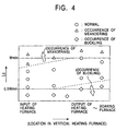
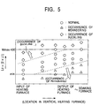
- the taper angle of the roll, the radius of curvature of the taper boundary of the roll, and the like of the two-stepped taper roll employed in Fig. 3 meet the above-described preferred conditions according to the present invention. Further, the occurrence of respective sheet passing problems was determined depending upon whether the problems were caused when the sheet passing speed was lowered by 50% as compared with an ordinary sheet passing speed (300 m/min). This also is applied likewise to Figs. 4 and 5 which are described below.
- the conventional one-stepped taper roll can approximately prevent meandering and buckling and stabilize operation when the maximum/minimum ratio of sheet width of a metal strip (Wmax/Wmin) is less than 1-2, at most.
- Wmax/Wmin is 2 or more, the occurrence of buckling cannot be completely prevented in a metal strip having a large width and a small thickness even if the length of the flat portion of the hearth roll, the taper length, and the like thereof are variously adjusted.
- meandering and buckling can be effectively prevented over a wide range in which Wmax/Wmin is 2 or more, so long as satisfactory conditions are used for the hearth roll.
- the optimum value of the length Lc of the flat portion of a hearth roll 10 having a two-stepped taper as shown in Fig. 1 is determined based on the minimum sheet width Wmin of a metal sheet to be passed, and it is required to set the length Lc as follows: 0.5 Wmin ⁇ Lc ⁇ Wmin
- the shape of a sheet is ordinarily improved in the latter half section of the vertical heat treating furnace 30 and meandering is unlikely to occur. Therefore, it has been found that it is effective to set Lc to a larger value within the range of 0.7 ⁇ Wmin or more to prevent buckling.
- Lc is set larger from the central portion of the heating furnace 32 to the soaking furnace 34 as compared with the inlet of the heating furnace 32 as shown in Fig. 4, the problem of buckling is often caused in a wide metal strip, even if the tapers on both of the sides of the hearth roll are variously adjusted.
- the maximum value of Lc does not exceed Wmin. This is because if Lc is set larger than Wmin, meandering is caused from the central portion of the heating furnace 32 to the soaking furnace 34 in case of Wmin, while the shape of the metal strip is corrected from the central portion of the heating furnace 32 to the soaking furnace 34.
- Lc + 2 ⁇ L1 must be set larger than the minimum width Wmin of a metal strip to prevent the meandering of a narrow metal strip. Further, when Lc + 2 ⁇ L1 is larger than the maximum width Wmax - 400, buckling is likely to occur in a wide metal strip even if any value is selected as the inclinations R1 and R2 of the two-stepped taper portions of the hearth roll.
- Fig. 5 shows the optimum range of Lc + 2 ⁇ L1 and how meandering and buckling are caused when the optimum range is not satisfied. It has been found that it is difficult to completely prevent the occurrence of meandering and buckling unless Lc + 2 ⁇ L1 is set properly, even if any value is selected as R1 and R2. Further, it has become apparent that the inclinations R1 and R2 of the taper portions are preferably set when the relationship of R1 > R2 is achieved, R1 is set to a value from 0.2 ⁇ 10 -3 to 10 ⁇ 10 -3 and R2 is set to a value from 0.05 ⁇ 10 -3 to 4 ⁇ 10 -3 .
- R1 and R2 it is more preferable for them to satisfy the following relationships: 3.0 ⁇ 10 -3 ⁇ R1 ⁇ 10 ⁇ 10 -3 and 1.2 ⁇ 10 -3 ⁇ R2 ⁇ 4.0 ⁇ 10 -3 , respectively on the inlet of the furnace, and to satisfy the following relationships: 0.2 ⁇ 10 -3 ⁇ R1 ⁇ 3.0 ⁇ 10 -3 and 0.05 ⁇ 10 -3 ⁇ R2 ⁇ 1.2 ⁇ 10 -3 , respectively, on the outlet of the furnace.
- the inclinations R1 and R2 are set as described above because it is preferable to put greater emphasis on the prevention of buckling in the latter half section of the furnace in design likewise in the case of Lc and other parameters.
- the respective values of L1 and Lc + 2 ⁇ L1 are sequentially increased from the inlet to the outlet of the vertical heat treating furnace 30, or, in some embodiments, made equal to each other.
- the values may be varied in the former half section and the latter half section of the vertical heat treating furnace 30 by dividing the interior the furnace into the two portions. Otherwise, the values may be sequentially increased at about three to five steps in some embodiments. Further, the values may be sequentially and continuously increased in other embodiments.
- TABLE 1 shows the relationship between Lc and L1 of a hearth roll applied in the vertical heat treating furnace for the respective cases of metal strips which are passed through the furnace and whose minimum and maximum widths are Wmin and Wmax.
- TABLE 1 shows the minimum value (min), median value (mid) and maximum value (max) of L1 to each of the minimum value (min), median value (mid) and maximum value (max) of Lc as a matrix with respect to the respective cases of Wmin and Wmax.
- the values shown in the parentheses are not actually used.
- Fig. 6 shows the reduction of the operation rate of equipment caused by meandering and buckling when a vertical heat treating furnace embodying the present invention is used and also when a conventional vertical furnace is used.
- a steel sheet is meandered a large amount, or when it is greatly drawn, operation is finally carried out at a lowered speed.
- the degree of meandering and buckling is greatly increased, the steel sheet must be subjected to a countermeasure by stopping the operation and lowering the temperature of the furnace, which reduces the operation rate of the equipment.
- the reduction of the operation rate of the equipment is represented by the rate between a time during which the equipment is interrupted by meandering and buckling and a working time.
- the reduction of the operation rate which was conventionally about 3%, can be reduced to 0.5% or less by an embodiment of the present invention.
- the working time is typically represented as a possible operation time, which is determined by subtracting the out of work time, the setup change time and the like, from a calendar time.
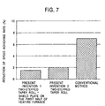
- Fig. 7 shows the reduction of the speed achieving rate of equipment caused by meandering and buckling when the vertical heat treating furnace using the present invention was employed and when the conventional vertical furnace was employed.
- the speed achieving rate is the rate between a speed calculated from a capacity of equipment and an actual operation rate, and it serves as an index representing a capacity in operation.
- meandering or buckling occurs in a steel sheet, while a countermeasure is typically employed to continue operation without the occurrence of serious disadvantages caused by speed reduction, the speed achieving rate is finally lowered and the desired amount of production cannot be achieved.
- the reduction of the speed achieving rate which was conventionally about 7%, can be reduced to about 2% by the embodiment of the present invention.
- the shape and size of hearth rolls in the vertical heat treating furnace that is, in the heating/soaking furnace can be optimized by the present invention and operation can be stably conducted without the occurrence of meandering and buckling in metal strips having a wide range of sheet width. As a result, the occurrence of problems such as the reduction of yield, line stopping, the reduction of line speed, and other problems can be prevented. No.
Landscapes
- Engineering & Computer Science (AREA)
- Mechanical Engineering (AREA)
- General Engineering & Computer Science (AREA)
- Chemical & Material Sciences (AREA)
- Physics & Mathematics (AREA)
- Thermal Sciences (AREA)
- Crystallography & Structural Chemistry (AREA)
- Materials Engineering (AREA)
- Metallurgy (AREA)
- Organic Chemistry (AREA)
- Heat Treatment Of Strip Materials And Filament Materials (AREA)
Claims (9)
- Utilisation d'un rouleau de sole (10 ; 38, 40) dans un four de chauffage/maintien à température (32, 34) d'un four de traitement thermique vertical (30) servant à traiter par la chaleur une variété de bandes de métal (36) dont la largeur varie d'une valeur minimale Wmin à une valeur maximale Wmax, le rouleau de sole comprenant une section plate (12) qui roule en une partie centrale du rouleau de sole et des sections coniques à deux niveaux (14, 16) qui roulent sur les côtés opposés de la section plate, les sections coniques comprenant des premières sections coniques (14) et des deuxièmes sections coniques (16), où l'inclinaison de chacune des premières sections coniques contiguës à ladite section plate est plus grande que l'inclinaison de chacune des deuxièmes sections coniques contiguës à chacune desdites premières sections coniques, caractérisée en ce que la longueur LC (mm) de ladite section plate (12) et la longueur L1 (mm) de chacune desdites premières sections coniques (14) satisfont les relations données par les formules (1) et (2) suivantes :
Wmin est la largeur (mm) des bandes de métal les plus étroites (36) soumises au traitement thermique et est comprise dans l'intervalle allant de 500 à 1 000 mm, et
Wmax est la largeur (mm) des bandes de métal les plus larges (36) soumises au traitement thermique et est comprise dans l'intervalle allant de 1 000 à 2 000 mm, et où Wmax/Wmin ≥ 2,0. - Utilisation d'un rouleau de sole (10 ; 38, 40) selon la revendication 1, dans laquelle une section courbée convexe (22) et une section courbée concave (24) sont formées au niveau d'une frontière (18) entre ladite section plate (12) et chacune desdites premières sections coniques (14), et au niveau d'une frontière (20) entre chacune desdites premières sections coniques (14) et chacune desdites deuxièmes sections coniques (16), respectivement, et chacune desdites sections convexe et concave a un rayon de courbure d'au moins 20 m.
- Utilisation d'un rouleau de sole (10 ; 38, 40) selon l'une quelconque des revendications 1 et 2, dans laquelle chacune desdites premières sections coniques (14) a une inclinaison R1 comprise dans l'intervalle allant de 0,2 x 10⁻³ à 10 x 10-3, et chacune desdites deuxièmes sections coniques (16) a une inclinaison R2 comprise dans l'intervalle allant de 0,05 x 10⁻³ à 4 x 10⁻³.
- Procédé de traitement par la chaleur d'une variété de bandes de métal (36) de largeur variable et ayant des largeurs W allant d'une valeur minimale Wmin à une valeur maximale Wmax, dans lequel on fait passer chaque bande (36) dans un four de traitement thermique vertical (30) comportant un four de chauffage/maintien à température (32, 34) dans lequel est placé au moins un rouleau de sole (10 ; 38, 40), le rouleau de sole (10 ; 38, 40) comprenant une section plate (12) qui roule en une partie centrale du rouleau de sole et des sections coniques à deux niveaux (14, 16) qui roulent sur les côtés opposés de la section plate, les sections coniques comprenant des premières sections coniques (14) et des deuxièmes sections coniques (16), où l'inclinaison de chacune des premières sections coniques contiguës à ladite section plate est plus grande que l'inclinaison de chacune des deuxièmes sections coniques contiguës à chacune desdites premières sections coniques, et caractérisé en ce que la longueur Le (mm) de ladite section plate (12) et la longueur L1 (mm) de chacune desdites premières sections coniques (14) satisfont les relations données par les formules (1) et (2) suivantes :
Wmin est la largeur des bandes de métal les plus étroites (36) soumises au traitement thermique et est comprise dans l'intervalle allant de 500 à 1 000 mm, et
Wmax est la largeur des bandes de métal les plus larges (36) soumises au traitement thermique et est comprise dans l'intervalle allant de 1 000 à 2 000 mm, et où Wmax/Wmin ≥ 2,0. - Procédé de traitement par la chaleur d'une variété de bandes de métal (36) de largeur variable selon la revendication 4, dans lequel, dans le rouleau de sole (10 ; 38, 40), sont formées une section courbée convexe (22) et une section courbée concave (24) au niveau d'une frontière (18) entre ladite section plate (12) et chacune desdites premières sections coniques (14), et au niveau d'une frontière (20) entre chacune desdites premières sections coniques (14) et chacune desdites deuxièmes sections coniques (16), respectivement, et chacune desdites sections convexe (22) et concave (24) a un rayon de courbure d'au moins 20 m.
- Procédé de traitement par la chaleur d'une variété de bandes de métal (36) de largeur variable selon la revendication 4 ou 5, dans lequel, dans le rouleau de sole (10 ; 38, 40), chacune desdites premières sections coniques (14) a une inclinaison R1 comprise dans l'intervalle allant de 0,2 x 10⁻³ à 10 x 10-3, et chacune des deuxièmes sections coniques (16) a une inclinaison R2 comprise dans l'intervalle allant de 0,05 x 10⁻³ à 4 x 10⁻³.
- Procédé de traitement par la chaleur d'une variété de bandes de métal (36) de largeur variable selon l'une quelconque des revendications 4 à 6, dans lequel des rouleaux de sole (10 ; 38, 40) sont placés à l'entrée du four de traitement thermique vertical (30) qui satisfont les formules (3) et (4) suivantes, des rouleaux de sole (10 ; 38, 40) sont placés depuis la partie intermédiaire jusqu'à la sortie, qui satisfont les formules (5) et (6) suivantes, et dans lequel les longueurs Lc et (Lc + 2 x L1) des rouleaux de sole augmentent de l'entrée à la sortie du four de traitement thermique vertical, pas à pas ou en séquence, dans les groupes de rouleaux de sole des rouleaux respectifs supérieurs et inférieurs placés côte à côte dans le four de traitement thermique vertical :
- Procédé de traitement par la chaleur d'une variété de bandes de métal (36) de largeur variable selon la revendication 7, dans lequel les rouleaux de sole (10 ; 38, 40) placés à l'entrée du four de traitement thermique vertical (30) satisfont en outre les formules (7) et (8) suivantes, les rouleaux de sole (10 ; 38, 40) placés depuis la partie intermédiaire jusqu'à la sortie satisfont en outre les formules (9) et (10) suivantes, et dans lequel les inclinaisons R1 et R2 des premières (14) et deuxièmes (16) sections coniques, respectivement, diminuent de l'entrée à la sortie du four de traitement thermique vertical, pas à pas ou en séquence :
- Procédé de traitement par la chaleur d'une variété de bandes de métal (36) de largeur variable selon la revendication 7 ou 8, dans lequel des plaques de séparation (44) sont placées au moins entre les rouleaux de sole (10 ; 38, 40) d'une ancienne demi-section du four de chauffage/maintien à température (32, 34) et des éléments chauffants (42).
Priority Applications (6)
| Application Number | Priority Date | Filing Date | Title |
|---|---|---|---|
| US09/572,449 US6238209B1 (en) | 2000-05-17 | 2000-05-17 | Hearth rolls for heating furnace and soaking furnace of vertical heat treating furnace and vertical heat treating furnace including hearth rolls |
| CA002308641A CA2308641C (fr) | 2000-05-17 | 2000-05-17 | Cylindres de chauffage et de maintien a temperature pour four de traitement thermique vertical, et four de traitement thermique vertical comprenant des cylindres |
| AT00304408T ATE300623T1 (de) | 2000-05-24 | 2000-05-24 | Verwendung einer herdrolle in einem verfahren zum wärmebehandeln verschiedener metallbänder in einem vertikalen durchlaufofen |
| EP00304408A EP1158059B1 (fr) | 2000-05-17 | 2000-05-24 | Utilisation d'un rouleau de sole dans un procede de traitement thermique de diverses bandes metalliques dans un four vertical |
| DE2000621534 DE60021534T2 (de) | 2000-05-24 | 2000-05-24 | Verwendung einer herdrolle in einem verfahren zum wärmebehandeln verschiedener metallbänder in einem vertikalen durchlaufofen |
| CNB001087363A CN1318614C (zh) | 2000-05-17 | 2000-05-31 | 立式热处理炉用炉底辊及使用该炉底辊的立式热处理炉 |
Applications Claiming Priority (4)
| Application Number | Priority Date | Filing Date | Title |
|---|---|---|---|
| US09/572,449 US6238209B1 (en) | 2000-05-17 | 2000-05-17 | Hearth rolls for heating furnace and soaking furnace of vertical heat treating furnace and vertical heat treating furnace including hearth rolls |
| CA002308641A CA2308641C (fr) | 2000-05-17 | 2000-05-17 | Cylindres de chauffage et de maintien a temperature pour four de traitement thermique vertical, et four de traitement thermique vertical comprenant des cylindres |
| EP00304408A EP1158059B1 (fr) | 2000-05-17 | 2000-05-24 | Utilisation d'un rouleau de sole dans un procede de traitement thermique de diverses bandes metalliques dans un four vertical |
| CNB001087363A CN1318614C (zh) | 2000-05-17 | 2000-05-31 | 立式热处理炉用炉底辊及使用该炉底辊的立式热处理炉 |
Publications (2)
| Publication Number | Publication Date |
|---|---|
| EP1158059A1 EP1158059A1 (fr) | 2001-11-28 |
| EP1158059B1 true EP1158059B1 (fr) | 2005-07-27 |
Family
ID=27427613
Family Applications (1)
| Application Number | Title | Priority Date | Filing Date |
|---|---|---|---|
| EP00304408A Expired - Lifetime EP1158059B1 (fr) | 2000-05-17 | 2000-05-24 | Utilisation d'un rouleau de sole dans un procede de traitement thermique de diverses bandes metalliques dans un four vertical |
Country Status (3)
| Country | Link |
|---|---|
| EP (1) | EP1158059B1 (fr) |
| CN (1) | CN1318614C (fr) |
| CA (1) | CA2308641C (fr) |
Families Citing this family (3)
| Publication number | Priority date | Publication date | Assignee | Title |
|---|---|---|---|---|
| WO2008150205A1 (fr) * | 2007-06-05 | 2008-12-11 | Sandvik Intellectual Property Ab | Four à rouleaux et rouleaux destinés à celui-ci |
| CN102021309B (zh) * | 2010-12-16 | 2012-01-18 | 山西太钢不锈钢股份有限公司 | 退火炉纤维辊的安装方法 |
| WO2025204232A1 (fr) * | 2024-03-27 | 2025-10-02 | Jfeスチール株式会社 | Procédé de fabrication de tôle en acier |
Family Cites Families (6)
| Publication number | Priority date | Publication date | Assignee | Title |
|---|---|---|---|---|
| US3070362A (en) * | 1961-03-02 | 1962-12-25 | Midland Ross Corp | Furnace roller |
| JPS52136812A (en) * | 1976-05-13 | 1977-11-15 | Nippon Kokan Kk <Nkk> | Roll for process line |
| JPH07173524A (ja) * | 1993-12-17 | 1995-07-11 | Nippon Steel Corp | 鋼板の連続焼鈍炉用ハースロール |
| JPH0931550A (ja) * | 1995-07-19 | 1997-02-04 | Kobe Steel Ltd | 連続熱処理設備における板幅制御方法 |
| JPH10298666A (ja) * | 1997-04-22 | 1998-11-10 | Sumitomo Metal Ind Ltd | 鋼帯の絞り込み防止方法および装置 |
| JP3533072B2 (ja) * | 1997-09-26 | 2004-05-31 | 新日本製鐵株式会社 | 熱処理炉用ハースロール |
-
2000
- 2000-05-17 CA CA002308641A patent/CA2308641C/fr not_active Expired - Fee Related
- 2000-05-24 EP EP00304408A patent/EP1158059B1/fr not_active Expired - Lifetime
- 2000-05-31 CN CNB001087363A patent/CN1318614C/zh not_active Expired - Lifetime
Also Published As
| Publication number | Publication date |
|---|---|
| CA2308641A1 (fr) | 2001-11-17 |
| CN1326007A (zh) | 2001-12-12 |
| EP1158059A1 (fr) | 2001-11-28 |
| CA2308641C (fr) | 2008-07-08 |
| CN1318614C (zh) | 2007-05-30 |
Similar Documents
| Publication | Publication Date | Title |
|---|---|---|
| EP0181830B1 (fr) | Procédé et dispositif pour chauffer un ruban métallique dans un four de recuit continu | |
| KR100206504B1 (ko) | 스테인레스강스트립제조장치 | |
| CN112916616B (zh) | 一种普通热轧带钢产线轧制薄板坯花纹板的工艺 | |
| US4878961A (en) | Method and system for controlling tension to be exerted on metal strip in continuous annealing furnace | |
| US6238209B1 (en) | Hearth rolls for heating furnace and soaking furnace of vertical heat treating furnace and vertical heat treating furnace including hearth rolls | |
| EP1158059A1 (fr) | Rouleaux de sole de four vertical comprenant un four chauffage et un four de maintien et four vertical équipé de ces rouleaux | |
| EP1167553A1 (fr) | Rouleaux devant être installés dans l'entrée ou la sortie d'une zone de trempe d'un four de recuit continu et ledit zone de trempe | |
| KR100511117B1 (ko) | 종형 열처리로의 가열·균열로용 하스 롤 및 그것을이용한 종형 열처리로 | |
| JP3465742B2 (ja) | 縦型熱処理炉用ハースロール及びそのハースロールを用いた縦型熱処理炉 | |
| JPH093553A (ja) | 熱処理炉の張力制御方法 | |
| JP3396932B2 (ja) | 金属帯の連続熱処理装置および連続熱処理方法 | |
| US4595357A (en) | Continuous annealing method and apparatus for cold rolled steel strips | |
| US4575053A (en) | Continuous annealing apparatus | |
| JPH11248360A (ja) | 鋼片の連続加熱装置および加熱方法 | |
| JP5332072B2 (ja) | 厚鋼板の熱処理方法およびその装置 | |
| JP3168753B2 (ja) | 金属帯連続処理ラインの直火還元加熱設備における通板方法 | |
| JP5022769B2 (ja) | 熱処理炉用鋼帯搬送ロール及び熱処理炉 | |
| MXPA00005466A (en) | Hearth roll for heating a furnace and reheating said furnace starting from a vertical thermal treatment furnace and this latter including the hearth rolls | |
| JPH08127819A (ja) | 方向性電磁鋼板の平坦化焼鈍方法と装置 | |
| JP2733885B2 (ja) | 鋼帯の連続熱処理方法 | |
| DE4203395C2 (de) | Verfahren zum Führen von aufzuheizenden Dünnbrammen, Blechen und Stahlbändern in Hochtemperatur-Rollenherdöfen und Hochtemperatur-Rollenherdofen zur Durchführung des Verfahrens | |
| JP2776033B2 (ja) | 連続焼鈍炉における鋼帯の蛇行防止方法 | |
| JPH08209252A (ja) | 金属帯板の連続熱処理炉 | |
| JP3588840B2 (ja) | 金属帯の熱処理炉 | |
| JPH11286731A (ja) | 電磁鋼板横型連続熱処理炉 |
Legal Events
| Date | Code | Title | Description |
|---|---|---|---|
| PUAI | Public reference made under article 153(3) epc to a published international application that has entered the european phase |
Free format text: ORIGINAL CODE: 0009012 |
|
| AK | Designated contracting states |
Kind code of ref document: A1 Designated state(s): AT BE DE FR GB IT Kind code of ref document: A1 Designated state(s): AT BE CH CY DE DK ES FI FR GB GR IE IT LI LU MC NL PT SE |
|
| AX | Request for extension of the european patent |
Free format text: AL;LT;LV;MK;RO;SI |
|
| 17P | Request for examination filed |
Effective date: 20020521 |
|
| AKX | Designation fees paid |
Free format text: AT BE DE FR GB IT |
|
| RAP1 | Party data changed (applicant data changed or rights of an application transferred) |
Owner name: JFE STEEL CORPORATION |
|
| 17Q | First examination report despatched |
Effective date: 20031106 |
|
| GRAP | Despatch of communication of intention to grant a patent |
Free format text: ORIGINAL CODE: EPIDOSNIGR1 |
|
| RTI1 | Title (correction) |
Free format text: USE OF A HEARTH ROLL IN A METHOD FOR HEAT TREATING A VARIETY OF METAL STRIPS IN A VERTICAL HEAT TREATING FURNACE INCLUDIN |
|
| RAP1 | Party data changed (applicant data changed or rights of an application transferred) |
Owner name: JFE ENGINEERING CORPORATION |
|
| GRAS | Grant fee paid |
Free format text: ORIGINAL CODE: EPIDOSNIGR3 |
|
| GRAA | (expected) grant |
Free format text: ORIGINAL CODE: 0009210 |
|
| AK | Designated contracting states |
Kind code of ref document: B1 Designated state(s): AT BE DE FR GB IT |
|
| REG | Reference to a national code |
Ref country code: GB Ref legal event code: FG4D |
|
| REG | Reference to a national code |
Ref country code: GB Ref legal event code: 732E |
|
| REF | Corresponds to: |
Ref document number: 60021534 Country of ref document: DE Date of ref document: 20050901 Kind code of ref document: P |
|
| RAP2 | Party data changed (patent owner data changed or rights of a patent transferred) |
Owner name: JFE STEEL CORPORATION |
|
| REG | Reference to a national code |
Ref country code: FR Ref legal event code: TP |
|
| ET | Fr: translation filed | ||
| PLBE | No opposition filed within time limit |
Free format text: ORIGINAL CODE: 0009261 |
|
| STAA | Information on the status of an ep patent application or granted ep patent |
Free format text: STATUS: NO OPPOSITION FILED WITHIN TIME LIMIT |
|
| 26N | No opposition filed |
Effective date: 20060428 |
|
| PGFP | Annual fee paid to national office [announced via postgrant information from national office to epo] |
Ref country code: GB Payment date: 20130522 Year of fee payment: 14 |
|
| GBPC | Gb: european patent ceased through non-payment of renewal fee |
Effective date: 20140524 |
|
| PG25 | Lapsed in a contracting state [announced via postgrant information from national office to epo] |
Ref country code: GB Free format text: LAPSE BECAUSE OF NON-PAYMENT OF DUE FEES Effective date: 20140524 |
|
| REG | Reference to a national code |
Ref country code: FR Ref legal event code: PLFP Year of fee payment: 17 |
|
| REG | Reference to a national code |
Ref country code: FR Ref legal event code: PLFP Year of fee payment: 18 |
|
| PGFP | Annual fee paid to national office [announced via postgrant information from national office to epo] |
Ref country code: IT Payment date: 20170522 Year of fee payment: 18 |
|
| REG | Reference to a national code |
Ref country code: FR Ref legal event code: PLFP Year of fee payment: 19 |
|
| PG25 | Lapsed in a contracting state [announced via postgrant information from national office to epo] |
Ref country code: IT Free format text: LAPSE BECAUSE OF NON-PAYMENT OF DUE FEES Effective date: 20180524 |
|
| PGFP | Annual fee paid to national office [announced via postgrant information from national office to epo] |
Ref country code: DE Payment date: 20190514 Year of fee payment: 20 |
|
| PGFP | Annual fee paid to national office [announced via postgrant information from national office to epo] |
Ref country code: BE Payment date: 20190417 Year of fee payment: 20 Ref country code: FR Payment date: 20190410 Year of fee payment: 20 |
|
| PGFP | Annual fee paid to national office [announced via postgrant information from national office to epo] |
Ref country code: AT Payment date: 20190425 Year of fee payment: 20 |
|
| REG | Reference to a national code |
Ref country code: DE Ref legal event code: R071 Ref document number: 60021534 Country of ref document: DE |
|
| REG | Reference to a national code |
Ref country code: BE Ref legal event code: MK Effective date: 20200524 |
|
| REG | Reference to a national code |
Ref country code: AT Ref legal event code: MK07 Ref document number: 300623 Country of ref document: AT Kind code of ref document: T Effective date: 20200524 |