EP1158085A2 - Dispositif d'application d'une mousse sur un substrat en mouvement - Google Patents
Dispositif d'application d'une mousse sur un substrat en mouvement Download PDFInfo
- Publication number
- EP1158085A2 EP1158085A2 EP01112223A EP01112223A EP1158085A2 EP 1158085 A2 EP1158085 A2 EP 1158085A2 EP 01112223 A EP01112223 A EP 01112223A EP 01112223 A EP01112223 A EP 01112223A EP 1158085 A2 EP1158085 A2 EP 1158085A2
- Authority
- EP
- European Patent Office
- Prior art keywords
- foam
- conduit
- settling tank
- applicator head
- generator
- Prior art date
- Legal status (The legal status is an assumption and is not a legal conclusion. Google has not performed a legal analysis and makes no representation as to the accuracy of the status listed.)
- Granted
Links
Images

Classifications
-
- D—TEXTILES; PAPER
- D06—TREATMENT OF TEXTILES OR THE LIKE; LAUNDERING; FLEXIBLE MATERIALS NOT OTHERWISE PROVIDED FOR
- D06B—TREATING TEXTILE MATERIALS USING LIQUIDS, GASES OR VAPOURS
- D06B23/00—Component parts, details, or accessories of apparatus or machines, specially adapted for the treating of textile materials, not restricted to a particular kind of apparatus, provided for in groups D06B1/00 - D06B21/00
- D06B23/20—Arrangements of apparatus for treating processing-liquids, -gases or -vapours, e.g. purification, filtration or distillation
-
- D—TEXTILES; PAPER
- D06—TREATMENT OF TEXTILES OR THE LIKE; LAUNDERING; FLEXIBLE MATERIALS NOT OTHERWISE PROVIDED FOR
- D06B—TREATING TEXTILE MATERIALS USING LIQUIDS, GASES OR VAPOURS
- D06B1/00—Applying liquids, gases or vapours onto textile materials to effect treatment, e.g. washing, dyeing, bleaching, sizing or impregnating
- D06B1/08—Applying liquids, gases or vapours onto textile materials to effect treatment, e.g. washing, dyeing, bleaching, sizing or impregnating from outlets being in, or almost in, contact with the textile material
-
- D—TEXTILES; PAPER
- D06—TREATMENT OF TEXTILES OR THE LIKE; LAUNDERING; FLEXIBLE MATERIALS NOT OTHERWISE PROVIDED FOR
- D06B—TREATING TEXTILE MATERIALS USING LIQUIDS, GASES OR VAPOURS
- D06B19/00—Treatment of textile materials by liquids, gases or vapours, not provided for in groups D06B1/00 - D06B17/00
- D06B19/0088—Treatment of textile materials by liquids, gases or vapours, not provided for in groups D06B1/00 - D06B17/00 using a short bath ratio liquor
- D06B19/0094—Treatment of textile materials by liquids, gases or vapours, not provided for in groups D06B1/00 - D06B17/00 using a short bath ratio liquor as a foam
Definitions
- the present invention relates to an apparatus for applying a chemical foam to a traveling substrate, and more particularly to such an apparatus that minimizes fluctuations in the application upon startup following a stoppage of the traveling substrate.
- Chemicals are commonly applied to traveling substrates in the form of a foam medium to obtain uniform dispersion of a thin application of the chemical.
- dyestuff, sizeing, and various treating chemicals are applied to textile fabrics of various sorts.
- the foam is normally applied under pressure to the substrate by having the foam delivery slot of the applicator in sealed contact with the substrate.
- the foam is fed from a generator through a delivery conduit to an applicator head at the location of application to the traveling substrate.
- the foam is a compressable medium, which results in a significant pressure drop between the generator and the delivery slot of the applicator head.
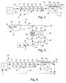
- a uniform thickness of foam can be applied with the foam being delivered at a constant rate and pressure to the substrate passing the applicator head slot at a uniform speed. This is illustrated in Fig. 1.
- the substrate is stopped, which may be for only seconds or may be for minutes or longer.
- the foam delivery must be stopped as well.
- the pressure differential of the foam within the delivery conduit equalizes, with the pressure at the applicator head being greater than during normal operation and the pressure at the generator end of the conduit being less than the normal delivery pressure from the generator.
- the higher than normal pressure at the applicator head slot results in a thicker coating delivery due to the higher foam pressure followed by reduction in the coating application as the lower than normal pressure upstream in the conduit further decreases as the foam travels through the conduit to the applicator head slot.
- FIG. 2 illustrates this wave-form fluctuating of coating application along a traveling substrate at startup after the traveling substrate has been stopped.
- the thickness of the coating C during this initial startup condition can vary from a fraction of the desired coating thickness to a multiple of the desired coating thickness and can extend over a length of, for example, 20 to 30 yards of the substrate.
- the thickness T of the coating C illustrated in Fig. 2 is exaggerated substantially for clarity of illustration.
- This coating application fluctuation at startup is not extreme enough under some coating applications to be of concern, but under some circumstances the variation in coating is unacceptable, resulting in a waste of coating and substrate material that must be discarded before the coated substrate is manufactured into a useable product.
- an apparatus for applying a chemical foam to a traveling substrate in a manner that minimizes fluctuation in coating thickness and obviates the waste and resulting environmental problems resulting from stops and starts of a traveling substrate as it travels past the foam applicating apparatus.
- a foam applicator head is disposed with a discharge slot extending transversely with respect to a traveling substrate for discharge of foam therefrom to the substrate.
- a foam delivery conduit communicates with and extends from the foam generator to the foam applicator head to transport foam from the generator to the applicator head with the dynamic pressure of the foam decreasing as the foam travels through the conduit.
- a plurality of normally open shut-off valves are spaced along the conduit, dividing it into a sequence of conduit sections.
- a valve controller is operable to close simultaneously the plurality of valves in response to a stoppage of the traveling substrate to, thereby, seal the foam in each conduit section to maintain a static pressure in each section corresponding to the dynamic pressure of the foam in that section during valve-open transport of foam.
- the controller is operable to open the valves simultaneously in response to resumption of substrate travel.
- a normally closed by-pass outlet is provided in the applicator head operated by a by-pass discharge valve that opens in response to stoppage of the traveling substrate.
- a by-pass conduit is provided for transporting foam from the generator to the applicator head bypassing the valves for continuous transport of foam to the applicator head and out the by-pass discharge outlet during stoppage of the substrate with the applicator head slot closed, thereby maintaining desired foam characteristics in the applicator head for resumption of foam application upon startup of the substrate.
- the by-pass conduit is substantially smaller in cross-section than the foam conduit so that only a minor portion of the normal quantity of foam is transported through the by-pass conduit.
- the by-pass conduit is open continuously both during normal operation and during stoppage, with the foam flow through the by-pass conduit combining with the flow through the foam delivery conduit during normal operation to provide the foam being applied to the traveling substrate.
- the cross-section of the by-pass conduit relative to the cross-section of the foam delivery conduit results in approximately 10% to 15% of the total flow of foam through both conduits being through the by-pass conduit.
- the applicator head includes a foam distribution chamber for distributing the foam uniformly from the foam conduit to the applicator head slot when the slot is open.
- a by-pass foam return conduit is provided for communicating between the discharge outlet of the applicator head and the foam generator for return of foam to the generator during stoppage of substrate travel. This avoids waste of the chemicals in the foam as well as avoiding environmental problems were the foam discharged to a drain.
- the foam return conduit is connected to a settling tank in which the foam deteriorates to a liquid form and is transported therefrom through a liquid return conduit to the foam generator for recycling.
- settling tanks there are two settling tanks with a settling tank input valve means operable to discharge foam from the foam return conduit to a selected one or the other of the settling tanks.
- a discharge valve means discharges the liquid material from one of the settling tanks while the other one is being filled.
- the settling tank input valve means and the discharge valve means are controlled by a valve control responsive to the level of fill in the settling tanks that closes flow to a filled settling tank, opens flow to the other settling tank, closes the flow from that other settling tank and opens flow from the filled tank to a liquid return conduit when the foam has settled to a liquid.
- a feed pump in the liquid return conduit pumps liquid from the settling tanks to the foam generator.
- the apparatus 10 includes a conventional foam generator 11, such as disclosed in U.S. Patent No. 4,237,818, to which air and a liquid chemical, such as a liquid dyestuff or sizeing or other treating material, is fed for the generation by the generator 11 of a foam material.
- the foam is transported through a foam conduit 12 to an applicator head 13, which preferably is in the form illustrated in U.S. Patent No.
- 4,655,056, having a parabolic distribution chamber 14 in which the foam is distributed uniformly across the length of an applicator head slot 15 that is disposed transversely in contact with a traveling substrate 16 for application of foam thereto in a uniform thickness.
- the foam is delivered under pressure, with the delivery pressure and flow being controlled conventionally to provide a selected uniform thickness of coating application.
- the traveling substrate 16 is in pressure resisting contact with the applicator head slot 15 so that the pressurized foam will enter the intersticies of the substrate in the case of a textile fabric or other similarly textured material.
- the applicator is of the type illustrated and described in my co-pending U.S. Patent Application Serial No. 09/175,651 having an inflatable bladder at the slot for closing the slot and a complementary discharge valve that opens when the slot valve is closed for discharge of foam from the applicator head so as to maintain a dynamic flow passage of foam through the applicator head.
- a plurality of sequential, normally open shut-off valves 17, 18, 19, 20, 21, and 22 are generally equally spaced along the length of the foam conduit 22 to divide the conduit into a plurality of conduit sections 23, 24, 25, 26, 27, 28 and 29.
- the valves are provided to close when the substrate stops traveling.
- a conventional sensor 30 senses the stoppage of substrate travel and a controller 31, responsive to the sensor, operates the valves 17-22 to simultaneously close all of the valves and, thereby, stop flow of foam through the conduit 12 and isolate the conduit sections 23-29 from each other so that the pressure in each section is generally the same as the dynamic pressure during open valve operation.
- each section When the valves close, the pressure in each section is equalized rather than having a pressure drop through the section, but the average pressure drop is substantially the same as the average pressure drop through the section during normal open valve operation.
- the number of valves can be varied depending on the length of the foam conduit and the desired length of the individual conduit sections. The shorter the length of each section, the less the pressure drop through the section such that when the valves are opened the initial pressure at the downstream end of the section will not be appreciably greater than the normal operating pressure and the pressure at the upstream end will not be appreciably less than the normal open valve operating pressure.
- the controller 31 When the substrate resumes travel after a stoppage, the controller 31 operates to open all of the valves 17-22 and flow of foam under pressure through the conduit 12 resumes. While there has been an equalization of the pressure drop in each section, the sections are short enough that this has a minimal effect on the delivery pressure of the foam as the foam reaches the applicator head 13 such that during the period of start-up, the pressure drop throughout the conduit 12 and the pressure at the applicator head 13 is substantially the same during normal running conditions.
- the coating application varies during start-up for an appreciable extent and in an appreciable amount.
- the coating may fluctuate between half to twice normal thickness and over an extended length that may be as much as 20 to 30 yards, resulting in that much waste of substrate and treating material.
- the apparatus 10 of the present invention results in a minimal fluctuation and that fluctuation only extending over a very short length of substrate, as little as one or two feet.
- the present invention provides a by-pass conduit 32 communicating with the foam delivery conduit 12 upstream of the first conduit valve 17 and downstream of the last conduit valve 22.
- This bypass conduit 32 is relatively small in cross-section in comparison with the foam delivery conduit 12.
- the foam delivery conduit 12 may, for example, be one and one-half inches in diameter and the by-pass conduit 32 is of a size that during normal open valve operation only approximately 10-15% of the foam flow will pass through the by-pass conduit. It is only necessary that the by-pass conduit 32 be of a size sufficient to deliver enough foam to the applicator head 13 to prevent stagnation of foam in the applicator head 13.
- a discharge outlet 33 is provided in the applicator head 13 and has a discharge valve disposed thereat and openable under control of the controller 31 in response to stoppage of the traveling substrate to discharge foam from the applicator head 13 as foam is being fed to the applicator head through the by-pass conduit 32, thereby maintaining a dynamic foam condition in the applicator head 13.
- the foam passing through the discharge valve 34 may be discharged to a drain as illustrated in Fig. 4. However, it is preferable to recycle the discharged foam.
- a foam return conduit 35 is disposed communicating between the by-pass discharge outlet 33 and the foam generator 11, with a pump 36 disposed in the return conduit 35 for pumping the discharged foam from the applicator head 13 to the generator 11.
- the discharged foam is in a foamed condition when it returns to the generator and can be recycled, with the addition of whatever small amount of air and liquid chemical may be necessary to maintain the desired condition of the foam that is exiting the generator 11.
- the foam is not recycled to the generator 11 in a foamed condition. Rather, the foam is freshly generated in the generator 11 so that proper control of the foam production can be obtained without any problem in the condition of the foam that would otherwise be returned to the generator from the applicator head 13.
- the return conduit 35 communicates with a pair of oppositely open and closed valves 37 and 38. Each of these valves 37 and 38 open into the top of a respective open settling tank 39 and 40.
- the first valve 37 is opened to the first settling tank 39, the discharge foam-will flow into that settling tank 39.
- the second valve 38 of the pair is closed so that there is no flow into its settling tank 40.
- Each of the tanks 39 and 40 has a lower level sensor 41 and an upper level sensor 42 to sense the level of foam in the settling tank.
- a conventional tank controller 43 is connected to the sensors 41 and 42 for opening and closing of the settling tank valves 37 and 38.
- a liquid return conduit 44 communicates between the settling tanks 39, 40 and the foam generator 11 and has a component 45 and 46 connected to each of the settling tanks 39 and 40 with liquid return valves 47 and 48 in each of the conduit components 45 and 46. These valves 47 and 48 remain closed until the foam in a respective settling tank 39 and 40 has degenerated from foam to a liquid and is in condition for return to the generator 11. These return valves 47 and 48 may be timed or may be controlled by the tank controller 43 or may be manually manipulated depending on the circumstances. Included in the liquid return conduit 44 is a pump 49 to which the components 45 and 46 of the liquid return conduit 44 communicate. This return pump 49 serves to pump the liquid through the return conduit 44 to the generator 11. Between the pump 49 and the generator 11 is a shut-off valve 50 that may be manually operated or automatically operated in response to the filling conditions of the settling tanks 39 and 40 to stop flow of recirculating liquid from the settling tanks to the generator.
- foam produced by the generator 11 is transported through the foam delivery conduit 12 and by-pass conduit 32 to the applicator head 13 in which the foam is uniformly distributed by the distribution chamber 14 and passes through the applicator head slot 15 to the traveling substrate 16 to apply a uniform thickness of foam.
- the discharge valve 34 is closed so that all of the foam is delivered through the applicator head slot 15 and none is either recirculated or discharged to a drain.
- the substrate sensor 30 senses the stoppage and sends a signal to the controller 31 which then simultaneously closes all of the foam conduit valves 17-22, stopping flow and maintaining the existing pressure in each of the conduit sections 23-29 while foam continues to flow through the by-pass conduit 32 into the applicator head 13.
- the controller 31 also opens the discharge valve 34 to allow discharge of foam from the applicator head and, thereby, maintain dynamic conditions in the applicator head 13.
- the discharging foam is transported through the return conduit 35 and through the open one of the two settling tank valves 37 and 38 into the respective settling tank 39 or 40.
- the substrate sensor 30 When the substrate sensor 30 senses that the substrate has resumed travel, it sends a signal to the controller 31, which operates to simultaneously open the valves 17-22 and the applicator head slot 15 while closing the by-pass discharge valve 34, thereby recreating the normal operating condition for applying uniform thickness foam to the traveling substrate 16.
- the settling tank to which the foam is being discharged will begin to fill the tank. Full filling of the tank may occur during one or several stoppage cycles, but in any event when the foam rises to the level of the upper level sensor 42 of the respective tank, the tank controller 43 will switch the settling tank valves 37 and 38 to start filling the other settling tank.
- the respective return valve 47 will be opened and the return pump 49 activated and the shut-off valve 50 opened to discharge the settled liquid back into the foam generator 11 for regeneration and circulation of the foam.
Landscapes
- Engineering & Computer Science (AREA)
- Textile Engineering (AREA)
- Coating Apparatus (AREA)
- Application Of Or Painting With Fluid Materials (AREA)
Applications Claiming Priority (2)
| Application Number | Priority Date | Filing Date | Title |
|---|---|---|---|
| US577541 | 2000-05-24 | ||
| US09/577,541 US6508882B1 (en) | 2000-05-24 | 2000-05-24 | Apparatus for applying a chemical foam to a traveling substrate |
Publications (3)
| Publication Number | Publication Date |
|---|---|
| EP1158085A2 true EP1158085A2 (fr) | 2001-11-28 |
| EP1158085A3 EP1158085A3 (fr) | 2004-04-28 |
| EP1158085B1 EP1158085B1 (fr) | 2005-10-19 |
Family
ID=24309166
Family Applications (1)
| Application Number | Title | Priority Date | Filing Date |
|---|---|---|---|
| EP01112223A Expired - Lifetime EP1158085B1 (fr) | 2000-05-24 | 2001-05-18 | Dispositif d'application d'une mousse sur un substrat en mouvement |
Country Status (3)
| Country | Link |
|---|---|
| US (1) | US6508882B1 (fr) |
| EP (1) | EP1158085B1 (fr) |
| DE (1) | DE60114082T2 (fr) |
Cited By (1)
| Publication number | Priority date | Publication date | Assignee | Title |
|---|---|---|---|---|
| EP1384807A3 (fr) * | 2002-07-25 | 2005-04-13 | Gaston Systems, Incorporated | Applicateur des fluides |
Families Citing this family (4)
| Publication number | Priority date | Publication date | Assignee | Title |
|---|---|---|---|---|
| US7416370B2 (en) * | 2005-06-15 | 2008-08-26 | Lam Research Corporation | Method and apparatus for transporting a substrate using non-Newtonian fluid |
| US20080254700A1 (en) * | 2007-04-11 | 2008-10-16 | Balthes Garry E | Process for making fibrous board |
| DE102007020095A1 (de) * | 2007-04-26 | 2008-10-30 | Nordson Corporation, Westlake | Vorrichtung und Verfahren zum Schaumauftrag auf Substrate mit großer Breite |
| US9091021B2 (en) | 2010-10-12 | 2015-07-28 | Oasis Dyeing Systems, Llc | Method of dyeing cellulosic substrates |
Family Cites Families (5)
| Publication number | Priority date | Publication date | Assignee | Title |
|---|---|---|---|---|
| US4237818A (en) | 1978-12-15 | 1980-12-09 | Gaston County Dyeing Machine Company | Means for applying treating liquor to textile substrate |
| US4402200A (en) | 1981-09-04 | 1983-09-06 | Gaston County Dyeing Machine Company | Means for applying foamed treating liquor |
| US4420510A (en) * | 1982-03-23 | 1983-12-13 | Weyerhaeuser Company | Method for applying a foamed adhesive under start-stop conditions |
| US4655056A (en) | 1985-06-11 | 1987-04-07 | Gaston County Dyeing Machine Co. | Foamed treating liquor applicator |
| US6432202B1 (en) * | 1998-10-20 | 2002-08-13 | Gaston Systems, Inc. | Textile yarn slashing system |
-
2000
- 2000-05-24 US US09/577,541 patent/US6508882B1/en not_active Expired - Lifetime
-
2001
- 2001-05-18 EP EP01112223A patent/EP1158085B1/fr not_active Expired - Lifetime
- 2001-05-18 DE DE60114082T patent/DE60114082T2/de not_active Expired - Lifetime
Cited By (1)
| Publication number | Priority date | Publication date | Assignee | Title |
|---|---|---|---|---|
| EP1384807A3 (fr) * | 2002-07-25 | 2005-04-13 | Gaston Systems, Incorporated | Applicateur des fluides |
Also Published As
| Publication number | Publication date |
|---|---|
| DE60114082T2 (de) | 2006-07-20 |
| DE60114082D1 (de) | 2006-03-02 |
| EP1158085A3 (fr) | 2004-04-28 |
| EP1158085B1 (fr) | 2005-10-19 |
| US6508882B1 (en) | 2003-01-21 |
Similar Documents
| Publication | Publication Date | Title |
|---|---|---|
| KR940011052A (ko) | 2-성분 분배 시스템에서 점성의 변화를 보정하기 위한 방법 및 장치 | |
| CA1195490A (fr) | Systeme a colle thermofusible | |
| JP2787576B2 (ja) | 液流染色機により繊維材料を処理する方法およびこの方法を実施するための装置 | |
| JP4711587B2 (ja) | 吹込成形剤の供給システム | |
| US4967957A (en) | Injection mixer | |
| US6261486B1 (en) | Process and device for the production of polyurethane moldings by the shot process | |
| US6508882B1 (en) | Apparatus for applying a chemical foam to a traveling substrate | |
| US4628861A (en) | Metering and proportioning system for a two-component liquid resin and liquid hardener adhesive | |
| US5066428A (en) | Foam generating apparatus | |
| US5173120A (en) | Coating apparatus having a partitioned coating chamber | |
| CN111434390A (zh) | 一种狭缝式涂布装置 | |
| CN1161187C (zh) | 向行进基材涂布泡沫材料的涂层机 | |
| KR20160033026A (ko) | 도포기, 도포 장치, 및 도포 방법 | |
| US3341124A (en) | Spraying method and apparatus | |
| JPH07241842A (ja) | 無端ポリウレタン成形物の製造方法および装置 | |
| CA1073198A (fr) | Machine a imprimer electrostatique avec systeme et methode ameliores de developpement sur tissu | |
| US20060051509A1 (en) | Process and equipment for uniform coating medium of treatment on materials in the form of rope | |
| EP1149674A2 (fr) | Procédé et appareil pour la pressurisation de composants réactionelles coulantes | |
| JPH08229939A (ja) | 二成分発泡材料を配量する方法および装置 | |
| JPS6048160A (ja) | 二液混合吐出方法及び装置 | |
| JP2548547Y2 (ja) | 二液混合供給装置 | |
| CN204224916U (zh) | 一种喷涂移动纤维幅材的装置 | |
| KR102907138B1 (ko) | 가압탱크의 순환장치 | |
| JPH11333351A (ja) | 塗布装置 | |
| CN218486451U (zh) | 调温装置及涂布系统 |
Legal Events
| Date | Code | Title | Description |
|---|---|---|---|
| PUAI | Public reference made under article 153(3) epc to a published international application that has entered the european phase |
Free format text: ORIGINAL CODE: 0009012 |
|
| AK | Designated contracting states |
Kind code of ref document: A2 Designated state(s): AT BE CH CY DE DK ES FI FR GB GR IE IT LI LU MC NL PT SE TR |
|
| AX | Request for extension of the european patent |
Free format text: AL;LT;LV;MK;RO;SI |
|
| PUAL | Search report despatched |
Free format text: ORIGINAL CODE: 0009013 |
|
| AK | Designated contracting states |
Kind code of ref document: A3 Designated state(s): AT BE CH CY DE DK ES FI FR GB GR IE IT LI LU MC NL PT SE TR |
|
| AX | Request for extension of the european patent |
Extension state: AL LT LV MK RO SI |
|
| 17P | Request for examination filed |
Effective date: 20040605 |
|
| AKX | Designation fees paid |
Designated state(s): DE IT TR |
|
| GRAP | Despatch of communication of intention to grant a patent |
Free format text: ORIGINAL CODE: EPIDOSNIGR1 |
|
| GRAS | Grant fee paid |
Free format text: ORIGINAL CODE: EPIDOSNIGR3 |
|
| GRAA | (expected) grant |
Free format text: ORIGINAL CODE: 0009210 |
|
| AK | Designated contracting states |
Kind code of ref document: B1 Designated state(s): DE IT TR |
|
| REF | Corresponds to: |
Ref document number: 60114082 Country of ref document: DE Date of ref document: 20060302 Kind code of ref document: P |
|
| PLBE | No opposition filed within time limit |
Free format text: ORIGINAL CODE: 0009261 |
|
| STAA | Information on the status of an ep patent application or granted ep patent |
Free format text: STATUS: NO OPPOSITION FILED WITHIN TIME LIMIT |
|
| 26N | No opposition filed |
Effective date: 20060720 |
|
| PGFP | Annual fee paid to national office [announced via postgrant information from national office to epo] |
Ref country code: IT Payment date: 20190521 Year of fee payment: 19 Ref country code: DE Payment date: 20190523 Year of fee payment: 19 |
|
| PGFP | Annual fee paid to national office [announced via postgrant information from national office to epo] |
Ref country code: TR Payment date: 20190508 Year of fee payment: 19 |
|
| REG | Reference to a national code |
Ref country code: DE Ref legal event code: R119 Ref document number: 60114082 Country of ref document: DE |
|
| PG25 | Lapsed in a contracting state [announced via postgrant information from national office to epo] |
Ref country code: DE Free format text: LAPSE BECAUSE OF NON-PAYMENT OF DUE FEES Effective date: 20201201 |
|
| PG25 | Lapsed in a contracting state [announced via postgrant information from national office to epo] |
Ref country code: IT Free format text: LAPSE BECAUSE OF NON-PAYMENT OF DUE FEES Effective date: 20200518 |
|
| PG25 | Lapsed in a contracting state [announced via postgrant information from national office to epo] |
Ref country code: TR Free format text: LAPSE BECAUSE OF NON-PAYMENT OF DUE FEES Effective date: 20200518 |