EP1158111A2 - Etrier espaceur pour la fixation de revêtements de plafond ou de paroi - Google Patents
Etrier espaceur pour la fixation de revêtements de plafond ou de paroi Download PDFInfo
- Publication number
- EP1158111A2 EP1158111A2 EP01890156A EP01890156A EP1158111A2 EP 1158111 A2 EP1158111 A2 EP 1158111A2 EP 01890156 A EP01890156 A EP 01890156A EP 01890156 A EP01890156 A EP 01890156A EP 1158111 A2 EP1158111 A2 EP 1158111A2
- Authority
- EP
- European Patent Office
- Prior art keywords
- substructure
- legs
- base plate
- fastening
- spacer bracket
- Prior art date
- Legal status (The legal status is an assumption and is not a legal conclusion. Google has not performed a legal analysis and makes no representation as to the accuracy of the status listed.)
- Granted
Links
Images

Classifications
-
- E—FIXED CONSTRUCTIONS
- E04—BUILDING
- E04B—GENERAL BUILDING CONSTRUCTIONS; WALLS, e.g. PARTITIONS; ROOFS; FLOORS; CEILINGS; INSULATION OR OTHER PROTECTION OF BUILDINGS
- E04B9/00—Ceilings; Construction of ceilings, e.g. false ceilings; Ceiling construction with regard to insulation
- E04B9/18—Means for suspending the supporting construction
-
- E—FIXED CONSTRUCTIONS
- E04—BUILDING
- E04F—FINISHING WORK ON BUILDINGS, e.g. STAIRS, FLOORS
- E04F13/00—Coverings or linings, e.g. for walls or ceilings
- E04F13/07—Coverings or linings, e.g. for walls or ceilings composed of covering or lining elements; Sub-structures therefor; Fastening means therefor
- E04F13/08—Coverings or linings, e.g. for walls or ceilings composed of covering or lining elements; Sub-structures therefor; Fastening means therefor composed of a plurality of similar covering or lining elements
- E04F13/0801—Separate fastening elements
- E04F13/0803—Separate fastening elements with load-supporting elongated furring elements between wall and covering elements
- E04F13/0805—Separate fastening elements with load-supporting elongated furring elements between wall and covering elements with additional fastening elements between furring elements and the wall
Definitions
- the invention relates to a device for fastening substructures of any material, but preferably of wooden slats or metal profiles, for the subsequent covering of a ceiling or wall, for example by a suspended ceiling or facing shell, formed by an approximately U-shaped spacer bracket, on the two parallel legs of which the spaced-apart cladding elements are fastened via a wooden slat or a metal profile, furthermore at least one fastening recess is formed in the region of a base plate between the two legs in order to ensure a fixed anchoring with the to support load-bearing anchoring. Designs of this type are known, inter alia, from German utility model G 83 10 266.3.
- brackets are preassembled on the substructure
- spacing brackets are known, on which tabs with additional fastening recesses are arranged on the side of the base plate outside the legs. This makes it possible to access the fastening recesses formed in these tabs, even if the area of the U-floor is difficult to access. Solutions of this type have the considerable disadvantage that the material required for the formation of the tabs is at the expense of the stability of the entire component. Furthermore, the bow is additionally weakened by the necessary prepunching or free punching. A use with wall cladding is therefore hardly possible. Designs of this type are known, inter alia, from patent application DE 42 34 648 A1 (identical to utility model DE 92 00 731 U).
- the legs have a plurality of fastening recesses in order to compensate for any irregularities in the supporting anchoring base.
- the spacer bracket is connected to the substructure using fasteners such as nails, screws or rivets.
- the legs of such devices are provided with predetermined breaking or predetermined breaking points in order to adjust their length so that the ends of the legs do not protrude downward beyond the substructure fixed to the spacer brackets, since this hinders the usually subsequent assembly of the cladding elements on the substructure would be. If predetermined kinks of this type are attached over the entire length of the two parallel legs, they significantly weaken the spacer bracket. This often leads to the unintentional bending of the same.
- insulation panels, mats or the like are introduced as insulation in the cavity formed between the anchoring base and the cladding elements.
- spacing brackets are known, on the legs of which claws are formed which protrude beyond the outer surface of the legs.
- the insulation is at least temporarily secured in its position until the substructure and the cladding elements are finally prevented from sliding down.
- the prepunching or free punching required for the formation of the claws and the material content of the claw itself additionally weaken the two legs. Designs of this type are known, inter alia, from the property right DE 295 04 310 U1.
- Another embodiment variant is the introduction of plastics (preferably rubber or other vibration-damping materials) between the base plate and the anchoring base. These additional components increase the material and assembly costs.
- the object of the invention is to further develop a device of the type mentioned at the outset in such a way that all the known advantages of different solution approaches, in a different, optimized and sensible embodiment, and the further new detailed solutions are combined in one product, and in addition the strength or the load capacity of the spacer bracket is significantly increased. This minimizes all logistical and administrative costs on one component, but also expands its usability.
- This object is achieved in that basically all fastening openings for mounting are arranged directly in the base plate of the spacer bracket. As a result, the forces introduced via the two legs are dissipated directly into the load-bearing anchoring base without weakening the spacer bracket. Furthermore, all openings for screwing are designed as an elongated hole and provided with special embossments.
- the elongated hole shape allows the position of the holes or the dowels of the anchoring base not to be exactly correct, since it is still possible to move them within the tolerances within the course of the substructure.
- the special embossing ensures optimum hold even when using countersunk screws (eg chipboard screws).
- Breakthroughs are designed as deep-drawn eyelets so as not to close the legs weaken, but to reinforce if necessary. These breakthroughs allow one Unhindered installation of the spacer bracket, even if it is pre-assembled Substructure (rail, wooden slat).
- the spacer bracket is already a lot more stable.
- the legs have a plurality of fastening holes in order to compensate for any irregularities in the load-bearing anchoring base.
- a series of elongated holes are provided, which allow the substructure to be preassembled, but still allow the substructure to be leveled within certain tolerances before final fixing, for example by means of a screw.
- the spacer bracket is then permanently connected to the substructure using fasteners such as nails, screws or rivets.
- the ends of the two legs are provided with some predetermined breaking or predetermined breaking points in order to adjust their length so that the ends of the legs do not protrude beyond the substructure fixed to the spacer brackets if this should be pushed higher into the spacer bracket.
- the protruding legs would hinder the usually subsequent assembly of the cladding elements on the substructure.
- These predetermined kinks are only arranged at the end, following the two stiffening beads that run out to the side. This ensures sufficient stability of the entire construction, even with the maximum possible distance between the base plate and the substructure. In the other extreme case, if the substructure would have to be pushed further in or up than the predetermined kinks allow the legs to bend away, the next smaller spacer bracket is simply used.
- retaining teeth or retaining saw teeth are provided after the two laterally extending stiffening beads.
- these promote bending of the legs in coordination with the predetermined kinks.
- the insulation is at least temporarily secured in its position until the substructure and the cladding elements are finally prevented from sliding down.
- the ends of the two legs are essentially pointed, so that they can be pushed more easily through the insulating material, since the tips cut open and partially displace the material. After the insulation material has been displaced, it wants to return to its original shape and thus remains attached to the holding saw teeth.
- the spacer bracket (1) according to the invention is permanently fixed in a row along the substructure (15) and at a certain distance from one another on the anchoring base (13).
- the number and the position of the individual fastening points or spacer brackets (1) must be determined in accordance with the specifications of the cladding element manufacturer.
- Fig. 1 shows a spacer bracket (1) according to the invention in a perspective view, viewing direction from above.
- the fastening openings (2) designed as an elongated hole are very clearly visible.
- This elongated hole shape in particular allows the position of the fastening holes or the dowels of the anchoring base (13) not to be exactly correct, since a displacement of the spacer bracket (1) normal to the course of the substructure (15) is still possible within certain tolerances.
- Fig. 2 shows a spacer bracket (1) according to the invention in a perspective view, looking from below, with inserted substructure (15). If the fastening openings (2) should not be accessible between the two legs (7) as a result of the pre-assembly of the substructure (15), the openings (9) arranged in the bulge (8) nevertheless allow the spacer bracket to be installed unimpeded (1).
- the openings (9) are shaped as deep-drawn eyelets (11). Furthermore, Fig. 2 shows the special embossments (12), which ensure optimum hold even when using countersunk screws (eg chipboard screws), since they reliably prevent the fastening openings (2) from widening and thus prevent the fastening screw from slipping.
- countersunk screws eg chipboard screws
- both legs (7) there are a number of elongated holes (5) through which the substructure (15) can be fixed to the spacer bracket (1) by means of a screw. This is advantageously only done with the spacer brackets (1) located at the end of the substructure (15). As a result, it is still possible to align the substructure (15) over the length of the elongated hole (5) before final assembly through fastening holes (4).
- the two legs (7) furthermore have a plurality of fastening holes (4).
- the substructure (15) is fastened to all spacing brackets (1) by means of suitable fastening means (14).
- suitable fastening means (14) The slight loss of stability due to the large number of openings (4, 5) is more than adequately compensated for by the arrangement of the lateral stiffening beads (10).
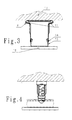
- Fig. 3 shows a spacer bracket according to the invention, mounted on the ceiling, in a front view. The vibrations introduced via the cladding elements (18) are passed through the bulges (8) in an absorbing or damped manner into the anchoring base (13).
- retaining teeth (17) are provided following the two laterally extending stiffening beads (10).
- the insulation is at least temporarily secured in its position until the substructure (15) and the cladding elements (18) are finally prevented from sliding down.
- the ends of the two legs (7) are essentially pointed, so that they can be pressed more easily through the fabric of the insulation material, since the tips (19) cut open the fabric.
Landscapes
- Engineering & Computer Science (AREA)
- Architecture (AREA)
- Civil Engineering (AREA)
- Structural Engineering (AREA)
- Physics & Mathematics (AREA)
- Electromagnetism (AREA)
- Joining Of Building Structures In Genera (AREA)
- Building Environments (AREA)
- Finishing Walls (AREA)
Applications Claiming Priority (2)
| Application Number | Priority Date | Filing Date | Title |
|---|---|---|---|
| AT3822000U | 2000-05-24 | ||
| AT0038200U AT4696U1 (de) | 2000-05-24 | 2000-05-24 | Abstandsbügel zur herstellung von unterkonstruktionen für decken- oder wandverkleidungen |
Publications (3)
| Publication Number | Publication Date |
|---|---|
| EP1158111A2 true EP1158111A2 (fr) | 2001-11-28 |
| EP1158111A3 EP1158111A3 (fr) | 2002-01-02 |
| EP1158111B1 EP1158111B1 (fr) | 2007-03-14 |
Family
ID=3489089
Family Applications (1)
| Application Number | Title | Priority Date | Filing Date |
|---|---|---|---|
| EP01890156A Expired - Lifetime EP1158111B1 (fr) | 2000-05-24 | 2001-05-23 | Etrier espaceur pour la fixation de revêtements de plafond ou de paroi |
Country Status (3)
| Country | Link |
|---|---|
| EP (1) | EP1158111B1 (fr) |
| AT (2) | AT4696U1 (fr) |
| DE (1) | DE50112180D1 (fr) |
Cited By (1)
| Publication number | Priority date | Publication date | Assignee | Title |
|---|---|---|---|---|
| DE102017125873A1 (de) * | 2017-11-06 | 2019-05-09 | Binder Beteiligungs AG | Schwingbügel zur schallentkoppelnden Montage von Verkleidungen auf einem Wandbauteil |
Citations (4)
| Publication number | Priority date | Publication date | Assignee | Title |
|---|---|---|---|---|
| DE8310266U1 (de) | 1983-04-08 | 1983-09-08 | Dahmer, Karlheinz, 6369 Niederdorfelden | Abstandsklammer |
| DE9200731U1 (de) | 1992-01-23 | 1992-03-12 | Vogl, Erich R., 8535 Emskirchen | Vorrichtung zur Herstellung von abgehängten Decken |
| DE4234648A1 (de) | 1992-01-23 | 1993-07-29 | Erich R Vogl | Vorrichtung zur herstellung von abgehaengten decken |
| DE29504310U1 (de) | 1995-03-14 | 1995-05-04 | August Vormann GmbH & Co, 58256 Ennepetal | Abstandhalter zur Anordnung von Zwischenwänden oder -decken |
Family Cites Families (3)
| Publication number | Priority date | Publication date | Assignee | Title |
|---|---|---|---|---|
| US3225394A (en) * | 1963-05-08 | 1965-12-28 | Kaiser Gypsum Company Inc | Ceiling suspension clip |
| GB1061376A (en) * | 1963-06-18 | 1967-03-08 | Matthew Forkin | Improvements in the construction of suspended ceilings |
| FR2711695B1 (fr) * | 1993-10-21 | 1995-12-22 | Knauf Cie Platres | Suspente pour profilé de grande portée, notamment pour la réalisation de faux-plafonds. |
-
2000
- 2000-05-24 AT AT0038200U patent/AT4696U1/de not_active IP Right Cessation
-
2001
- 2001-05-23 EP EP01890156A patent/EP1158111B1/fr not_active Expired - Lifetime
- 2001-05-23 DE DE50112180T patent/DE50112180D1/de not_active Expired - Lifetime
- 2001-05-23 AT AT01890156T patent/ATE356911T1/de active
Patent Citations (4)
| Publication number | Priority date | Publication date | Assignee | Title |
|---|---|---|---|---|
| DE8310266U1 (de) | 1983-04-08 | 1983-09-08 | Dahmer, Karlheinz, 6369 Niederdorfelden | Abstandsklammer |
| DE9200731U1 (de) | 1992-01-23 | 1992-03-12 | Vogl, Erich R., 8535 Emskirchen | Vorrichtung zur Herstellung von abgehängten Decken |
| DE4234648A1 (de) | 1992-01-23 | 1993-07-29 | Erich R Vogl | Vorrichtung zur herstellung von abgehaengten decken |
| DE29504310U1 (de) | 1995-03-14 | 1995-05-04 | August Vormann GmbH & Co, 58256 Ennepetal | Abstandhalter zur Anordnung von Zwischenwänden oder -decken |
Cited By (1)
| Publication number | Priority date | Publication date | Assignee | Title |
|---|---|---|---|---|
| DE102017125873A1 (de) * | 2017-11-06 | 2019-05-09 | Binder Beteiligungs AG | Schwingbügel zur schallentkoppelnden Montage von Verkleidungen auf einem Wandbauteil |
Also Published As
| Publication number | Publication date |
|---|---|
| DE50112180D1 (de) | 2007-04-26 |
| AT4696U1 (de) | 2001-10-25 |
| EP1158111B1 (fr) | 2007-03-14 |
| ATE356911T1 (de) | 2007-04-15 |
| EP1158111A3 (fr) | 2002-01-02 |
Similar Documents
| Publication | Publication Date | Title |
|---|---|---|
| EP2416042A2 (fr) | Dispositif de suspension réglable | |
| EP3574164B1 (fr) | Console destinée à la fixation d'éléments de façade | |
| DE102019116051A1 (de) | Regalsystem und Nutzfahrzeug mit einem Regalsystem | |
| DE3879497T2 (de) | Metallstuetze. | |
| DE2610998B2 (de) | Halterung zur Befestigung von Bekleidungsplatten vor einer Bauwerkswand | |
| EP0430224B1 (fr) | Dispositif de fixation | |
| EP2206450A1 (fr) | Rails destinés à suspendre des armoires | |
| WO2012075996A1 (fr) | Profilé en u pour le montage serré d'une vitre garde-corps | |
| EP0010694B1 (fr) | Revêtement pour murs ou plafonds | |
| EP1158111A2 (fr) | Etrier espaceur pour la fixation de revêtements de plafond ou de paroi | |
| DE102007021431A1 (de) | System und Verfahren zur Anbringung von Dämmmaterialien an Bauwerken | |
| EP2927390B1 (fr) | Dispositif de maintien de façades | |
| DE4421614C2 (de) | Fassadenverkleidung | |
| DE202016105087U1 (de) | Halteschiene für einen französischen Balkon sowie Haltevorrichtung und Anordnung dafür | |
| AT524400B1 (de) | Schallabsorbierende Lamelle | |
| DE202006012370U1 (de) | System zur Anbringung von Dämmmaterialien an Bauwerken | |
| EP0652338A1 (fr) | Faux plafond | |
| DE202008008405U1 (de) | Verbindungsbeschlag | |
| EP2002066B1 (fr) | Dispositif de fixation d'elements de construction | |
| DE102007006401B4 (de) | Reinraumwand | |
| EP2486825B1 (fr) | Agencement de fixation | |
| DE202020000211U1 (de) | Distanzstück und System zum dauerhaften Befestigen eines Bauteils an wenigstens einem Befestigungspunkt | |
| DE19754022A1 (de) | Befestigungswinkel | |
| EP1990477B1 (fr) | Panneau de construction léger doté d'une baguette de profilé | |
| DE102019116078A1 (de) | Regalsystem, Profilelement und Verfahren zum Herstellen eines Profilelements |
Legal Events
| Date | Code | Title | Description |
|---|---|---|---|
| PUAI | Public reference made under article 153(3) epc to a published international application that has entered the european phase |
Free format text: ORIGINAL CODE: 0009012 |
|
| PUAL | Search report despatched |
Free format text: ORIGINAL CODE: 0009013 |
|
| AK | Designated contracting states |
Kind code of ref document: A2 Designated state(s): AT BE CH CY DE DK ES FI FR GB GR IE IT LI LU MC NL PT SE TR |
|
| AX | Request for extension of the european patent |
Free format text: AL;LT PAYMENT 20010621;LV PAYMENT 20010621;MK;RO PAYMENT 20010621;SI PAYMENT 20010621 |
|
| AK | Designated contracting states |
Kind code of ref document: A3 Designated state(s): AT BE CH CY DE DK ES FI FR GB GR IE IT LI LU MC NL PT SE TR |
|
| AX | Request for extension of the european patent |
Free format text: AL;LT PAYMENT 20010621;LV PAYMENT 20010621;MK;RO PAYMENT 20010621;SI PAYMENT 20010621 |
|
| RIC1 | Information provided on ipc code assigned before grant |
Free format text: 7E 04B 9/20 A, 7E 04B 9/18 B |
|
| AKX | Designation fees paid |
Free format text: AT BE CH CY DE DK ES FI FR GB GR IE IT LI LU MC NL PT SE TR |
|
| AXX | Extension fees paid |
Free format text: LT PAYMENT 20010621;LV PAYMENT 20010621;RO PAYMENT 20010621;SI PAYMENT 20010621 |
|
| 17P | Request for examination filed |
Effective date: 20021002 |
|
| RAP1 | Party data changed (applicant data changed or rights of an application transferred) |
Owner name: FUCHS, DIETRICH ANTON |
|
| GRAP | Despatch of communication of intention to grant a patent |
Free format text: ORIGINAL CODE: EPIDOSNIGR1 |
|
| GRAS | Grant fee paid |
Free format text: ORIGINAL CODE: EPIDOSNIGR3 |
|
| GRAA | (expected) grant |
Free format text: ORIGINAL CODE: 0009210 |
|
| AK | Designated contracting states |
Kind code of ref document: B1 Designated state(s): AT BE CH CY DE DK ES FI FR GB GR IE IT LI LU MC NL PT SE TR |
|
| AX | Request for extension of the european patent |
Extension state: LT LV RO SI |
|
| PG25 | Lapsed in a contracting state [announced via postgrant information from national office to epo] |
Ref country code: FI Free format text: LAPSE BECAUSE OF FAILURE TO SUBMIT A TRANSLATION OF THE DESCRIPTION OR TO PAY THE FEE WITHIN THE PRESCRIBED TIME-LIMIT Effective date: 20070314 Ref country code: NL Free format text: LAPSE BECAUSE OF FAILURE TO SUBMIT A TRANSLATION OF THE DESCRIPTION OR TO PAY THE FEE WITHIN THE PRESCRIBED TIME-LIMIT Effective date: 20070314 |
|
| REG | Reference to a national code |
Ref country code: GB Ref legal event code: FG4D Free format text: NOT ENGLISH |
|
| REG | Reference to a national code |
Ref country code: CH Ref legal event code: EP |
|
| REF | Corresponds to: |
Ref document number: 50112180 Country of ref document: DE Date of ref document: 20070426 Kind code of ref document: P |
|
| REG | Reference to a national code |
Ref country code: IE Ref legal event code: FG4D Free format text: LANGUAGE OF EP DOCUMENT: GERMAN |
|
| PG25 | Lapsed in a contracting state [announced via postgrant information from national office to epo] |
Ref country code: SE Free format text: LAPSE BECAUSE OF FAILURE TO SUBMIT A TRANSLATION OF THE DESCRIPTION OR TO PAY THE FEE WITHIN THE PRESCRIBED TIME-LIMIT Effective date: 20070614 |
|
| PG25 | Lapsed in a contracting state [announced via postgrant information from national office to epo] |
Ref country code: ES Free format text: LAPSE BECAUSE OF FAILURE TO SUBMIT A TRANSLATION OF THE DESCRIPTION OR TO PAY THE FEE WITHIN THE PRESCRIBED TIME-LIMIT Effective date: 20070625 |
|
| PG25 | Lapsed in a contracting state [announced via postgrant information from national office to epo] |
Ref country code: PT Free format text: LAPSE BECAUSE OF FAILURE TO SUBMIT A TRANSLATION OF THE DESCRIPTION OR TO PAY THE FEE WITHIN THE PRESCRIBED TIME-LIMIT Effective date: 20070814 |
|
| LTIE | Lt: invalidation of european patent or patent extension |
Effective date: 20070314 |
|
| NLV1 | Nl: lapsed or annulled due to failure to fulfill the requirements of art. 29p and 29m of the patents act | ||
| GBV | Gb: ep patent (uk) treated as always having been void in accordance with gb section 77(7)/1977 [no translation filed] |
Effective date: 20070314 |
|
| EN | Fr: translation not filed | ||
| EN | Fr: translation not filed | ||
| PG25 | Lapsed in a contracting state [announced via postgrant information from national office to epo] |
Ref country code: GB Free format text: LAPSE BECAUSE OF FAILURE TO SUBMIT A TRANSLATION OF THE DESCRIPTION OR TO PAY THE FEE WITHIN THE PRESCRIBED TIME-LIMIT Effective date: 20070314 |
|
| REG | Reference to a national code |
Ref country code: IE Ref legal event code: FD4D |
|
| BERE | Be: lapsed |
Owner name: FUCHS, DIETRICH ANTON Effective date: 20070531 |
|
| PLBE | No opposition filed within time limit |
Free format text: ORIGINAL CODE: 0009261 |
|
| STAA | Information on the status of an ep patent application or granted ep patent |
Free format text: STATUS: NO OPPOSITION FILED WITHIN TIME LIMIT |
|
| PG25 | Lapsed in a contracting state [announced via postgrant information from national office to epo] |
Ref country code: IE Free format text: LAPSE BECAUSE OF FAILURE TO SUBMIT A TRANSLATION OF THE DESCRIPTION OR TO PAY THE FEE WITHIN THE PRESCRIBED TIME-LIMIT Effective date: 20070314 Ref country code: MC Free format text: LAPSE BECAUSE OF NON-PAYMENT OF DUE FEES Effective date: 20070531 Ref country code: DK Free format text: LAPSE BECAUSE OF FAILURE TO SUBMIT A TRANSLATION OF THE DESCRIPTION OR TO PAY THE FEE WITHIN THE PRESCRIBED TIME-LIMIT Effective date: 20070314 |
|
| 26N | No opposition filed |
Effective date: 20071217 |
|
| PG25 | Lapsed in a contracting state [announced via postgrant information from national office to epo] |
Ref country code: BE Free format text: LAPSE BECAUSE OF NON-PAYMENT OF DUE FEES Effective date: 20070531 |
|
| PG25 | Lapsed in a contracting state [announced via postgrant information from national office to epo] |
Ref country code: FR Free format text: LAPSE BECAUSE OF FAILURE TO SUBMIT A TRANSLATION OF THE DESCRIPTION OR TO PAY THE FEE WITHIN THE PRESCRIBED TIME-LIMIT Effective date: 20071102 Ref country code: GR Free format text: LAPSE BECAUSE OF FAILURE TO SUBMIT A TRANSLATION OF THE DESCRIPTION OR TO PAY THE FEE WITHIN THE PRESCRIBED TIME-LIMIT Effective date: 20070615 Ref country code: IT Free format text: LAPSE BECAUSE OF FAILURE TO SUBMIT A TRANSLATION OF THE DESCRIPTION OR TO PAY THE FEE WITHIN THE PRESCRIBED TIME-LIMIT Effective date: 20070314 |
|
| PG25 | Lapsed in a contracting state [announced via postgrant information from national office to epo] |
Ref country code: FR Free format text: LAPSE BECAUSE OF FAILURE TO SUBMIT A TRANSLATION OF THE DESCRIPTION OR TO PAY THE FEE WITHIN THE PRESCRIBED TIME-LIMIT Effective date: 20070314 |
|
| PG25 | Lapsed in a contracting state [announced via postgrant information from national office to epo] |
Ref country code: CY Free format text: LAPSE BECAUSE OF FAILURE TO SUBMIT A TRANSLATION OF THE DESCRIPTION OR TO PAY THE FEE WITHIN THE PRESCRIBED TIME-LIMIT Effective date: 20070314 |
|
| PG25 | Lapsed in a contracting state [announced via postgrant information from national office to epo] |
Ref country code: LU Free format text: LAPSE BECAUSE OF NON-PAYMENT OF DUE FEES Effective date: 20070523 |
|
| PG25 | Lapsed in a contracting state [announced via postgrant information from national office to epo] |
Ref country code: TR Free format text: LAPSE BECAUSE OF FAILURE TO SUBMIT A TRANSLATION OF THE DESCRIPTION OR TO PAY THE FEE WITHIN THE PRESCRIBED TIME-LIMIT Effective date: 20070314 |
|
| PGFP | Annual fee paid to national office [announced via postgrant information from national office to epo] |
Ref country code: AT Payment date: 20110519 Year of fee payment: 11 |
|
| PGFP | Annual fee paid to national office [announced via postgrant information from national office to epo] |
Ref country code: DE Payment date: 20110519 Year of fee payment: 11 |
|
| PGFP | Annual fee paid to national office [announced via postgrant information from national office to epo] |
Ref country code: CH Payment date: 20110825 Year of fee payment: 11 |
|
| REG | Reference to a national code |
Ref country code: CH Ref legal event code: PL |
|
| REG | Reference to a national code |
Ref country code: AT Ref legal event code: MM01 Ref document number: 356911 Country of ref document: AT Kind code of ref document: T Effective date: 20120523 |
|
| PG25 | Lapsed in a contracting state [announced via postgrant information from national office to epo] |
Ref country code: CH Free format text: LAPSE BECAUSE OF NON-PAYMENT OF DUE FEES Effective date: 20120531 Ref country code: AT Free format text: LAPSE BECAUSE OF NON-PAYMENT OF DUE FEES Effective date: 20120523 Ref country code: LI Free format text: LAPSE BECAUSE OF NON-PAYMENT OF DUE FEES Effective date: 20120531 |
|
| REG | Reference to a national code |
Ref country code: DE Ref legal event code: R119 Ref document number: 50112180 Country of ref document: DE Effective date: 20121201 |
|
| PG25 | Lapsed in a contracting state [announced via postgrant information from national office to epo] |
Ref country code: DE Free format text: LAPSE BECAUSE OF NON-PAYMENT OF DUE FEES Effective date: 20121201 |