EP1159094B1 - Rohrbiegeverfahren und vorrichtung zur herstellung eines rohrabsatzes für eine kupplung - Google Patents
Rohrbiegeverfahren und vorrichtung zur herstellung eines rohrabsatzes für eine kupplung Download PDFInfo
- Publication number
- EP1159094B1 EP1159094B1 EP00903729A EP00903729A EP1159094B1 EP 1159094 B1 EP1159094 B1 EP 1159094B1 EP 00903729 A EP00903729 A EP 00903729A EP 00903729 A EP00903729 A EP 00903729A EP 1159094 B1 EP1159094 B1 EP 1159094B1
- Authority
- EP
- European Patent Office
- Prior art keywords
- pipe
- lasts
- connector
- tool
- offset
- Prior art date
- Legal status (The legal status is an assumption and is not a legal conclusion. Google has not performed a legal analysis and makes no representation as to the accuracy of the status listed.)
- Expired - Lifetime
Links
- 238000005452 bending Methods 0.000 title claims abstract description 17
- 238000004519 manufacturing process Methods 0.000 title claims abstract description 11
- 238000000034 method Methods 0.000 title claims abstract description 5
- 238000009434 installation Methods 0.000 claims description 7
- 238000003825 pressing Methods 0.000 claims description 3
- 230000001105 regulatory effect Effects 0.000 claims 1
- 239000004411 aluminium Substances 0.000 description 2
- XAGFODPZIPBFFR-UHFFFAOYSA-N aluminium Chemical compound [Al] XAGFODPZIPBFFR-UHFFFAOYSA-N 0.000 description 2
- 229910052782 aluminium Inorganic materials 0.000 description 2
- 239000003921 oil Substances 0.000 description 2
- 229910000906 Bronze Inorganic materials 0.000 description 1
- 229910000831 Steel Inorganic materials 0.000 description 1
- 239000004809 Teflon Substances 0.000 description 1
- 229920006362 Teflon® Polymers 0.000 description 1
- 239000010974 bronze Substances 0.000 description 1
- KUNSUQLRTQLHQQ-UHFFFAOYSA-N copper tin Chemical compound [Cu].[Sn] KUNSUQLRTQLHQQ-UHFFFAOYSA-N 0.000 description 1
- 239000010720 hydraulic oil Substances 0.000 description 1
- 238000005461 lubrication Methods 0.000 description 1
- 238000005259 measurement Methods 0.000 description 1
- 230000001012 protector Effects 0.000 description 1
- 239000010959 steel Substances 0.000 description 1
- 238000010618 wire wrap Methods 0.000 description 1
Images


Classifications
-
- B—PERFORMING OPERATIONS; TRANSPORTING
- B21—MECHANICAL METAL-WORKING WITHOUT ESSENTIALLY REMOVING MATERIAL; PUNCHING METAL
- B21D—WORKING OR PROCESSING OF SHEET METAL OR METAL TUBES, RODS OR PROFILES WITHOUT ESSENTIALLY REMOVING MATERIAL; PUNCHING METAL
- B21D7/00—Bending rods, profiles, or tubes
- B21D7/06—Bending rods, profiles, or tubes in press brakes or between rams and anvils or abutments; Pliers with forming dies
-
- B—PERFORMING OPERATIONS; TRANSPORTING
- B21—MECHANICAL METAL-WORKING WITHOUT ESSENTIALLY REMOVING MATERIAL; PUNCHING METAL
- B21D—WORKING OR PROCESSING OF SHEET METAL OR METAL TUBES, RODS OR PROFILES WITHOUT ESSENTIALLY REMOVING MATERIAL; PUNCHING METAL
- B21D11/00—Bending not restricted to forms of material mentioned in only one of groups B21D5/00, B21D7/00, B21D9/00; Bending not provided for in groups B21D5/00 - B21D9/00; Twisting
- B21D11/18—Joggling
Definitions
- the invention relates to a method and pipe-bending device for manufacturing a pipe-offset for a connector at the end of a pipe, needed in the extension of the connector of a pipe of a pipe layer installed on a surface, for example on the wall, in which said pipe-offset for the connector, i.e. two consecutive bends, are manufactured close to the end of the pipe due to the need of room of the connector, in order to move the end of the pipe in parallel to a certain distance from the level of the pipe layer, and in which the bends are achieved by placing the pipe between two lasts, which are pressed against each other with the help of an operating device and in which lasts there are the forms equal to the pipe-offset of the connector, i.e. both bends.
- Different types of pipe lines are installed in the industry to be used in pneumatic, hydraulic and lubrication systems.
- the pipes are usually installed next to each other as a neat pipe layer when the targets are in the same direction. It becomes necessary especially in connection with the renewal of apparatus to make pipe extensions with the help of pipe connectors, which do not in any way fit inside the thick pipe layer but the pipe that is fitted with the connector need therefore be fitted with a pipe-offset for the connector, i.e. the pipe must be bent outwards from the level of the pipe layer. Two consecutive bends are needed, by which the end of the pipe is moved outwards in parallel from the level of the pipe layer. In case such joints are needed for pipes that are situated next to each other, they are usually made by overlapping three pipe extensions at a distance from each other in the longitudinal direction, whereby the fourth pipe connector can again be on the same line with the first one.
- Portable pipe-bending devices are known as such, but they are not suitable for manufacturing a pipe-offset for a connector, because the force needed is essentially greater than that of a pipe of corresponding measurements in the making of one bend.
- Patent document US 4,232,542 presents a portable pipe-bending apparatus, which uses symmetric lasts. Those are not suitable for manufacturing bendings for a pipe-offset for a connector.
- the object of this invention is to achieve a method for producing pipe-offsets for connectors that makes the installation work easier and a corresponding pipe-bending tool.
- the features of the method according to the invention are presented in the adjoining patent claim 1 and the features of the pipe-bending tool according to the invention are presented in patent claim 2.
- the lasts are installed to the auxiliary frame, which is able to turn at least in a limited manner, most profitably all the way around, whereby the handhold of the device can be essentially the same notwithstanding the direction of the pipe lines that are to be installed.
- An ergonomic work approach requires that the handhold cannot turn into a difficult direction.
- the steering apparatus of the operating device for example an electric switch
- the operating device is most profitably a hydraulic cylinder, by which the necessary force is achieved for the thick pipes, but even battery operated operating devices equipped with conveyor screws can come into question especially in case of smaller pipes.
- the pressurized hydraulic oil needed by the hydraulic cylinder is produced by a hydraulic apparatus, which is connected to a tool according to the invention by connection leads of the necessary length.
- hydraulic machines it is possible to use devices that are correspondingly pneumatic.
- the operations of the hydraulic and pneumatic apparatus are steered by the operating devices for example with the help of an electric cable connection.
- the fixed last is supported from the end of the guides of the moving last.
- Supporting bars situated underneath the lasts are profitably also used, whereby stiffness is achieved by the structure at the same time that the lasts are still open from the top.
- an auxiliary pipe that is installed on top of the lasts may be profitably used; which effectively stiffens the auxiliary frame and the end part that is connected to it.
- a piping is installed on wall W, forming a pipe layer 5, i.e. the separate pipes 6 are essentially on the same level.
- the separate pipes 6 are essentially on the same level.
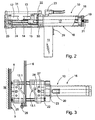
- the pipe-bending tool there is a frame 10 equipped with a handle 11 and a auxiliary frame 30 arranged to turn in relation to the frame.
- the auxiliary frame supports the pairs of lasts 12 and 13, figure 2.
- the operating device 16 i.e. the hydraulic cylinder
- the hydraulic cylinder has a drum part 17, a piston driver 18 with its pistons 19 and the end 22 of the cylinder, through which the piston driver comes out from the cylinder.
- the drum part 17 forms the axle of auxiliary frame 30 and is arranged in a rotating manner between the flange and auxiliary flange 23 of the hood 22.
- Auxiliary flange 23 is welded onto the cylinder drum.
- the handle 11 contains operating devices 29, here an electric switch, whereby the operations of the hydraulic apparatus (not shown) are steered.
- the hydraulic apparatus is attached with the help of pressurized oil hoses to the joints 20 and 21 of the tool.
- the electric switch is connected to the operating system of the hydraulic apparatus, whereby oil can be fed onto the chosen side of piston 19 with the help of the electric switch.
- Auxiliary frame 30 supports the end part 25 with the help of guide 14 and supporting bar 24. In the lighter models no support bar is needed at all, because guide 14 is sufficient to carry the end part.
- the auxiliary frame In the bending of thick pipes, the auxiliary frame is correspondingly equipped with an auxiliary support 31 fitted onto the lasts, which stiffens the auxiliary frame to an essential degree. However, the gap between lasts 12, 13 closes in the latter case from the top and the pipe must be pushed sideways to the gap.
- Figure 2 does not show the limiter 26, the operations of which are explained in connection with figure 3.
- the tool is placed against the pipe layer 5 at the place of installation in accordance with figure 3 and the pipe that is to be treated is set into the gap between lasts 12 and 13.
- the fixed last 12 includes here a limiter 26, against which pipe 6 is placed and with the help of which the pipe-offset for the connector is manufactured at a point specially chosen in relation to the end of the pipe.
- the last is first driven onto the pipe, after which its position is checked and the pressing takes place.
- lasts for each pipe size (the normal range being 6 - 18 mm) and the lasts can be quickly changed, because they are supported mainly with the help of pegs 27 both from the slide 15 and the end part 25. In addition to this, they are locked with Teflon coated screws 28, which can be screwed down and unscrewed by hand.
- Figure 4 shows a situation in which the vertical pipe 6 has already been shaped and the pipe-offset for the connector is ready.
- the auxiliary frame 30 is turned 90 degrees in relation to figures 2 and 3.
- the (operating device) apparatus is steered with the help of switch 29 to pull the moving last 13 backwards with the help of slide 15, whereby the gap opens and the pipe-offset for the connector that is ready can be taken out from the gap.
- Figure 5 presents the cross section of figure 4 from point V-V, but with the auxiliary frame 30 turned into about 45° angle.
- Piston driver 18 is attached with a wire-wrap to slide 15.
- limiter 26 can be installed on the chosen side of the tool, i.e. in the chosen last. The lasts can also be turned 180° in their own place (whereby there is no need to change the limiter).
- a protecting hood can be fitted as a finger protector underneath the slide.
- a pneumatic cylinder or battery operated screw turner can be used, especially in the case of smaller pipes, whereby outer power supply is not needed at all. Besides its great power, the advantage of a hydraulic cylinder is its good controllability.
Landscapes
- Engineering & Computer Science (AREA)
- Mechanical Engineering (AREA)
- Bending Of Plates, Rods, And Pipes (AREA)
- Shaping Of Tube Ends By Bending Or Straightening (AREA)
- Oscillators With Electromechanical Resonators (AREA)
- Measurement And Recording Of Electrical Phenomena And Electrical Characteristics Of The Living Body (AREA)
- Mechanical Coupling Of Light Guides (AREA)
Claims (10)
- Verfahren zur Herstellung einer zum Beispiel bei der Herstellung einer Rohrkupplung in einer auf einer Unterlage (W), zum Beispiel einer Wand, montierten Rohrlage (5) benötigten Kröpfung am Ende des Rohres (6), wobei wegen Platzbedarfs der Rohrkupplung (7) am Endabschnitt des Rohres (6) eine Kröpfung (8) gebildet wird, d.h. am Rohr zwei aufeinander folgende Biegungen (B1, B2) zur Parallelversetzung des Endes des Rohres (6) aus der Ebene der Rohrlage (5) heraus in einen Abstand von dieser angebracht werden, wobei die Biegungen (B1, B2) durch Einbringen des Rohres (6) zwischen zwei Biegeschablonen (12, 13), die mit einer Antriebsvorrichtung (16) gegeneinander gepresst werden, und die die Formen der Kröpfung (8), d.h. die den beiden Biegungen (B1, B2) entsprechenden Formen (12.1, 13.1) aufweisen, durchgeführt werden, dadurch gekennzeichnet, dass ein tragbares Handwerkzeug geschaffen wird, das die besagten Schablonen (12, 13) und die Antriebsvorrichtung (16) umfasst, und die Schablonen (12, 13) um die in Pressrichtung verlaufende Achse wenigstens begrenzt drehbar gestaltet werden, und dass das Rohr (6) so gestützt wird, dass sein Ende flexibel in einen Abstand von der Unterlage (W) gebogen werden kann, und dass das Werkzeug unmittelbar an der Stelle, an der die Rohrkupplung herzustellen ist, eingesetzt wird und dabei die Schablonen (12, 13) so in Richtung des Rohres (6) gedreht werden, dass dieses zwischen die Schablonen gebracht werden kann.
- Tragbares Handwerkzeug zur Herstellung einer Kröpfung (8) für eine Rohrkupplung an einem Rohr (6), zum Beispiel einem Rohr einer an einer Wand installierten Rohrlage, wobei wegen des Platzbedarfs der Rohrkupplung (7) in der Nähe des Rohrendes eine Kröpfung (8), d.h. zwei aufeinander folgende Biegungen (B1, B2) zur Parallelversetzung des Endes des Rohres (6) aus der Ebene der Rohrlage (5) heraus in einen Abstand von dieser hergestellt werden, wobei dieses Werkzeug einen Rahmen, eine Antriebsvorrichtung (16), Bedienungseinrichtungen (29) zur Steuerung der Energieversorgung der Antriebsvorrichtung (16), zwei den Formen (12.1, 13.1) der Kröpfung (8) entsprechende gegeneinander angeordnete Schablonen (12, 13), von denen die eine (13) zwecks Ausführung einer von der Antriebsvorrichtung (16) bewirkten linearen Bewegung beweglich und die andere (12) gegen diese lineare Bewegung fest angeordnet ist, umfasst, und wobei das zwischen die geöffneten Schablonen (12, 13) eingebrachte gerade Rohr (6) durch Gegeneinanderpressen dieser Schablonen mittels der Antriebsvorrichtung (16) in die durch die Schablonen bestimmte Form (12.1, 13.1) gebogen werden kann, dadurch gekennzeichnet, dass der Rahmen des Werkzeugs mit einem Griff (11) versehen ist und die Antriebsvorrichtung (16) für externe Energieversorgung oder für Betrieb mit eigenem Akku ausgelegt ist und wenigstens eine Führung (14) und auf dieser Führung einen Schlitten (15) zur Stützung der linearen Bewegung der Schablone (13) hat.
- Werkzeug nach Anspruch 2, dadurch gekennzeichnet, dass wenigstens eine der Schablonen (12, 13) einen Anschlag (26) zum Platzieren des Endes des quer gestellten Rohres (6) an die im voraus bestimmte Stelle hat.
- Werkzeug nach Anspruch 2 oder 3, dadurch gekennzeichnet, dass die Antriebsvorrichtung (16) den Werkzeugrahmen bildet und eine die Schablone (13) betätigende Schubstange (18) hat und das Werkzeug einen die Schablonen (12, 13) stützenden Hilfsrahmen (30) aufweist, der um eine durch die Schubstange (18) bestimmte Achse drehbar am Rahmen abgestützt ist.
- Werkzeug nach irgendeinem der Ansprüche 2 bis 4, dadurch gekennzeichnet, dass die Bedienungseinrichtungen (29) am Griff (11) angeordnet sind.
- Werkzeug nach irgendeinem der Ansprüche 2 bis 4, dadurch gekennzeichnet, dass die Bedienungseinrichtungen in einem Fußschalter angeordnet sind.
- Werkzeug nach irgendeinem der Ansprüche 2 bis 6, dadurch gekennzeichnet, dass die feste Schablone (12) zusätzlich zu den Führungen (14) durch wenigstens eine Stützstange (24) abgestützt ist, die in einem Abstand auf der zu den Schablonen (12, 13) entgegengesetzten Seite der Ebene der Führungen (14) angeordnet ist.
- Werkzeug nach irgendeinem der Ansprüche 2 bis 7, dadurch gekennzeichnet, dass unter den Führungen (14) und dem Schlitten (15) ein Schutzdeckel angeordnet ist.
- Werkzeug nach Anspruch 7, dadurch gekennzeichnet, dass auf den Schablonen (12, 13) lösbar eine die feste Schablone (12) stützende Hilfsstütze (31) zur Aussteifung der Konstruktion beim Biegen dicker Rohre angeordnet ist.
- Werkzeug nach irgendeinem der Ansprüche 2 bis 9, dadurch gekennzeichnet, dass die Schablonen (12, 13) durch Bolzen (28) befestigt sind und zu dem Werkzeug ein Schablonensatz gehört, der mehrere Schablonenpaare für Rohre verschiedener Dicke umfasst, wobei die Schablonen jedes Schablonenpaares abnehmbar befestigt werden können.
Applications Claiming Priority (3)
| Application Number | Priority Date | Filing Date | Title |
|---|---|---|---|
| FI990271 | 1999-02-11 | ||
| FI990271A FI990271A0 (fi) | 1999-02-11 | 1999-02-11 | Putkentaivutustyökalu |
| PCT/FI2000/000093 WO2000047345A1 (en) | 1999-02-11 | 2000-02-10 | Method and pipe-bending device for manufacturing a pipe-offset for a connector |
Publications (2)
| Publication Number | Publication Date |
|---|---|
| EP1159094A1 EP1159094A1 (de) | 2001-12-05 |
| EP1159094B1 true EP1159094B1 (de) | 2004-11-24 |
Family
ID=8553711
Family Applications (1)
| Application Number | Title | Priority Date | Filing Date |
|---|---|---|---|
| EP00903729A Expired - Lifetime EP1159094B1 (de) | 1999-02-11 | 2000-02-10 | Rohrbiegeverfahren und vorrichtung zur herstellung eines rohrabsatzes für eine kupplung |
Country Status (7)
| Country | Link |
|---|---|
| US (1) | US6575008B1 (de) |
| EP (1) | EP1159094B1 (de) |
| AT (1) | ATE283124T1 (de) |
| AU (1) | AU2551600A (de) |
| DE (1) | DE60016180T2 (de) |
| FI (1) | FI990271A0 (de) |
| WO (1) | WO2000047345A1 (de) |
Families Citing this family (4)
| Publication number | Priority date | Publication date | Assignee | Title |
|---|---|---|---|---|
| US20040258789A1 (en) * | 2003-06-19 | 2004-12-23 | Phillips James D. | Tube bending apparatus and method |
| FI20065538A7 (fi) * | 2006-08-31 | 2008-03-01 | Th Tarmatic Oy | Työkalu putken taivuttamiseksi |
| US10967415B2 (en) * | 2017-05-23 | 2021-04-06 | The Boeing Company | Electromagnetic field shaping system and method |
| BE1032890B1 (fr) * | 2024-08-05 | 2026-04-14 | Safran Aero Boosters Sa | Dispositif de cintrage d'une pièce allongée |
Family Cites Families (6)
| Publication number | Priority date | Publication date | Assignee | Title |
|---|---|---|---|---|
| FR889424A (fr) * | 1942-05-20 | 1944-01-10 | Weser Flugzeugbau Ges M B H | Matrice pour le cintrage de tuyaux dans des presses |
| US2771934A (en) * | 1951-06-28 | 1956-11-27 | Vapor Heating Corp | Apparatus for forming tubing into coils |
| US3507141A (en) * | 1968-02-14 | 1970-04-21 | William J Fisher | Apparatus for bending pipe |
| IT1156153B (it) * | 1978-04-06 | 1987-01-28 | Liri Costruzioni Mecc | Perfezionamento in un apparecchio curvatubi idraulico portatile a comando manuale provvisto di testa girevole ed elementi curvanti reversibili per invertire la direzione del la curvatura del tubo |
| US4942757A (en) * | 1989-03-31 | 1990-07-24 | Burndy Corporation | Hydraulic press with infinite head rotation |
| US5653139A (en) * | 1995-05-18 | 1997-08-05 | Pacific Benders, Inc. | Portable rebar bending device and method |
-
1999
- 1999-02-11 FI FI990271A patent/FI990271A0/fi unknown
-
2000
- 2000-02-10 EP EP00903729A patent/EP1159094B1/de not_active Expired - Lifetime
- 2000-02-10 AU AU25516/00A patent/AU2551600A/en not_active Abandoned
- 2000-02-10 US US09/890,719 patent/US6575008B1/en not_active Expired - Fee Related
- 2000-02-10 WO PCT/FI2000/000093 patent/WO2000047345A1/en not_active Ceased
- 2000-02-10 DE DE60016180T patent/DE60016180T2/de not_active Expired - Fee Related
- 2000-02-10 AT AT00903729T patent/ATE283124T1/de not_active IP Right Cessation
Also Published As
| Publication number | Publication date |
|---|---|
| EP1159094A1 (de) | 2001-12-05 |
| US6575008B1 (en) | 2003-06-10 |
| DE60016180T2 (de) | 2005-12-29 |
| WO2000047345A1 (en) | 2000-08-17 |
| ATE283124T1 (de) | 2004-12-15 |
| FI990271A0 (fi) | 1999-02-11 |
| DE60016180D1 (de) | 2004-12-30 |
| AU2551600A (en) | 2000-08-29 |
Similar Documents
| Publication | Publication Date | Title |
|---|---|---|
| DE102008007520B4 (de) | Oberflächenbearbeitungsgerät | |
| CA2238159A1 (en) | Modular multipurpose bending machine and its linear positioning system | |
| NO147739B (no) | Roerboeyemaskin. | |
| CA3082941C (en) | Attachment and handling device with an attachment | |
| US6575008B1 (en) | Method and pipe-bending device for manufacturing a pipe-offset for a connector | |
| CN108655305A (zh) | 一种具有导轮的加强型电缆线裁切机构 | |
| EP4678307A3 (de) | Vorrichtung und verfahren zum biegen von stäben | |
| US5632174A (en) | Metal bending machine | |
| EP1389149B1 (de) | Werkzeug für biegemaschine | |
| BR9104750A (pt) | Maquina de curvar tubos com rolos em tandem | |
| CN216461026U (zh) | 一种管材压弯装置 | |
| CN108705301B (zh) | 一种家用美式管钳组装设备 | |
| US3782162A (en) | Manipulator | |
| CN211191780U (zh) | 一种弯箍机物料抓取装置 | |
| CA1201049A (en) | Apparatus and method for press forming | |
| EP2085180A1 (de) | Oberflächenbearbeitungsgerät | |
| JP2918529B1 (ja) | 管材曲げ装置 | |
| US6266988B1 (en) | Cross rolling machine | |
| CN118558799A (zh) | 一种冷柜机箱钣金加工用全自动弯折成型设备 | |
| CN207508036U (zh) | 一种冷作滚圆机 | |
| CN2848402Y (zh) | 纵剪、收卷、矫平联合机组用矫平机 | |
| CA2067732A1 (en) | Process for the two-directional bending of sheet metal | |
| US3511074A (en) | Wire bender | |
| KR102748249B1 (ko) | 케이블 밴딩장치 | |
| CN220144425U (zh) | 中央空调安装用弯管机 |
Legal Events
| Date | Code | Title | Description |
|---|---|---|---|
| PUAI | Public reference made under article 153(3) epc to a published international application that has entered the european phase |
Free format text: ORIGINAL CODE: 0009012 |
|
| 17P | Request for examination filed |
Effective date: 20010828 |
|
| AK | Designated contracting states |
Kind code of ref document: A1 Designated state(s): AT BE CH CY DE DK ES FI FR GB GR IE IT LI LU MC NL PT SE |
|
| AX | Request for extension of the european patent |
Free format text: AL;LT;LV;MK;RO;SI |
|
| 17Q | First examination report despatched |
Effective date: 20030211 |
|
| GRAP | Despatch of communication of intention to grant a patent |
Free format text: ORIGINAL CODE: EPIDOSNIGR1 |
|
| GRAS | Grant fee paid |
Free format text: ORIGINAL CODE: EPIDOSNIGR3 |
|
| GRAA | (expected) grant |
Free format text: ORIGINAL CODE: 0009210 |
|
| AK | Designated contracting states |
Kind code of ref document: B1 Designated state(s): AT BE CH CY DE DK ES FI FR GB GR IE IT LI LU MC NL PT SE |
|
| PG25 | Lapsed in a contracting state [announced via postgrant information from national office to epo] |
Ref country code: LI Free format text: LAPSE BECAUSE OF FAILURE TO SUBMIT A TRANSLATION OF THE DESCRIPTION OR TO PAY THE FEE WITHIN THE PRESCRIBED TIME-LIMIT Effective date: 20041124 Ref country code: ES Free format text: LAPSE BECAUSE OF FAILURE TO SUBMIT A TRANSLATION OF THE DESCRIPTION OR TO PAY THE FEE WITHIN THE PRESCRIBED TIME-LIMIT Effective date: 20041124 Ref country code: CH Free format text: LAPSE BECAUSE OF FAILURE TO SUBMIT A TRANSLATION OF THE DESCRIPTION OR TO PAY THE FEE WITHIN THE PRESCRIBED TIME-LIMIT Effective date: 20041124 Ref country code: BE Free format text: LAPSE BECAUSE OF FAILURE TO SUBMIT A TRANSLATION OF THE DESCRIPTION OR TO PAY THE FEE WITHIN THE PRESCRIBED TIME-LIMIT Effective date: 20041124 Ref country code: AT Free format text: LAPSE BECAUSE OF FAILURE TO SUBMIT A TRANSLATION OF THE DESCRIPTION OR TO PAY THE FEE WITHIN THE PRESCRIBED TIME-LIMIT Effective date: 20041124 Ref country code: NL Free format text: LAPSE BECAUSE OF FAILURE TO SUBMIT A TRANSLATION OF THE DESCRIPTION OR TO PAY THE FEE WITHIN THE PRESCRIBED TIME-LIMIT Effective date: 20041124 |
|
| REG | Reference to a national code |
Ref country code: GB Ref legal event code: FG4D |
|
| REG | Reference to a national code |
Ref country code: CH Ref legal event code: EP |
|
| REF | Corresponds to: |
Ref document number: 60016180 Country of ref document: DE Date of ref document: 20041230 Kind code of ref document: P |
|
| REG | Reference to a national code |
Ref country code: IE Ref legal event code: FG4D |
|
| PG25 | Lapsed in a contracting state [announced via postgrant information from national office to epo] |
Ref country code: LU Free format text: LAPSE BECAUSE OF NON-PAYMENT OF DUE FEES Effective date: 20050210 Ref country code: IE Free format text: LAPSE BECAUSE OF NON-PAYMENT OF DUE FEES Effective date: 20050210 Ref country code: CY Free format text: LAPSE BECAUSE OF FAILURE TO SUBMIT A TRANSLATION OF THE DESCRIPTION OR TO PAY THE FEE WITHIN THE PRESCRIBED TIME-LIMIT Effective date: 20050210 |
|
| REG | Reference to a national code |
Ref country code: GB Ref legal event code: 732E |
|
| PG25 | Lapsed in a contracting state [announced via postgrant information from national office to epo] |
Ref country code: SE Free format text: LAPSE BECAUSE OF FAILURE TO SUBMIT A TRANSLATION OF THE DESCRIPTION OR TO PAY THE FEE WITHIN THE PRESCRIBED TIME-LIMIT Effective date: 20050224 Ref country code: GR Free format text: LAPSE BECAUSE OF FAILURE TO SUBMIT A TRANSLATION OF THE DESCRIPTION OR TO PAY THE FEE WITHIN THE PRESCRIBED TIME-LIMIT Effective date: 20050224 Ref country code: DK Free format text: LAPSE BECAUSE OF FAILURE TO SUBMIT A TRANSLATION OF THE DESCRIPTION OR TO PAY THE FEE WITHIN THE PRESCRIBED TIME-LIMIT Effective date: 20050224 |
|
| PG25 | Lapsed in a contracting state [announced via postgrant information from national office to epo] |
Ref country code: MC Free format text: LAPSE BECAUSE OF NON-PAYMENT OF DUE FEES Effective date: 20050228 |
|
| RAP2 | Party data changed (patent owner data changed or rights of a patent transferred) |
Owner name: TH TARMATIC OY |
|
| RIN2 | Information on inventor provided after grant (corrected) |
Inventor name: HUHTALA, TARMO |
|
| NLV1 | Nl: lapsed or annulled due to failure to fulfill the requirements of art. 29p and 29m of the patents act | ||
| REG | Reference to a national code |
Ref country code: CH Ref legal event code: PL |
|
| PLBE | No opposition filed within time limit |
Free format text: ORIGINAL CODE: 0009261 |
|
| STAA | Information on the status of an ep patent application or granted ep patent |
Free format text: STATUS: NO OPPOSITION FILED WITHIN TIME LIMIT |
|
| 26N | No opposition filed |
Effective date: 20050825 |
|
| REG | Reference to a national code |
Ref country code: IE Ref legal event code: MM4A |
|
| ET | Fr: translation filed | ||
| PG25 | Lapsed in a contracting state [announced via postgrant information from national office to epo] |
Ref country code: PT Free format text: LAPSE BECAUSE OF NON-PAYMENT OF DUE FEES Effective date: 20050424 |
|
| PGFP | Annual fee paid to national office [announced via postgrant information from national office to epo] |
Ref country code: FI Payment date: 20080206 Year of fee payment: 9 Ref country code: GB Payment date: 20080208 Year of fee payment: 9 Ref country code: IT Payment date: 20080228 Year of fee payment: 9 |
|
| PGFP | Annual fee paid to national office [announced via postgrant information from national office to epo] |
Ref country code: DE Payment date: 20080423 Year of fee payment: 9 Ref country code: FR Payment date: 20080225 Year of fee payment: 9 |
|
| GBPC | Gb: european patent ceased through non-payment of renewal fee |
Effective date: 20090210 |
|
| PG25 | Lapsed in a contracting state [announced via postgrant information from national office to epo] |
Ref country code: FI Free format text: LAPSE BECAUSE OF NON-PAYMENT OF DUE FEES Effective date: 20090210 |
|
| REG | Reference to a national code |
Ref country code: FR Ref legal event code: ST Effective date: 20091030 |
|
| PG25 | Lapsed in a contracting state [announced via postgrant information from national office to epo] |
Ref country code: DE Free format text: LAPSE BECAUSE OF NON-PAYMENT OF DUE FEES Effective date: 20090901 |
|
| PG25 | Lapsed in a contracting state [announced via postgrant information from national office to epo] |
Ref country code: GB Free format text: LAPSE BECAUSE OF NON-PAYMENT OF DUE FEES Effective date: 20090210 Ref country code: FR Free format text: LAPSE BECAUSE OF NON-PAYMENT OF DUE FEES Effective date: 20090302 |
|
| PG25 | Lapsed in a contracting state [announced via postgrant information from national office to epo] |
Ref country code: IT Free format text: LAPSE BECAUSE OF NON-PAYMENT OF DUE FEES Effective date: 20090210 |